
Volume 8, Number 2, July 2005
Implementation Of Certified Message Delivery For Tactical C3I Applications In A Battlefield Information System
- 1 Centre for Artificial Intelligence and Robotics (CAIR), Defence Research and Development Organisation (DRDO), Raj Bhawan Circle, Bangalore-01, India.
Abstract
Messaging is an accepted mechanism to implement data dissemination between tactical C3I applications. Certified Message Delivery (CMD) ensures in addition to the ensured delivery of a message by a robust messaging engine, the successful consumption of the message by the recipient application. It also ensures that the status acknowledgement is made available to the sender application for monitoring of data dissemination and re-propagation of messages that failed consumption. There are various ways in which Certified Message Delivery can be implemented. This paper discusses a robust and reliable implementation of CMD in tactical C3I applications in which messaging has been adopted as a mechanism for data dissemination. The implementation is asynchronous, with no blocking at the sender’s end. It is based on a network configuration in which there is an application server and database server in the local area network (LAN) of every formation/unit headquarters (HQ), and the LANs of the formation/unit HQs are connected to each other via a wide area network (WAN). Clients existing at every HQ, access the local application server, which in turn accesses the local database server, and there is a messaging server, which is a service that takes care of dissemination of data.
Introduction
A battlefield information system, like any information system, focuses on helping the user to translate data into meaningful information and thereby assists in making informed decisions in an acceptable time frame.
The functional subsystems, which generally constitute a modern battlefield information system, include operations, logistics, intelligence and terrain. Altogether, they assist the commander by providing him with useful information about the operational situation, available resources, activities of the enemy, and thus aid him in taking appropriate operational decisions in a near-real-time mode [1].
An important feature of this class of information system is dissemination of data. The flow of data in the entire corps zone which typically comprises of corps, division (div), brigade (bde), and battalion (bn) essentially needs a communication mechanism at the application layer of any network protocol. The communication mechanism is responsible for transfer of data or operationally important information from one headquarter (HQ) to another.
Messaging is an accepted mechanism to implement data transfer. Certified Message Delivery ensures, in addition to the delivery of a message by a robust messaging engine, the successful consumption of the message by the recipient application [2]. It also ensures that the status acknowledgement is made available to the sender application for monitoring of data transfer and re-propagation of messages that failed consumption [3].
This paper discusses Certified Message Delivery and its implementation in a battlefield information system.
Flow of messages in the battlefield
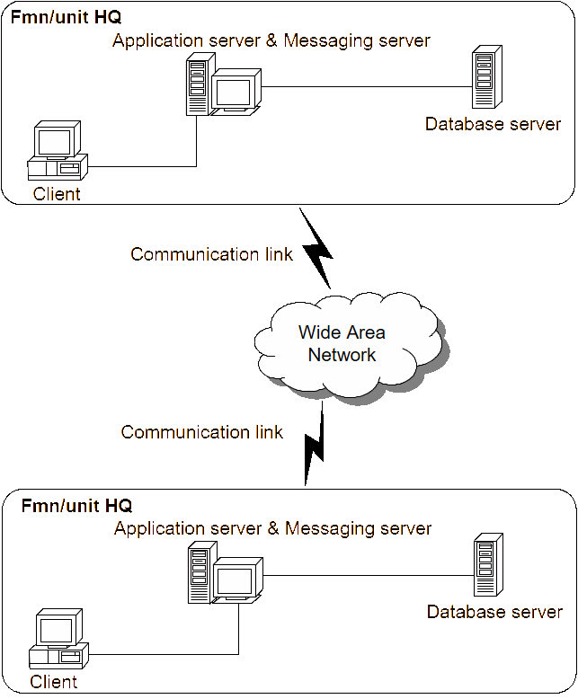
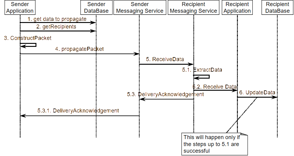
Figure 1 illustrates that the battlefield information systems in tactical formation (fmn)/unit headquarters are typically connected through electronic data channels via a battlefield intranet. Messaging is commonly the adopted communication mechanism and data is disseminated through the messaging service. Typically, the business artifacts that would be disseminated include master data, reports, orders, plans, returns, demands, approval requests, and responses. At any location, the user connected to the local node of the information system would disseminate one or more of these artifacts after following the business workflow involved in it. Once the user requests the system to disseminate data, the messaging server assumes responsibility of carrying the message and delivering to its intended recipient. The sequence of events in this process is as depicted in Figure 2.
The messaging engine has to necessarily be a robust one with sufficient mechanisms like priority queuing, temporary as well as persistent queues to handle exceptions due to temporary network unavailability, recipient unavailability, and so on. A detailed discussion of the messaging engine is beyond the scope of this paper.
Need for certified message delivery
As depicted in the sequence diagram in Figure 2, data propagation using a messaging service takes place in the following steps:
- Step 1: The sender application selects the data and the destination.
- Step 2: The sender application invokes the messaging service and hands over to the messaging service the data and the address to which the data needs to be propagated.
- Step 3: The messaging service operates between the fmn/unit HQs and hands over the data at the recipient end to the system application.
- Step 4: The recipient application receives the data, connects to the database server and performs the necessary database operations.
As a part of this process the following failures may occur:
- (1) At step 2 the application fails to hand over the data to the messaging service. (Possible causes: the messaging service is down, unexpected system exception, and so on.)
- (2) Even though step 2 is successful, at step 3, the messaging service fails to hand over the data to the recipient application. (Possible causes: any one of the WAN connectivity, the message server at the recipient end, or the recipient application server could be down leading to expiry of the specified Time-to-live (TTL) for the data packet).
- (3) Step 2 and 3 are successful but at step 4, the subsystem fails to update the database. (Possible causes: database server down, application server failure, LAN down, unchecked application exception, unexpected environment failures like power, and so on).
- (4) The order in which the messages are delivered to the recipient application may not be in the same order in which they were generated. This could lead to failures at the time of updating the database at the recipient end, if the two messages are dependent on each other and the order of consumption is critical.
In addition to these unexpected failures there would be cases of expected failures due to a planned down time for the recipient system, that is, in case of a fmn/unit moving from one location to the other. The planned down time may also result in any of the above-mentioned failures in data propagation.
For any of these failures, there needs to be a mechanism by which the originator of the data propagation (user) should be informed about the failure, and this information should be in terms of the domain language, that is, domain meta data (for example, Collation Structure modification dated March 12, 2004 has failed to disseminate to XXinfBn.) and there should a mechanism by which the user can resend the collation structure modifications at any instant of time.
The messaging service would provide failure status message only for the failure (2), (TTL time out). However, the failure message may not meet the requirement of the end user, as the failure message will not contain the domain meta data (because the domain meta data is known only to the application and not to the messaging service). The failures (1) and (3) and (4) will not be handled by the messaging service since handling these errors is beyond the scope of a messaging service. It is therefore mandatory that the application should take care of this important aspect by handling all types of errors occurring during data propagation and providing the user with appropriate delivery and consumption status. Further, user should have the facility to reinitiate the propagation of failed entities to appropriate destinations in case of a failure in delivery to the recipient or in consumption of the data by the recipient.
Implementation of Certified Message Delivery Mechanism takes care of the above-mentioned requirements and in effect enables the user to ensure guaranteed consumption of the message by the recipient.
Implementation of certified message delivery
The implementation of the Certified Message Delivery involves programming both the sender as well as the recipient. The process is an asynchronous one, that is, the sender does not wait for the recipient’s response to proceed with its other operations.
Programming the Sender Application:
The sender application is programmed to perform the following steps:
Initialization of data and propagation:
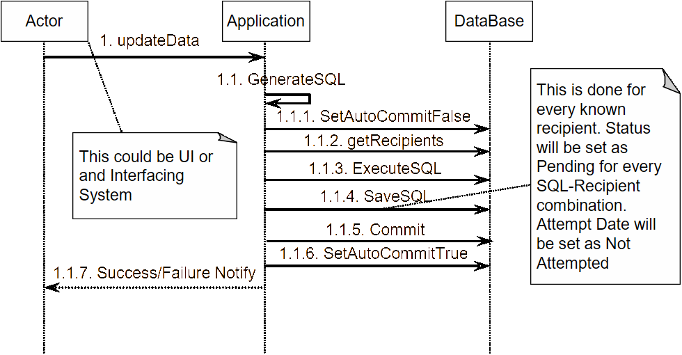
- Save the SQL statement in the database along with the recipient’s name. Set the Status as ‘Pending’ and Last Attempt Date as ‘Not Attempted’ as depicted in Figure 3. The following is the structure of the table:
- SQL table
- SQL Record No: System generated sequence values.
- SQL Statement: varchar2 (1000)
- Recipient: varchar2 (50)
- Status: varchar2 (20). Possible values are Pending, Pass, Fail
- Last Attempt Date: Date
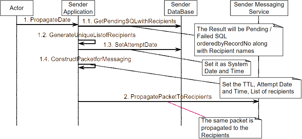
On initiation of propagation, construct the data packet for handing over to messaging service.
- Data Packet Structure
- Last Attempt Date: System date and time of this attempt
- Serializable object containing the list of objects, each containing a SQL statement along with its recipient.
- List of recipient addresses.
- Address of Sender (own address)
- Time to Live (TTL)
After constructing the packet, hand over the packet to the messaging service to propagate the packet. See Figure 4.
The recipient acknowledges the packet based on success or failure of consumption of the message. This is elaborated under the section ‘Programming the Recipient’. The actions that happen when the sender receives this acknowledgement are depicted in Figure 5.
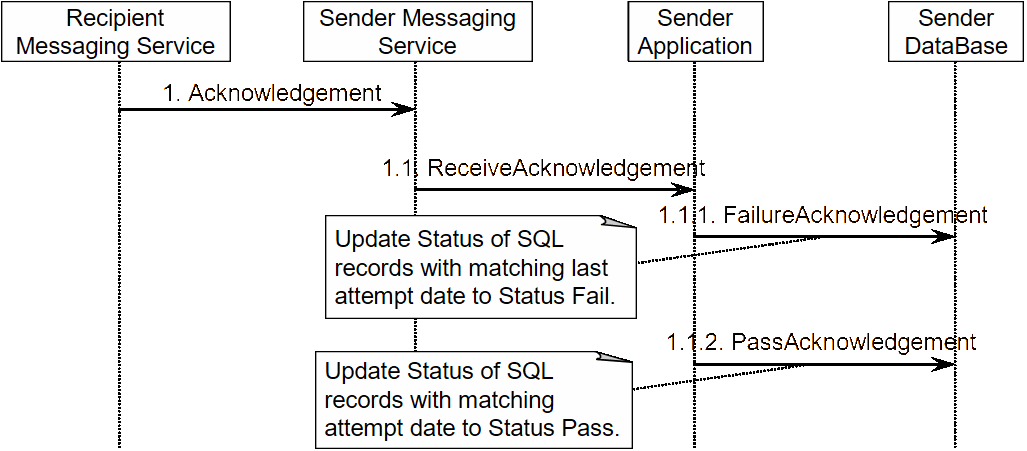
Receipt of Acknowledgement:
- Receive the acknowledgement.
- The Acknowledgement structure as constructed by the recipient Application
- Status: Possible values are Pass/ Fail
- Sender: Address of the recipient who has initiated the acknowledgement.
- Attempt Date: Same as the Last attempt date that was sent in the data packet.
- Set the status in the SQL table with the status received in the acknowledgement for the records where the Attempt Date matches with the Last Attempt Date and Sender matches with Recipient in the SQL table.
Programming the Recipient Application:
The recipient application is programmed to perform the following steps:
Receipt of Data Packet:
- Receive the Data Packet from the messaging service.
- Extract the SQL statements meant for self. Check that the SQL record number is greater than the last successfully executed SQL statement. If yes, then add the statement to a batch of SQL statements.
- Execute the batch.
- If successful send Pass acknowledgement.
- Else Rollback and send Fail acknowledgement to the Sender
Generation of Acknowledgement:
- Construct the acknowledgement in a structure as illustrated above and send it to the sender.
The sequence diagram in Figure 6 illustrates the above-listed steps in programming the recipient application.
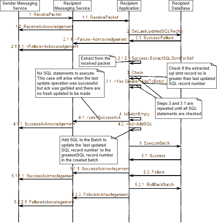
The state of the SQL records remains ‘Pending’ when the acknowledgement gets garbled up and does not reach the sender application. Their states get updated with the current status (Pass/Fail) when the sender subsequently initiates another propagation and the recipient application generates a new acknowledgement that successfully reaches the sender application.
Certified Message Delivery can achieve propagation of any data entity through minor modification in the implementation of the SQL table. Instead of maintaining SQL statements and SQL record numbers, (which is ideally suited in the case of master data propagation) the entity object along with the unique identifier for the entity should be maintained in the SQL table. For instance, dissemination reports can be handled by maintaining the report object and the unique report id in the SQL table.
System payoffs
Certified Messaging Delivery has a system-wide impact on battlefield information systems, given the critical importance of information dissemination in a near-real-time battlefield scenario. It ensures consumption of data by the recipient and more importantly it provides confidence to the solider on the battlefield that he would be able to know from the system whether the data he sent has been received by the recipient or not. In addition to that, the flexibility of sending the same data again to the recipient grants him better control over the real-time failures in the system.
Possible extensions
The sender application has to be programmed to facilitate the possibility of new fmn/unit HQ joining the system network after the system has been used over a long time and there is some master data that needs to be propagated to them. This can be achieved by extracting the SQL statements corresponding to the master data that have been saved in the SQL table for some fmn/unit and subsequently replicating them in the SQL table for the new fmn/unit.
Conclusion
Implementation of the Certified Message Delivery may be achieved in various other ways than that discussed here, but the crucial aspect is to ensure that any information system, which involves data propagation, has a robust and reliable Certified Message Delivery implementation, akin to the one discussed here.
Acknowledgements
The author is grateful to the Director, CAIR for the support and encouragement given.
References
[1] M. Ryan, “An Introduction to Battlefield Command Systems”, Australian Defence Force Journal, No. 124, pp. 7–15, May/Jun 1997.
[2] B. Schneier and J. Riordan, “A Certified E-mail Protocol”, 13th Annual Computer Security Applications Conference, ACM Press, December 1998 (accessed online at : http:// www.schneier.com/paper-certified-email.html).
[3] A. Tanenbaum, Computer Networks, Prentice Hall, September 2002.