
Volume 8, Number 2, July 2005
The MANPAD Threat To Commercial Aircraft
- 1 1 Head Electro-optics Group, DAPS, Cranfield University, Royal Military College of Science, Shrivenham, UK.
Abstract
Due to the current and ongoing international instability, the threat of future surface-to-air missile (SAM) attacks on commercial aircraft is real. Stop-gap measures to protect aircraft against man-portable air-defence (MANPAD) missile threats need to be evaluated until commercially viable systems are developed, tested and installed.
Introduction
Due to the current and ongoing international instability, the threat of future surface-to-air missile (SAM) attacks on commercial aircraft is real. Stop-gap measures to protect aircraft against man-portable air-defence (MANPAD) missile threats need to be evaluated until commercially viable systems are developed, tested and installed.
MANPADS
MANPADS are shoulder-fired SAMs designed to be the lowest level of air defence for ground units. Although current MANPADS have evolved into third-generation systems for modern militaries, first-generation systems are still of considerable threat to military and civilian air traffic. Legacy systems such as the SA-7b have been out of production for decades, but they can still easily be re-manufactured in a number of countries. The production numbers for all MANPADS is estimated to be around 500,000–700,000 [1] with many of these systems either produced by or provided to extremely unreliable groups. They are about 2 m in length, weigh about 15 to 18 kg and can easily be concealed in anything from a ski bag to a car or truck.
Generally MANPADS have a range of up to 8,000 m and a maximum altitude of around 4,000 m. Commercial aircraft fly much higher than this while on route and are therefore only exposed to the MANPAD threat during takeoff and landing. Under 6,500 m, a 16 km by 93 km area around an airport would have to be secured to ensure the approach and departure path was safe (25 nautical mile approach, 25 nautical mile departure path plus maximum MANPAD range at both ends).
Countermeasures
Although military countermeasure systems are quite mature, there have been extremely few examples of civilian aircraft being fitted with such systems. Estimated costs to install an IR countermeasure system on a commercial aircraft would be around US$1–3 million dollars per aircraft. The cost of equipping all the commercial US air traffic would therefore be from $6.6 billion to almost $20 billion. Installing a countermeasure system on a commercial aircraft would increase the drag of the airliner due to the addition of a pod or dome or require extensive airframe modifications. Although this drag might seem insignificant, it can, with the added weight of the system, increase the operating costs of an airline through added fuel costs [2].
CounterSim
Engagement scenarios for this paper were developed, modelled and simulated on CounterSim. Chemring Countermeasures of High Post, UK has developed this software for the study and evaluation of expendable countermeasures in the land, sea and air Electronic Warfare environments.
For this paper to remain at an unclassified level and hence to enable the greatest distribution of the results thus generated, classified SA-7b parameters were not sought for the CounterSim model but were instead found in open-source literature such as Jane’s [3]. A C-130 was used as the civilian heavy aircraft, as a model was readily available for CounterSim and the IR signature and structure of the C-130 is comparable to commercial airliners.
Aircraft on approach
Standard strategic approach
Generally, all large strategic aircraft follow similar descent profiles, with the difference being the initial approach airspeed, which is 250 Knots Indicated Airspeed (KIAS) for a Canadian C-130 and 300 KIAS for an A-310 [4].
Steep descent approach
The Steep Descent Approach increases the descent rate of the approach and reduces the level off time and altitude. For this approach an initial descent rate of 1,000 m/min is used with an initial descent velocity of 160 KIAS. The aircraft is levelled off at 325 m, slowed to 130 KIAS and flaps and gear selected. Once intercepted, the 3-degree glide slope is then flown to touchdown. This procedure would reduce the length of the approach distance to 20 km compared to 45 km for the standard approach. The approach parameters meet heavy aircraft specifications, have a standard 3-degree final approach and are a simple, low-tech method of reducing the threat by MANPADS at hostile airports.
Spiral approach procedure
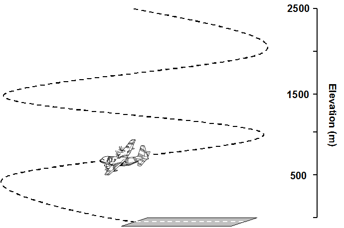
The theory behind the manoeuvre is that the slow-moving and turning aircraft will be more difficult to both target and hit. The aircraft approaches the airport at an SA-7b safe altitude of 2,500 m Above Ground Level and offset from the runway by 1,500 m. The aircraft is slowed to 170 KIAS and put in the half-flap configuration.
Once abeam of the runway threshold, the pilot begins a 45º banked turn towards the runway and sets a descent rate of 1,000 m/min. The airspeed is maintained at 170 KIAS. As shown in Figure 1, the first high key is 2,500 m, the second 1,500 m and the final 500 m, which must be met to ensure the proper rate of descent for the turn to the final approach. Similarly the first low key is at 2,000 m, the second 1,000 m and the final at touch down. At the third and final high key, the pilot ensures he is at 500 m and then selects the landing configuration of full flaps and gear down. (It is clearly recognised that such an approach would have a significant impact on operations at a busy commercial airport and may be restricted to military or less busy commercial airports. However, in the context of an emergency or perceived raised terrorist threat level it may be deemed suitable at busy commercial airports).
Modelling process
CounterSim was set up to simulate a SA-7b firing at an unprotected aircraft to determine from which distance and direction the missile could hit the aircraft. The 800 m to 4,000 m range of the SA-7b was broken into five 800 m ranges—800 m, 1,600 m, 2,400 m, 3,200 m and 4,000 m. Simulated firings were done every 30° from 0–180°. This was then repeated from 500–2,000 m at 500 m increments and then finally at the weapon’s ceiling, 2,300 m. Figure 2 is a polar plot of the data points modelled in CounterSim.
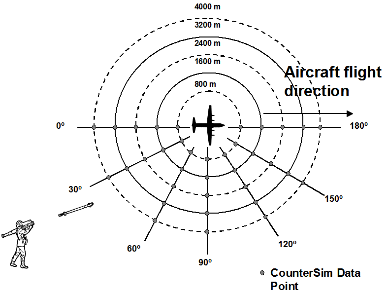
Based on these ranges, 35 data points were collected for each elevation, so for the five different elevations a total of 175 data points were collected. A data point is analogous to a MANPAD being fired at the target from that point on the polar plot. The maximum slant range [5] for the SA-7b is 4,200 m the maximum ceiling is 2,300 m, and maximum range 4,000 m. Calculations show that at the maximum range of 4,000 m, the SA-7 can only hit a target at approximately 1,280 m elevation. For this reason the 4,000 m data point was removed from the 2,300 m, 2,000 m and 1,500 m target elevations, reducing the threat circle for the SA-7b at long ranges.
Standard strategic approach results
Polar plots of the results, Figure 3, reveal that at low level the missile is strictly a tail-chase weapon with a very limited head on capability. Below 1,000 m, the ideal area to fire the missile is anywhere in a 30-degree angle from the tail of the aircraft. At 2,000–2,300 m altitude, the target can be engaged from abeam or slightly forward of abeam, but again the best results would favour at least a small tail-chase angle. (For the purposes of this modelling, a near miss is defined as the missile not impacting the aircraft directly, but passing sufficiently close such that if the missile had been fitted with a proximity fuze then there is a likelihood of some blast and/or fragment damage being sustained).
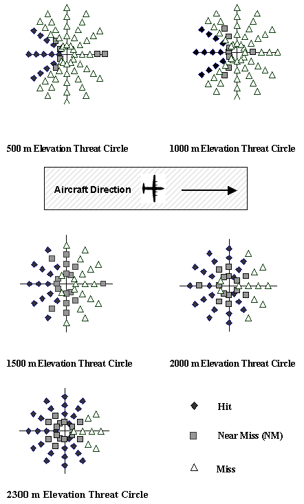
For potential SA-7b targets the best recommendations are to descend from 2,300 m to 1,000 m as quickly as possible. Although there is still a considerable tail threat at and below 1,000 m, it is significantly less than the approximately 300° threat envelope for the missile at 2,300 m. The best method for doing this would be to use one of the previously discussed approaches such as the Steep Descent Approach or the Spiral Approach. Also turning into the missile would be an effective manoeuvre to counter it—however, more simulations on this would have to be done to prove this point.
Tactical spiral approach results
The results in Figure 4 are for a left-hand turn Spiral Approach. The largest threat comes from the direction away from which the aircraft is turning. As the aircraft turns, the crossing rate of the aircraft to a viewer off the right wing is less than if the target were flying straight. This means that if the target is engaged from the side, the missile will have a greater chance of being successful since a slower crossing rate means the missile will need smaller control inputs to turn onto the target. The thermal signature of the target also changes as the hot rear exhaust areas are hidden behind the wing and engine nacelle as the aircraft turns head on. From the front the thermal signature is also much colder, especially in the 1.5–3 μm band in which the SA-7b operates. At the 800 m elevation threat ring the threat footprint will be 850 m from one side of the runway to 2,300 m on the other side. This area will most likely already be secure for airport operations to be undertaken, so the threat area in actual operations would be reduced.
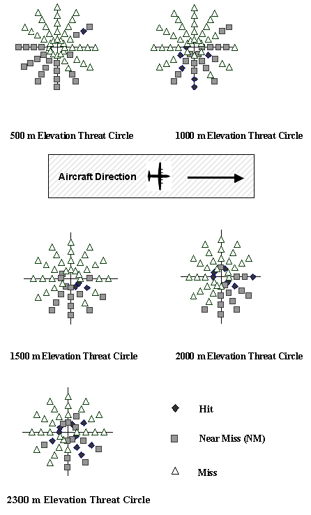
This approach is recommended for any non-countermeasure equipped landing since it offers the most protection to a landing aircraft. The hit percentage for an aircraft flying the Spiral Approach was reduced from 31% for the Standard Approach to less than 10%. Twenty percent of the data points were near misses, which means overall half the Standard Approach data points would result in a hit or near miss, while only a third had the same effect for the Spiral Approach. There are areas from which the aircraft is vulnerable but these are very specific to the direction of the spiral as the highest threat came from the direction opposite to the spiral bank angle. Since the spiral is flown offset to the airport, it is recommended that the first turn be away from high threat areas to ensure most of the approach is over lower threat zones.
Steep approach
The Steep Approach will have the same Threat Circles as the Standard Approach, but the distance over ground covered by the Standard Approach is much greater than for the Steep Approach. Since the Standard Approach also descends at half the rate of the Steep Approach, it will therefore take more time for the aircraft to come down. The length of the configuration stage is also longer, which means more flight time too. The larger flight path over the ground and time in the air gives the missile operator more choice of locations to fire from and additional preparation time.
Aircraft on departure
Departure profiles
Unlike approaches, departures are more standard and depend mostly on aircraft performance, weight and atmospheric conditions and are characterized by steep climb angles and maximum power settings. The standard C-130 departure of 180 KIAS and 500 m/min produces an over-ground flight path of approximately 25 km. Turning during a climb reduces the efficiency of the wing, which could result in a loss of airspeed and/or reduction in the rate of climb. Unless obstacle avoidance is required, turning in maximum rate-of-climb take offs is not recommended.
Departure results
As seen in Figure 5, at lower aircraft elevations the missile doesn’t have the time or distance required to turn onto the sightline needed to engage the target. As the aircraft ascends, there is more time and distance for the missile to react so it is able to both hit the target more times and become more accurate. As the altitude of the aircraft increase, the missile is able to increase its attack azimuth until 1,500 m when it is able to attack from abeam the aircraft and have some head-on capabilities. By an altitude of 2,000 m the threat circle has reduced to a 3,200 m radius because of the slant range limitations; however the missile is capable of hitting the target from almost any direction.
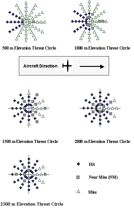
Unfortunately the departure parameters depend on so many variables that changing the standard departure is very difficult. However, at a rate of climb of 500 m/min the distance covered before being above the SA-7b ceiling is almost 25 km. Increasing the rate of climb to 750 m/min reduces this to 16.4 km and 1,000 m/min to only 12.2 km. Using max power, changing the wing configuration, reducing fuel or cargo weight, can increase climb rate.
Threat footprints
An important tool for mitigating the threat posed by MANPADS is the ability to map out threat zones for aircraft approaching and departing from a high-threat airport. The results of the CounterSim models were overlaid onto the over-ground decent profiles to produce a threat map or ‘footprint’ for the SA-7b. This footprint can be used as a template that can be placed over an airport in question to determine where successful MANPAD threats are most likely to originate. This footprint can then be used during the mission planning stage to reduce the MANPAD threat.
Standard approach and departure footprint
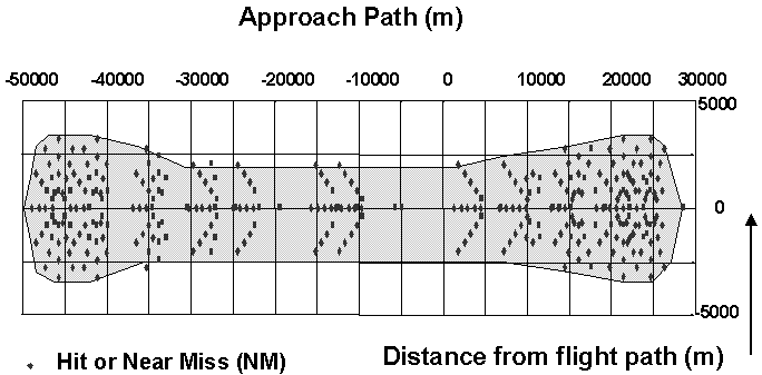
The combined standard approach and departure template shown in Figure 6 is almost 80 km by 6 km, or 480 km2. Obviously the premises for this paper is well founded in that large commercial aircraft are extremely vulnerable to easily available, low cost, and widely dispersed MANPADS.
Spiral descent approach and standard departure
The combination of the Spiral Descent and Standard Departure shown in Figure 7 offers the best protection to an aircraft without a countermeasure system.
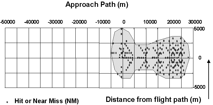
Although slightly widened, the overall threat footprint is reduced to about 32 km by 6 km or 192 km2. This represents a 60% reduction to the standard approach and descent footprint of 480 km2 and is much more manageable for a field commander. The landing threat footprint is very small and contains much of the area occupied by the airport, which most likely is already secured.
For non-countermeasure equipped heavy aircraft landing at a high SA-7b threat airport it is recommended that the Spiral Approach be used. This offers both the most difficult target to hit for the missile and a much reduced threat area to secure. To reduce the threat to aircraft during departure it is recommended that take-offs be restricted to night or poor weather conditions.
Conclusions
Departure is a much higher threat time for a commercial aircraft compared to approach. Aircraft without countermeasures sustained 87 hits and 57 near misses on approach and 127 hits and 36 near missed on departure. Threat Circles for the various elevations were overlaid onto the approach and departure paths of the aircraft to create threat footprints. It is recommended aircraft fly a Spiral Approach into a high threat area. There are not many options for departure so care must be taken in determining the time of the departure and aircraft performance parameters such as aircraft weight. To increase the climb rate of the aircraft, and thus shorten the length of the departure footprint, minimum fuel and cargo loads can help to reduce the MANPAD threat to civilian aircraft.
Further thoughts on MANPAD threat reduction
The current threat of a MANPADS attack on a civilian or unprotected military target is most likely to come from an unsophisticated enemy. They would not have any radar or other surveillance systems to aid in target detection. The missile user would have to detect and track the target during the pre-launch phase optically; therefore simple optical obscurants would reduce the likelihood of a target being detected. Airport operations should take advantage of poor weather conditions, such as fog or rain, to launch and recover aircraft. Simple camouflage techniques should also not be overlooked by civilian organizations or the Air Force. Disruptive paint and camouflage will make it difficult to see the aircraft, as would glint-free windscreens. Landing and anti-collision lights should also be used only when essential to limit the visual signature of the aircraft. Reducing aircraft engine noise would also make it more difficult for people on the ground to detect the aircraft.
References
[1] Thompson, Loren, "MANPADS: Scale & Nature of the Threat," Lexington Institute, 12 November 2003, available at www.lexingtoninstitute.org.
[2] Bolkcom, Elais et al, "Homeland Security: Protecting Airliners from Terrorist Missiles," Congressional Research Service, 3 November 2003. Available at www.fas.org.
[3] Janes Information Group, www.janes.com
[4] Telecomm Gerry Stark, Senior C-130 Simulator Instructor, Canadian Forces Base Trenton, 24 Jun 04.
[5] www.fas.org/man/dod-101/sys/missile/row/sa-7.htm.