
Volume 8, Number 2, July 2005
A Numerical Study On The Effect Of Explosive Reactive Armour On A Lightweight Armoured Vehicle’s Hull
- 1 Military Technical Academy, Bucharest, Bd. George Cosbuc, no. 81-83, Romania.
- 2 Cranfield University, Royal Military College of Science, Shrivenham, Swindon, SN6 8LA, United Kingdom.
Abstract
A numerical study using AUTODYN-2D was made in order to examine how to reduce the effect of a rear flyer plate from an explosive reactive armour (ERA) impacting a lightweight armoured vehicle hull at normal incidence. Various designs of protection systems were simulated. The dependence on deformation of the vehicle hull on the design of protection system is reported.
Introduction
One of the most weight-efficient methods of enhancing a vehicle’s protection against shaped charge jets is explosive reactive armour (ERA). The jet disruption is realised, mainly, by the application of a force perpendicular to the jet when the plates of ERA sandwich are flying apart. However, the use of this type of armour on Lightweight Armoured Vehicles (LAV) is limited by two problems [1].
Firstly, a single ERA sandwich alone is not able to defeat the total length of shaped charge jet because the front portion of a jet is not disturbed by the ERA action. This is a particular problem for LAVs as they tend to possess relatively thin hull walls that are easily perforated by a jet’s precursor.
Secondly, the rear plate of ERA is accelerated towards the hull by the explosive detonation products. If the vehicle’s hull is not sufficiently rigid then bending will ensue. If the hull wall is relatively thin, then deformation leading to cracking and spallation is possible. It is this issue that is addressed in this paper by evaluating potential approaches to reducing the damage.
Because of the issues raised in the previous paragraph there are relatively few examples of ERA armour integrated on LAV. One example is the Light Vehicle Armour System (L-VAS) on the Israeli M113. Each module of L-VAS consists of layers of steel, rubber and ceramics, including ERA and provides protection against various threats such as the Russian RPG-7V anti-tank rocket fitted with a single high-explosive anti-tank warhead, 14.5-mm and 20-mm armour-piercing rounds, and 155-mm artillery fragments [2]. This system is probably better described as a Passive Reactive Cassette (PRC) configuration which is more effective then an ERA cassette for the same weight because of additional material that is placed behind the initial ERA sandwich. The extra material provides it with the ability to reduce the length of the precursor [3]. Therefore the PRC concept partially solves the first problem. The weight of the L-VAS protection suite is 2 tonnes, a figure that allows the APC to maintain its manoeuvrability and speed characteristics [2].
ERA rear plate geometry and velocity
The acceleration of the plates is due by expansion of the gaseous products. To establish the plate velocity and geometry a two-dimensional non-linear finite difference hydrocode AUTODYN was used. A Euler solver was used to simulate the expansion of the detonation products; a Lagrangian solver was used to model the plate acceleration and deformation.
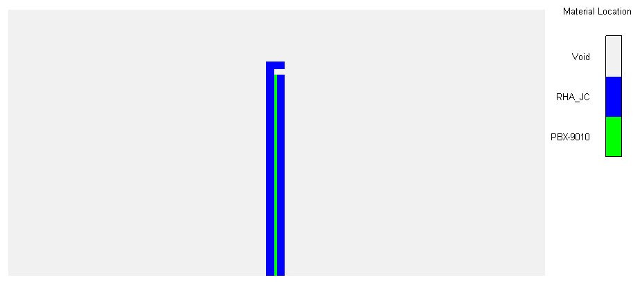
The initial ERA model geometry is shown in Figure 1. The Euler processor was used to model the explosive (PBX 9010) and the Lagrangian processor to model the ERA sandwich plates. All simulations were completed in axially symmetrical two-dimensional space. A central point of detonation was selected along the axis of symmetry. The thickness of flyer plates was 3 mm; the explosive interlayer was 1 mm thick. The axi-symmetrical half-length of the plates was 75 mm.
Hull wall geometry
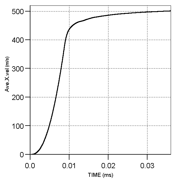
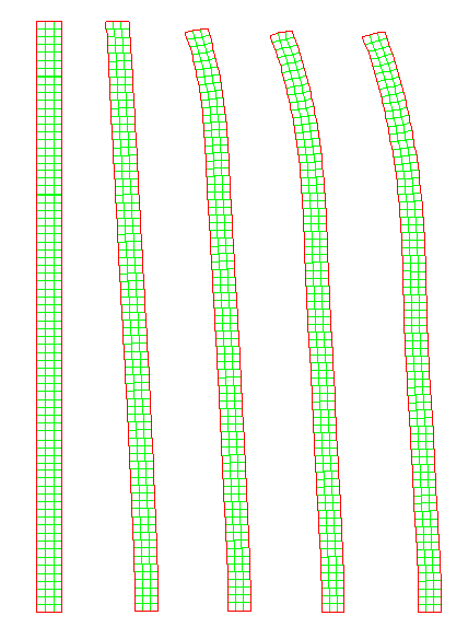
The vehicle hull was modelled using a Lagrangian solver. The wall thickness was set at 10 mm. The axi-symmetrical half-length of the wall was 200 mm. Boundary conditions were used to simulate 10-mm fixings at the plate’s extremities. The top plate surface was restrained from moving radially and a longitudinal restraint condition was applied to a rear section of 10 mm of plate (measured from the top of the hull). The hull wall and the protective system were introduced to the model at 3.6Δ10-2 ms when velocity of rear plate was 501 m/s and respective kinetic energy was 52.75 kJ. The rear plate average longitudinal (X) velocity evolution is presented in Figure 2. By that time the flyer plate has traversed 14.2 mm. The shape evolution is presented in Figure 3.
Protective system geometry
Various protective systems placed between the flyer plate and vehicle’s hull were simulated to evaluate their performance in reducing the effect of the flyer plate’s impact. Initially, a single plate of steel was placed between the hull and the rear flyer plate as an initial concept for a protective system. The thickness of the steel plate was varied as follows: 2, 4, 6, and 9 mm and the effect of the flyer plate on each thickness and the hull was evaluated. The spacing between the rear face of the protective system and the vehicle hull was 5 mm. Variants in which the protective system were presented as
circular bars, as a number of plates, or as a combination of plates and bars were also modelled. These special configurations (designated S1–S8) are shown in Figure 4 and are as follows:
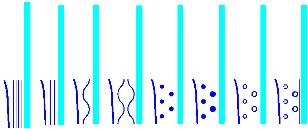
- S1—four 1-mm thickness plates at 3-mm equal separation; the last plate being 3 mm in front of the hull (Figure 4a);
- S2—two 2-mm thickness plates at 5-mm equal separation; the last plate being 5 mm in front of the hull (Figure 4b);
- S3—one 1.8 -mm curved plate with a 17.67-mm radius of curvature (Figure 4c);
- S4—two 1.8-mm curved plates with 17.67-mm radius of curvature (Figure 4d);
- S5—two layers of circular bars, first layer of three bars with 7-mm diameter and second of two bars with 8-mm diameter (Figure 4e);
- S6—two layers of circular bars, first layer of three bars with 8-mm diameter and second of two bars with 10-mm diameter (Figure 4f);
- S7—two layers of hollow circular bars, first layer of three bars of 8-mm diameter and the second of two bars of 10-mm diameter. The thickness of bar walls was 2 mm (Figure 4g); and
- S8—two layers of hollow circular bars and a 1.5-mm plate. First layer made with three bars of 8-mm diameter and the second by two bars of 10-mm diameter. The thickness of the bar walls was 2 mm (Figure 4h).
The areal densities of each protective system are shown in Table 1.
Materials properties
The materials used in the simulations were Rolled Homogeneous Armour (RHA) for ERA plates and protective system and High Hard Steel (HHS) for the hull. To calculate the pressures on impact in terms of the density and internal energy a Mie-Gruneissen equation of state was used based on a linear Shock – particle velocity formulation. Data for these was provided by the AUTODYN material libraries [4]. To calculate the deviatoric response of the RHA and HHS a Johnson-Cook constitute model was used [5]. The RHA parameters were taken from Lee et al [6] and the HHS parameters were taken from Johnson and Holmquist [7]. The failure model of HHS was based on a maximum tensile principal strain of 0.12 [8]; for the RHA a maximum tensile principal strain value of 0.5 was used. Table 2 lists the parameters used in the simulation.
S1 S2 S3 S4
a)b)c)d)
S5 S6 S7 S8
e)f)g)h)
| S1 | S2 | S3 | S4 | S5 | S6 | S7 | S8 | |
|---|---|---|---|---|---|---|---|---|
| kg/m2 | 31.2 | 31.2 | 15.6 | 31.2 | 22.4 | 32 | 20.5 | 32.2 |
| A (MPa) | B (MPa) | n | C | m | Tm (K) | |
|---|---|---|---|---|---|---|
| RHA | 1160 | 415.9 | 0.28 | 0.012 | 1.0 | 1809 |
| HHS | 1504 | 569.0 | 0.22 | 0.003 | 0.9 | 1783 |
A is the yield strength of the material, B is the work hardening constant, n is the work hardening exponent, C is the strain-rate sensitivity constant, m is the thermal softening exponent and Tm is the melting temperature.
Results
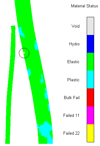
The study on rear flyer plate hull impact without any material situated between revealed large transient contact pressures of 3.5 GPa. In this case, the hull failed due to bending (Figure 5). For all others cases studied this event did not happen.
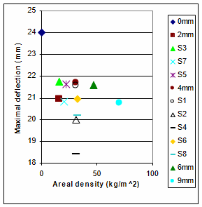
In order to assess the effect of adding a protective system between the flyer plate and the hull the following variables were evaluated: maximum total energy transferred to the hull, plastic work in the hull at the moment of maximum deflection, maximum deflection of hull centre, residual deflection of hull centre. The results are shown in Figures 6–9; each protective system is listed in order of the areal density.
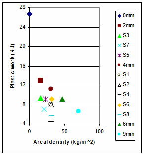
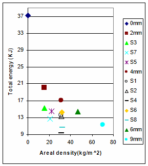
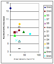
The total energy is the summation of the plastic work, the elastic strain energy the internal energy and the kinetic energy. The elastic strain energy stored in the hull during and after impact was transferred to the flyer plate during relaxation.
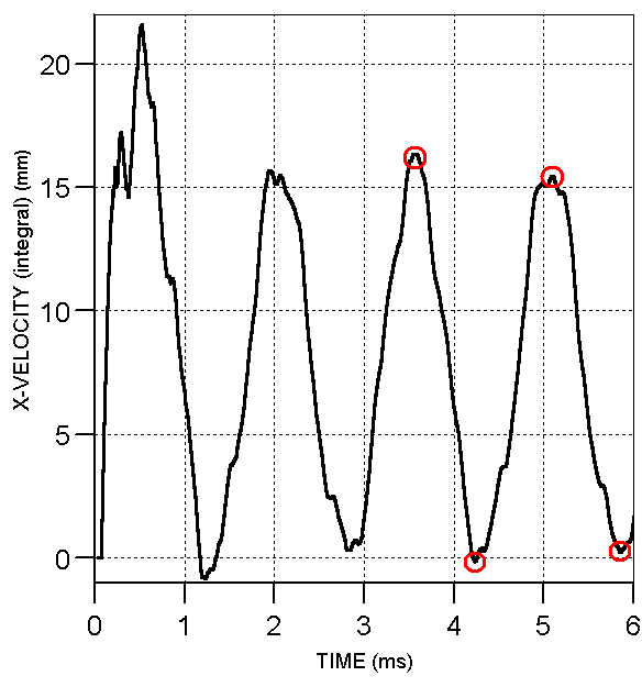
No static damping was applied to the simulations and therefore the hull would oscillate after the flyer plate was released. Therefore, to calculate the maximum deflection an average value of displacement was taken from four consecutive peaks during oscillation, two maximum values and two minimum values of deflection (see Figure 10).
Discussion of results and conclusions
This study has shown that the introduction of a protective system between the rear ERA flyer plate and the hull decreases the deformation of the hull wall.
In the case of the flat plates it was observed that a 2-mm plate is optimum and increasing the thickness of the protective system in this numerical study showed no improvement and in fact increased the amount of deformation (Figure 8). The reason for this is that thicker flat plates possess a higher flexural rigidity and therefore they are less susceptible to bending and hence less kinetic energy from the flyer plate was used to achieve plastic work (per unit mass). Instead, momentum is transferred to the thicker plates, which are themselves accelerated toward the hull. However, it should be noted that no boundary restraint was applied to the protective system plates and therefore at this stage we are uncertain as to whether sufficient restraint to these plates (that was not susceptible to shear failure) would negate this result.
In order to find a way to increase the level of kinetic energy consumed by plastic deformation additional protective system designs were simulated. The modifications were as follows (S1-S8):
- using more then one plate, instead of a single thick plate, but with the same total thickness;
- replacement of flat plates with curved plates for the same weight;
- replacement of plates with bars;
All three changes improved the process of flyer plate kinetic energy transfer to plastic work.
For S1 and S2 the results indicate that using a larger number of thinner plates is not always the best way to improve the performance. One of the reasons is that the first of the plates receive the largest part of the kinetic energy consumed by plastic deformation. This can be shown by comparing the total energy transferred to the hull for the “2-mm” case and S2 which consists of two 2-mm plates. The difference between the energy transferred is much larger when comparing the energy transferred to the hull without a protective system in place than with a single 2-mm plate in place. Adding another 2-mm plate (S2) reduces the energy transferred again by a considerably smaller amount. Furthermore, for the cases that were studied it is possible to obtain a result for a protective system with a relatively large number of thin plates that is similar with those obtained from a system with a smaller number of thicker plates (see for example, the results obtained for S1 and S2).
For S5 and S6 the results showed that using too large dimensions for the diameters bars can reduce the positive effect that the bars have. This does not happen when the hollow bars (S7 and S8) are used. Here, there is approximately the same mass as in the case S5 but a larger external diameter for each layer of bars.
The most important improvement was given by a combination between the first and second modification. Therefore, using two curved plates (S4) with a total mass equal with that of a 4-mm flat plate the protection offered to the hull is better then those obtained in the case of using a 9-mm flat plate. The reason for this is a greater value the of kinetic energy consumed by plastic deformation of the ERA rear plate when it comes into contact with the curved plate (case S4) because of the curved geometry of an appropriate thickness.
This numerical study has shown that the effect of an ERA flyer plate on a LAV’s hull can be reduced by careful consideration of the geometry of the protective system.
Acknowledgements
This numerical study was carried out during a postgraduate student’s visit to Cranfield University and was funded by the Military Technical Academy in Bucharest and Cranfield University at Shrivenham.
References
[2] www.israeli-weapons.com
[3] M. Brand, M. Mayseless, and R. Genussov, “Analytical Model to Analyse the Passive Reactive Cassette”, Proceding of 19th International Symposium. on Ballistics, Interlaken, Switzerland, 7–11 May, 2001.
[4] AUTODYNTM Theory Manual, Century Dynamics Limited, Dynamics House, Hurst Road, Horsham, Wet Sussex, RH12 2DT, UK.
[5] G. Johnson and W. Cook, “A Constitutive Model and Data for Metals Subjected to Large Strains, High Strain Rates And High Temperatures, Proceedings of 7th International Symposium on Ballistics, The Hague, The Netherlands, 19-21 April, 1983.
[6] W. Lee, H. Lee, H. Shin, “Ricochet of a Tungsten Heavy Alloy Long-rod Projectile from Deformable Steel Plates”, Journal of Physics D: Applied Physics, Vol. 35, pp. 2676–2686, 2002.
[7] G. Johnson and T. Holmquist, Test Data and Computational Strength and Fracture Model Constants for 23 Materials Subject to Large Strains, High Strain Rates and High Temperatures, Los Alamos National Laboratory, Los Alamos, New Mexico, LA-11463-MS, 1989.
[8] D. Yaziv, Y. Reifen, and G. Gans, “The Penetration Process of Long Rods at Interfaces Between Materials”, Proceedings of 21st International Symposium on Ballistics, Adelaide, Australia, 19–23 April, 2004.
[] P. Hazell, “Numerical Simulations of an Explosive Reactive Armour Rear Plate Impacting a Lightweight Armoured Vehicle’s Hull”, Journal of Battlefield Technology, Vol. 5, No. 3, pp. 1–4, November, 2002.