
Volume 5, Number 3, November 2002
Numerical Simulations of an Explosive Reactive Armour Rear Plate Impacting a Lightweight Armoured Vehicle's Hull
- 1 Cranfield University, The Royal Military College of Science, Shrivenham, Swindon, Wilts, SN6 8LA, United Kingdom.
Abstract
A numerical study using the explicit non-linear transient dynamic finite difference code AUTODYN-2D has been undertaken to examine the effect of a rear plate from an explosive reactive armour (ERA) impacting lightweight armoured vehicle hulls at normal incidence. Four thicknesses of ERA plate impacting high hardness steel armour and an aluminium alloy (7039) armour were simulated. The deformation of the vehicle hull and the measured strains are reported indicating critical areas around the fixings and the central region of impact.
Introduction
For many years now, explosive reactive armour (ERA) has been well proven in reducing the penetration of shaped-charge jets into MBT hulls. Indeed, this kind of appliqué protection is more suited to heavy vehicles than lightweight armoured vehicles for two reasons.
Firstly, a single ERA sandwich is not able to reduce totally the effect of a shaped-charge jet. The ERA sandwich is unable to disturb the front portion of a jet due to the time it takes for the explosive to detonate and accelerate the plates to a velocity that would cause sufficient disturbance. Typically a single ERA sandwich can reduce the penetration of a shaped-charge jet into a semi-infinite block of material by 90%. Without ERA, an RPG7 warhead would penetrate 300 mm into a semi-infinite Rolled Homogenous Armour (RHA) target. With ERA, the depth of penetration would be reduced to 30 mm, which means that a lightweight armoured vehicle hull is still likely be vulnerable to perforation by the jet. Nevertheless, with the use of suitable spall liners the vulnerability of the crew can be reduced substantially.
The second reason is that the sandwich plate closest to the vehicle hull is accelerated towards the hull by the explosive detonation products. This accelerating plate can cause substantial deformation and ultimately failure of a vehicle hull. It is this interaction between the ERA plate and the vehicle hull that is considered in this paper, which presents numerical analysis that examines the impact of a rear ERA flyer plate on a vehicle hull. The structural response of two lightweight armoured vehicle hulls is presented.
ERA back plate geometry and velocity
On detonation by a shaped-charge jet tip, the gaseous products that are formed by the explosion accelerate the plates of the ERA sandwich apart. To establish the plate velocity and geometry a two-dimensional non-linear finite difference hydrocode AUTODYN™ was used. This software is explained in detail elsewhere [1]. However in brief, this code solves the conservations laws of mass, momentum and energy based on initial boundary conditions. The user is prompted for an equation of state that describes the pressure in terms of the internal energy and volume and a constitutive relationship that calculates the flow stress in terms of a number of material- and application-dependent parameters including strain, strain-rate and temperature. Failure models can be introduced to describe the failure.
Both Euler and Lagrangian processors were used. The Euler processor was used to model the expansion of the detonation products and a Lagrangian processor was used to simulate the plate acceleration and deformation.
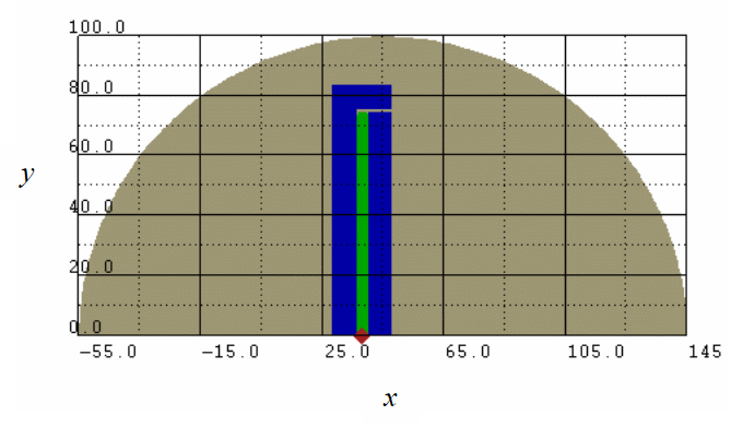
The initial model geometry is shown below in Figure 1. A Euler processor was used to model the explosive (PBX9010) and a Lagrangian processor was used to model the ERA sandwich plates and vehicle hull. A detonation point was chosen for the explosive that closely approximated the detonation point that would occur due to the central perforation of the sandwich by a shaped-charge jet. A “Flow-Out” boundary condition [1] was applied to the Euler subgrid to simulate the presence of a larger mesh and thereby reduced the run-time of the simulations. All simulations were completed in axially symmetrical two-dimensional space.
ExplosiveExplosiveDetonation pointDetonation pointERA back plateERA back plate
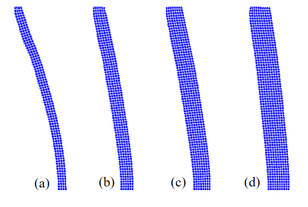
Four different ERA plate geometries were evaluated using this method maintaining a flyer plate to explosive thickness ratio of 2. The ERA plate thicknesses that were used to evaluate the effect on the vehicle hull were: 4, 6, 8 and 10 mm. The axi-symmetrical half-length of the plates was 75 mm. The average velocities respective kinetic energies of the flyer plates are presented below in Table 1. The residual shapes of the ERA rear plates are shown below in Figure 2. Each plate’s deformation is due to the detonation of the explosive. The thicker plates demonstrated more resistance to bending than the thinner plates due to their higher flexural rigidity.
| Thickness | 4 mm | 6 mm | 8 mm | 10 mm |
|---|---|---|---|---|
| Velocity (m/s) | 575 | 562 | 565 | 542 |
| KE (kJ) | 105.7 | 132.2 | 178.3 | 205.4 |
The similarity between the calculated velocities for each plate thickness is predicted by conducting an energy balance akin to Gurney [2].
ERA plate impact
The plates were allowed to accelerate to their terminal velocities at which point the vehicle hull plate was introduced into the simulations. All impacts occurred at normal incidence (that is, zero obliquity). Two different vehicle hulls were considered for numerical analysis: 28-mm thick Al 7039 and 10-mm thickness of High Hard (steel) Armour (HHA). Both thicknesses of material correspond to typical values used in modern lightweight armoured vehicles hull construction and correspond to an equal areal density of 77.5 kg/m2.
For all materials used in the analysis a linear Shock equation of state [1] and a Johnson Cook [3] constitutive model was used to simulate the material response to dynamic loading.
The linear shock-velocity relationship is given by:
(1)
where Us corresponds to the shock velocity, C0 corresponds to the bulk sound speed of the material, S is a constant and Up is the particle velocity. Using the conservation of mass momentum and energy it is possible to define the pressure-volume relationship and hence establish a Mie-Gruneisen form of the equation of state [1]. All equation-of-state parameters were taken from the AUTODYN material libraries [4].
To model the effects of the strain, strain rate and thermal softening on the flow stress of the material, a Johnson Cook constitutive relationship was used as shown in the following equation:
(2)
where A is the yield strength of the material, B is the strain hardening constant, n, is the strain hardening exponent, C is a strain rate constant, m is the thermal softening exponent and Tm is the melting temperature. All these constants are determined experimentally and are shown in Table 2.
| A (MPa) | B (MPa) | n | C | m | Tm (K) | |
|---|---|---|---|---|---|---|
| 1006 Steel | 350 | 275 | 0.36 | 0.022 | 1.000 | 1811 |
| Al 7039 | 220 | 500 | 0.22 | 0.016 | 0.905 | 933 |
| HHA | 1504 | 569 | 0.22 | 0.003 | 0.900 | 1783 |
The data for the Johnson Cook Model for the 1006 steel was taken from the AUTODYN Material library, the data for the Al 7039 was taken from [5] and the data for the HHA (High Hard Armour) was taken from [6].
When the ERA plate had reached its terminal velocity, the plate geometry and velocity was used to model the impact of the aluminium alloy and high hardness armour. The axi-symmetrical half-length of the hull plates was 200 mm; boundary conditions were used to simulate 10-mm fixings at the plate’s extremities. The top plate surface (y = 200 mm) was restrained from moving in the y direction and a section of plate 10-mm long measured from the top and applied to the rear of the plate was restrained from moving in the x direction (Figure 8). The spacing between the ERA and the vehicle hull was nominally 150 mm.

Results
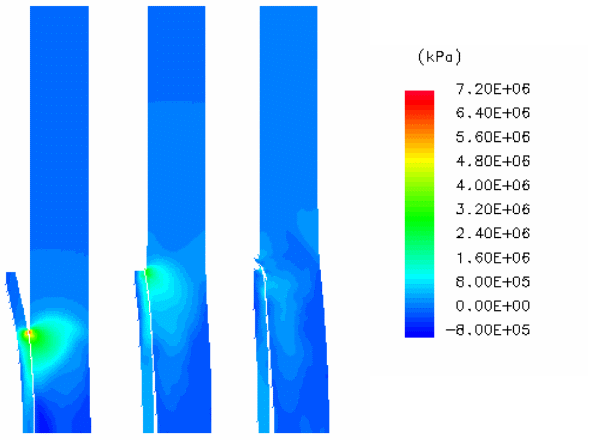
Due to the convex shape of the ERA plate that was formed, the impact of the vehicle hull starts with the central portion of the ERA plate interacting with the hull. The hull plate is accelerated and the ERA back plate is flattened against the vehicle plate. Large transient contact pressures are evident in the vehicle hull plate as the full ERA back plate comes into contact with the vehicle hull (see Figure 3).
Transient contact pressures of 4 GPa and 7 GPa were observed in the aluminium alloy and the high hardness steel plate respectively. Eventually the central section of the hull plate is accelerated away from the ERA back plate and the two become separated until plastic deformation reduces the rate of deformation. As the rate of deformation slows, interaction between the ERA back plate and the vehicle hull occurs again. This time, the contact pressures are reduced, the vehicle hull plate deformation ceases and the ERA back plate is repelled.
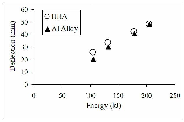
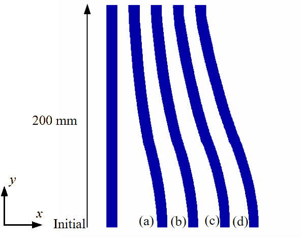
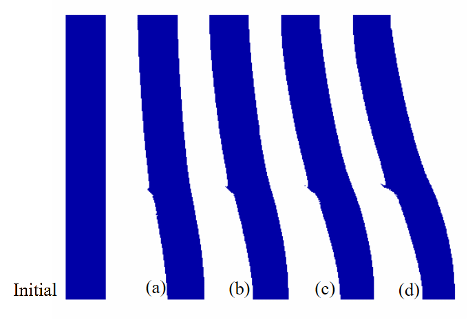
In each case it was noted that a large degree of deformation occurred. At higher impact energies, the deflection of the aluminium alloy and the steel plate are similar; however at lower velocities it was noted that the aluminium alloy deformed less (see Figure 4).
The residual deformation for both the HHA and aluminium alloy are shown in Figures 5 and 6. With the aluminium alloy, it can be seen that the ERA back plate penetrated into the vehicle hull as well as causing bending in the plate.
To assess the effect of the plate bending on the deformation at specific locations, gauge points were placed half way through the thickness of the hull plate (x = 5 mm for the HHA and x = 14 mm for the aluminium alloy), at the rear surface of the hull plate (x = 10 mm for the HHA and x = 28 mm for the aluminium alloy) and 0, 50, 100, 150 and 190 mm from the axis of symmetry (y = 0). Measurements of the maximum tensile strain in the second principle direction (parallel to the plate surface) were taken at these gauge points located at 0, 50, 100 and 190 mm from the central axis. The variation of maximum strain for each of the ERA plate thicknesses is presented in Figures 7, 9, 10 and 11.
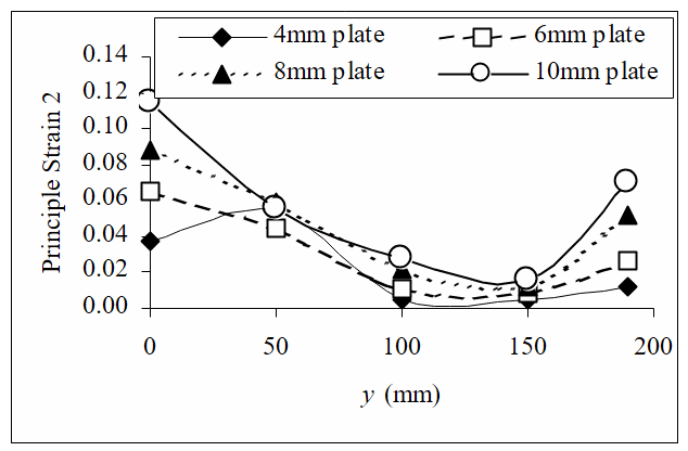
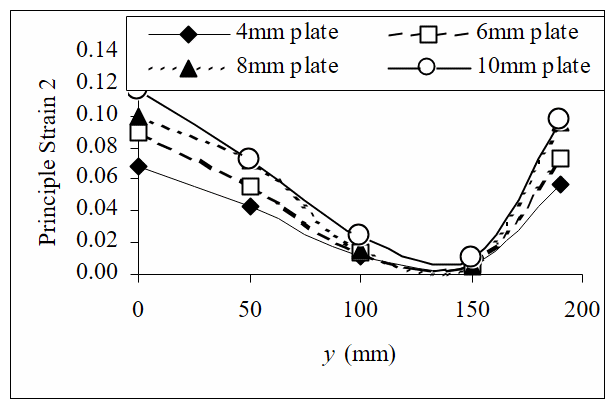
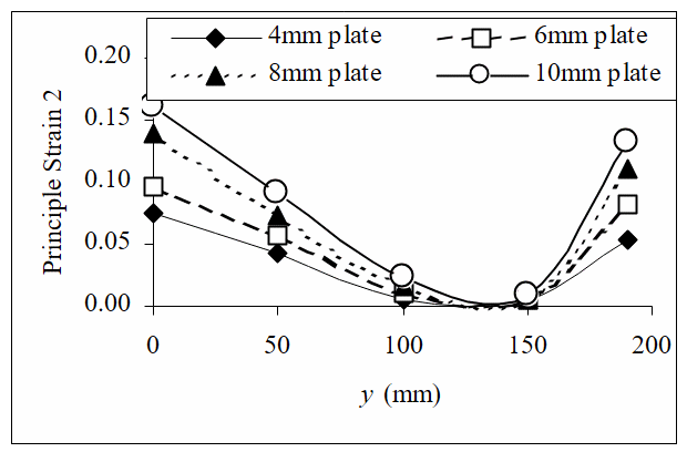
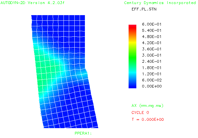
Generally, the larger the energy of the impact, the greater the deformation and therefore the larger the measured principal strains. HHA and aluminium alloy 7039 are both relatively brittle therefore we would expect that failure to occur in plates that are struck with ERA back plates of 6 mm and above. The quoted elongation to failure values for Al 7039 is 9% [5]; a typical value for the elongation to failure for a high-hardness steel (for example, ARMOX 500T) is also 9% [7]. Figures 7, 9, 10 and 11 show that there are two locations in the hull plates that are vulnerable to failure: at 0 mm and 190 mm from the central axis. The observed tensile strains at y = 190 mm are due to the bending stresses that are incurred by the plate during deflection. Since the location of the fixing prevents the plate from rotating at the edge, the hull plate is pulled away from its fixings as it deforms. If the fixings are perfectly rigid (as they are in these simulations) this results in large tensile strains parallel to the plate’s surface. Large strains were observed in the aluminium alloy at the outer edge (see Figure 11) and half way through the thickness of the HHA (see Figure 7). Measurements of effective plastic strain on the front surface of the hull plate close to the fixing location show very large values of plate deformation as shown in Figure 8. This failure is due to the bending of the plate; further simulations showed that this effect is reduced if larger sections of plate are used.
Large strains are also evident at y = 0 mm where the greatest deflection due to the impact has occurred. Large strains at y = 0 mm occurred at most notably with the aluminium alloy (Figure 11) with principal strains of 10% being observed during the impact of the 6-mm thick ERA back plate. These strains are as a result of the large degree of bending that is seen in the plate and would most probably be the source of tensile failure on the rear surface of the plate.
Concluding remarks
This study has shown the large deflections and the large strains that can occur when explosive reactive armour is detonated and propels its back plate into a vehicle hull. In this study, both the aluminium alloy (7039) and the HHA deformed similarly. Large strains (>10%) were measured when the vehicle hulls were struck by 8-mm and 10-mm ERA back plates with kinetic energies of 178.3 and 205.4 kJ respectively. For the HHA, the largest measured strains occurred at the location of the fixings; the aluminium alloy critical strains were located at the point of the maximum bulge. Increasing the size of the plate or allowing the edges of the plate to rotate would reduce the effective strain at the fixings. However, for the aluminium alloy it is likely that the large strains at the point of the maximum bulge would ultimately lead to tensile failure.
From the presented numerical data, it is clear that care must be used when applying ERA boxes to relatively lightweight hulls. Increasing the rigidity of the hull or introducing materials to reduce the impact of the ERA back plate can reduce the effects that have been observed in this numerical programme of research.
Acknowledgements
The author would like to acknowledge K. Kumthorncharoen who did some of the background research upon which this paper is based.
References
[1] AUTODYN™ Theory Manual, Century Dynamics Limited, Dynamics House, Hurst Road, Horsham, West Sussex, RH12 2DT, UK.
[2] M. Meyers, Dynamic Behaviour of Materials, John Wiley and Sons Inc., New York, 1994.
[3] G. Johnson and W. Cook, “A Constitutive Model and Data for Metals Subjected to Large Strains, High Strain Rates and High Temperatures”, Proceedings of the 7th International Symposium on Ballistics7, The Hague, The Netherlands, 1983, pp. 541-54.
[4] AUTODYN™ Material Libraries, Century Dynamics Limited, Dynamics House, Hurst Road, Horsham, West Sussex, RH12 2DT, UK.
[5] G. Gray, et al, Constitutive Equations for Annealed Metals Under Compression at High Strain Rates and High Temperatures, Los Alamos National Laboratory, Los Alamos, New Mexico, LA-12669-MS, 1994.
[6] G. Johnson and T. Holmquist, Test Data and Computational Strength and Fracture Model Constants for 23 Materials Subject to Large Strains, High Strain Rates and High Temperatures, Los Alamos National Laboratory, Los Alamos, New Mexico, LA-11463-MS, 1989.
[7] ARMOX™ 500T Data Sheet, SSAB, Oxelösund AB, 2002.