
Volume 5, Number 2, July 2002
Electro-Optical Systems Analysis: Part 1
- 1 Cranfield University, RMCS Shrivenham, Swindon, SN6 8LA, UK.
Abstract
This paper is the first in a series of short tutorial articles loosely based on tutorial sessions given at the Royal Military College of Science to Masters of Science (MSc) students who are studying on defence technology courses. The purpose of the tutorials is to enable students to do first-pass (rough) calculations on various aspects of electro-optical system. This type of analysis is typical of that which they may carry out in their potential future role as defence analysts. This first paper looks at calculating the power requirement of a laser and/or the sensitivity required of the detector for laser-beam riding, laser-warning receivers and laser-designation systems.
Introduction
The utilisation of laser technology on the modern battlefield is wide spread. It is necessary in some instances, for example in defence analysis, to make rough calculations on the feasibility of the operation of such systems in various conditions with little or practically no data available on the systems to be used. In some circumstances the data may simply be a report that a laser was used and a poor quality photograph of the alleged equipment. Under these circumstances it is therefore appropriate to undertake a process of very low-fidelity modelling to enable a decision of the probability of successful utilisation. This paper looks at such a low-fidelity model for laser-beam riding systems, laser-warning receivers and laser-designation/target-marking systems.
Laser beam properties
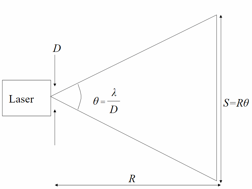
It is assumed that the laser beam can be considered to have a uniform (top hat) intensity function across the beam (this is clearly an approximation as a gaussian distribution is more likely). The laser system has an exit diameter of D a wavelength of λ and a power output of P watts, and with reference to Figure 1 the beam area (BA) at range R can be approximated as follows:
(1)
Laser-beam riding/laser-warning receivers
One technique for guiding a munition is called laser-beam riding. This usually involves the firing post having some form of sight, which is bore-sighted to a projected laser information field. The munition (an anti-tank guided weapon for example) then has a detector system ‘looking’ back at the firing post. The laser field therefore directly illuminates this detector. This scenario of direct illumination may also be applicable for a laser-warning receiver on a vehicle, which is being illuminated by a laser beam of any sort (rangefinder, beam-rider or designator). The geometry of this scenario where the laser beam is larger than the collector (lens/detector) of the beam rider or laser warner is shown in Figure 2.
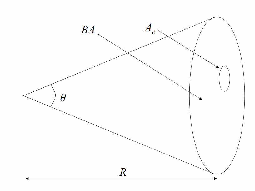
The area of the collecting system is simply given by:
(2)
where Dc is the collecting system diameter.
The power collected (Pc) is therefore given by:
(3)
where ta is the atmospheric attenuation and may be approximated by:
(4)
where σ is the atmospheric attenuation coefficient and may be characterised as σ = 0.2 km-1 on a good day and σ = 0.7 km-1 on a bad day.
The power collected (Pc) must be detectable by the system therefore:
(5)
where S/N is the signal-to-noise ratio (the lower this value the higher the likelihood of false alarms) and NEP is the noise equivalent power of the detector used (values for the NEP may be found in any detector manufacturer’s literature). This also assumes that all the power collected is coupled into the detector.
Hence the required laser power may be written as:
(6)
or:
(7)
If on the other hand the collector is greater in extent than the laser beam then Equation (3) reduces to:
(8)
and Equation (7) reduces to:
(9)
Laser-designator/target-marking systems
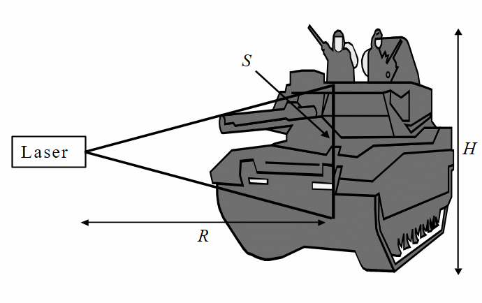
A laser-designator or target-marking system ‘illuminates’ a target, this radiation is then scattered (diffuse reflection) by the target and it is this scattered radiation that is picked up by, for example, a laser-guided munition. For successful designation the laser ‘spot’ at range R should typically be smaller than the target, see Figure 3; that is, S≤H where H is the target minimum dimension. Therefore:
(10)
The power at the target (Pt) can therefore be given as
(11)
The target then scatters this radiation into a hemisphere (a solid angle of 2π steradians, assuming at this point that the target is effectively a two dimensional object). A measure of the target’s diffuse reflectivity can be obtained from Kirchhoff's law:
(12)
where ε is the emissivity and because the surface finish of a military vehicle is likely to be rough, with respect to the wavelength, ε is likely to be high, hence a value of r=0.1 would not be unreasonable.
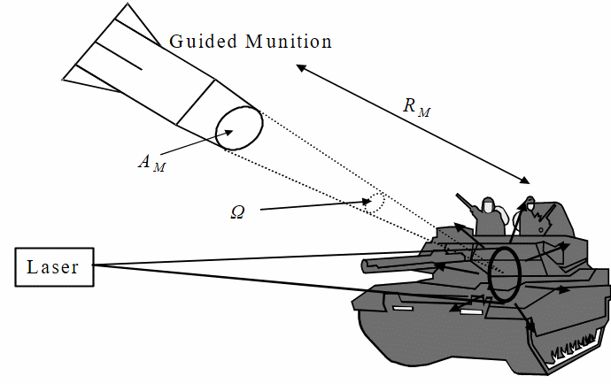
Some of this scattered radiation is then intercepted by the collector (lens) on the guided munition—see Figure 4.
Assuming the target acts as a Lambertian object then the scattered power per unit solid angle (Ps) can be expressed as
(13)
Hence the power collected (Pc) by the munition is
(14)
where Ω is the solid angle subtended by the collector of the munition and may be expressed as:
(15)
(16)
and:
(17)
Once again this must be detectable, that is:
(18)
and therefore solving for the required laser power gives:
(19)
General comments
Laser wavelengths. These would typically be from visible wavelengths (λ∼0,5µm) to the far infrared (CO2 laser λ=10.6µm) with the neodymium yttrium aluminium garnet (NdYAG) laser being the most prolific (λ=1.06µm).
Pulsed lasers. The laser sources used will typically be pulsed systems allowing for either/and/or high peak powers, range finding applications, coding and electronic countermeasure capabilities.
Atmospheric compatibility. The laser wavelength may be different from the wavelength of operation of the surveillance and target acquisition systems used (the fire post sight for example). This can have profound implications under certain atmospheric conditions, usually bad weather, when perhaps the target can be detected by the surveillance device but not designated with the laser and vice versa. Examples of this are aircraft targeting pods, where the surveillance and target acquisition device is a far infrared thermal imager (λ=8–14µm) with a NdYAG laser designator (λ=1.06µm) where the ‘gunner’ can ‘see’ the target through light cloud but can not achieve successful laser designation. Commonality of waveband of operation would go some way to alleviating this problem.
Laser-designation/target-marking (Equation 19). In these systems the laser energy is scattered off the target leading to indirect illumination of the detector in the munition, which leads to:
- A requirement for a sensitive detector.
- A requirement for a high-power laser, which is then easy for an enemy laser-warning receiver to detect.
Laser-beam riding (Equation 7). In these systems the laser energy directly illuminates the detector in the munition, this leads to:
- A requirement for a less sensitive detector.
- A requirement for a lower power laser, which is then more difficult for an enemy laser warning receiver to detect.
- The laser is bore-sighted with the firing post, but paints an information field of greater angular extent than the laser beam itself, this is usually coded to enable the munition to work out its position relative to the bore sight (aim point).
- The transmission of the laser information through any rocket motor efflux of the munition can be problematical, especially if the munition is powered by a boost-sustain motor (that is, the efflux is present throughout the complete engagement).
Summary
The above low fidelity model simply yields a few straightforward equations, which can be used to evaluate the likelihood of successful utilisation of the laser system of interest. Values for (or good estimates of) the variables in the equations can easily be found from manufacturers data sheets, photographs of equipment, or even web sites. It is very unlikely that the exact performance of the real equipment will be determined, but more often than not the results obtained are surprisingly close and demonstrate the power of low fidelity modelling when coupled to sound ‘engineering estimation’.
Bibliography
[1] M. Richardson et al, Surveillance and Target Acquisition Systems, Brassey’s Land Warfare Series, 1997.
[2] J. Accetta and D. Shumaker (eds), The Infrared and Electro-Optical Systems Handbook, SPIE Press, 1993.
Mark A. Richardson is head of the Electro-Optics group at the Royal Military College of Science, Shrivenham, England.