
Volume 5, Number 2, July 2002
Experimental Observations of the Perforation of Glass by the 7.62-mm NATO Ball Round
- 1 Both authors are with the Cranfield University, RMCS Shrivenham, Swindon, SN6 8LA, UK.
Abstract
An experimental programme was conducted to investigate the mechanics of perforation of the 7.62-mm NATO Ball round through multiple glass array. Two separate experimental trials were conducted using a multiple glass array as a target. In the first experiments, the spacing in between the glass plates and the areal density were varied. In the second trials, the plates had no spacing in-between and the areal density was fixed. Results indicating the nature of the penetration mechanism are presented with specific reference to the formation of the cone of comminuted glass that propagates from the front plate subsequent to its perforation.
Introduction
To date, almost all bullet-resistant glass comprises glass laminates with rubbery interlayers (such as polyurethane or polyvinylbuterate (PvB)) and a polymer as a backing layer, usually polycarbonate. The interlayers provide a flexible separation between the layers of glass and serve to contain the glass array. The backing layer is used to prevent spall at the rear face of the target. Depending on the threat level, different combinations of these layers form an array to prevent perforation by the projectile. While manufacturers do trial different materials, few manufacturers in the world are deviating from this basic approach. For these types of transparent armour systems, the penetration and subsequent perforation mechanics is fairly well documented.
What is lacking however, is an understanding of the perforation mechanics of spaced glass systems where arrays of glass are constructed with air gaps in-between (such as a common double-glazing system). This paper presents an experimental programme that describes the perforation of a 7.62-mm NATO Ball round through multiple-glass arrays (spaced and non-spaced). It is the authors’ intention to show that the perforation mechanics are significantly affected by even small changes of the construction of the glass system.
Because it was the authors’ intention to test principles rather than optimise a specific transparent armour system, all experiments were conducted without the use of any adhesive layer and confinement.
Experimental programme
For this programme, two separate experimental trials were carried out.
In the first set of trials, the areal density and the spacing in-between glass plates were varied. Four float glass plates (supplied by Pilkington plc) were used, spaced at 0.0, 1.5, 2.5 and 5.0 mm by gluing aluminium spacers at the four corners of the plates. For each system the thickness of the plate remained the same while the spacing between the individual plates was varied. The thicknesses under investigation were 3, 4, 6, 8 and 12 mm. Each plate had a cross-sectional area of 120-mm´120-mm square.
Furthermore, a second experimental trial was undertaken using plates of thicknesses 2, 5 and 10 mm. This time the plates were tested with no gap and the areal density of the glass was kept constant. The target arrays were arranged as three different systems, 3×10-mm, 6×5-mm and 15×2-mm plates with a constant areal density of 75 kg/m2. Each experiment was repeated twice. A diagram showing the typical target configuration for each trial is shown below in Figure 1.
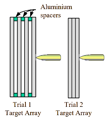
In each experimental trial, no adhesive or cover plate material was used.
For each target configuration a 7.62×51 mm NATO ball round (nominal mass=9.65g) was fired at the centre of the plates using a standard 7.62-mm proof barrel. The measured velocity of the round was 809±10 m/s. A CORDIN model 220 high-speed digital camera was used to record the perforation of the plates. A measurement of the front ejecta formation was carried out on the image captured at a nominal time of 500 µs after impact.
Observations
On impact, the glass material in contact with the projectile fails due to shear-induced microcracking. Due to the relatively low fracture toughness of float glass, only a small proportion of the kinetic energy of the projectile is transferred to the glass for the generation of new fracture surfaces. Instead, a far greater proportion of the kinetic energy is transferred into kinetic energy of the glass fragments.
At the front surface a “splash” of comminuted glass occurred as the projectile penetrated into the first glass layer. This material continued to expand radially and in the opposite direction of travel to the penetrator. Later, as subsequent layers of glass were perforated, an inverse conoid of comminuted glass began to form.
Figure 2 shows the comparison of comminuted glass that is ejected from the front plate, for four glass plates with zero spacing. The projectile is travelling from right to left. The bulk of the ejected material forms the shape similar to an inverse cone. The comminuted material from the initial impact “splash” can be seen to the right in Figures 2 (b) and (c).
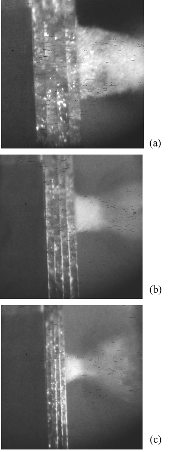
The measured geometry of the cones of glass formed are summarised in Table 1 with reference to Figure 2. Unfortunately, we were unable to record cone formation data for the 4×12-mm and 3×10-mm plates.
| Target array | θ (degrees) (see Figure 3) | A (mm) (see Figure 3) |
|---|---|---|
| 4×4-mm plates | 17.5 | 23.8 |
| 4×6-mm plates | 13.5 | 32.0 |
| 4×8-mm plates | 19.0 | 59.1 |
| 4×12-mm plates | N/A | N/A |
| 15×2-mm plates | 20.7 | 38.7 |
| 6×5-mm plates | 12.1 | 35.7 |
| 3×10-mm plates | N/A | N/A |
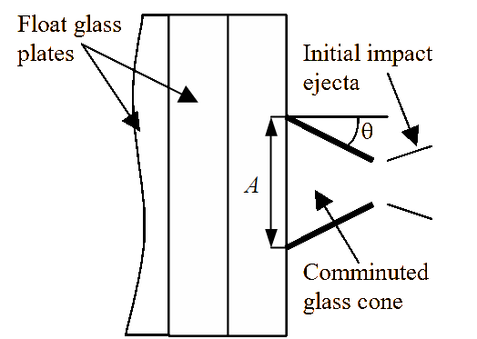
This characteristic inverse cone formation was observed in all targets that had no spacing in-between each of the glass plates.
Introducing a space in between each plate results in a reduction in the amount of glass that is ejected via the front plate. Figure 4 below shows the resulting comminuted glass formation that results from introducing a space.
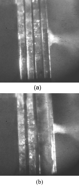
Introducing a 1.5-mm space in between the plates resulted in the formation of an inverse cone. The data for these comminuted cones are provided in Table 2:
| Target array | θ (degrees) (see Figure 3) | A (mm) (see Figure 3) |
|---|---|---|
| 4×4-mm plates | 13 | 15.4 |
| 4×6-mm plates | 40 | 26.0 |
| 4×8-mm plates | 61 | 36.5 |
| 4×12-mm plates | 42 | 51.4 |
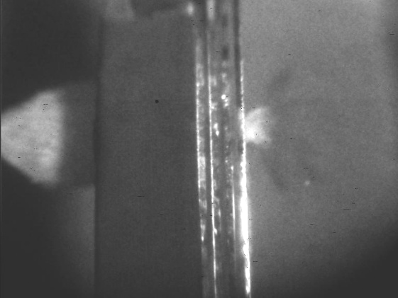
Very few inverse cones were formed with target arrays with spacing of 2.5- and 5.0-mm. In all of these cases, the perforation of the array resulted in a characteristic “splash” as shown in Figure 5.
Discussion
Insight into the formation of the inverse conoid is provided by the evidence provided by the high-speed photographs:
Firstly, it was observed that increasing the spacing in between each of the plates generally stopped an inverse cone being formed and reduced the amount of glass that was ejected from the front plate. This evidence suggested that for arrays with a space of 2.5 and 5.0mm in-between each of the glass plates, the comminuted glass that was formed by each successive perforation dissipates into the space in-between the glass plates instead of forcing its way through the perforated front plate. In other words, the comminuted glass followed the path of least resistance.
Secondly, it was noted that increasing the thickness of the glass plates resulted in an increase in the base (measurement ‘A’) of the inverse cone formation for both the arrays with 0.0- and 1.5-mm spacing in between the plates. This indicates that thicker glass plates or, the greater the quantity, results in larger amounts of comminuted material escaping from the front of the target array.
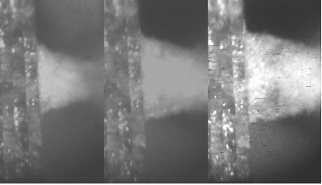
Thirdly, the size of the inverse cone’s base grew over time as each successive plate was perforated and the comminuted material that was formed pressed its way through the path of least resistance. Figure 6 below shows an example of this phenomenon with an array of four glass plates with no spacing in-between each of the plates. Over a period of 325 µs, the cone’s base size, A, grows from 43.1 mm to 59.1 mm.
Fourthly, the measured angle for the inverse cone that was formed varied little with the array’s thickness for glass plates with no spacing but was influenced greatly by introducing a space in-between the plates (see Table 2). The probable reason for this is because the comminuted “splash” that is formed from the second and subsequent plates can expand radially and relatively unhindered before coming into contact with the preceding plate. Therefore, the backward flowing comminuted material from the second plate has the freedom to affect the damaged front plate at a larger diameter than would be expected if there was a smaller gap in-between. Each subsequent plate that is perforated releases a wider diameter of debris due to a larger contact area (see later).
Most of the comminuted material is dissipated by the spaces and the spacing also reduces the amount of backward flowing comminuted material. Therefore the overall amount of comminuted glass formed and ejected from the front place is significantly less than what is observed with arrays of glass plates with no spacing. For arrays with a spacing in-between the glass plates of 2.5 and 5.0-mm, few cones were observed.
The preceding evidence suggests that the penetration and failure of each of the glass plates is governed by the formation and dissipation of the comminuted material. From the qualitative and quantitative evidence presented the authors suggest that the penetration mechanism of the 7.62-mm NATO ball round through glass arrays can be described as follows:
After perforation of the front plate, a crack propagation wave (damage front) extends radially from the centre leading to the plate’s structure being compromised. At the same time, the comminuted glass is being formed and compressed against the second plate with some material escaping in the opposite direction to that of the projectile.
As each successive plate is penetrated, the projectile is blunted. Moreover, the comminuted glass is compressed into the front of the projectile forming a relatively large contact area with the unbroken glass plates. This increase in the contact area results in a larger distribution of contact pressure (according to Hertzian theory [1]) resulting in a larger degree of contact damage to subsequent plates. This phenomenon has been observed in numerical simulations [2]. Due to the confinement offered by subsequent plates, the comminuted material that is formed is then forced to flow in the opposite direction to the projectile (see Figure 7).
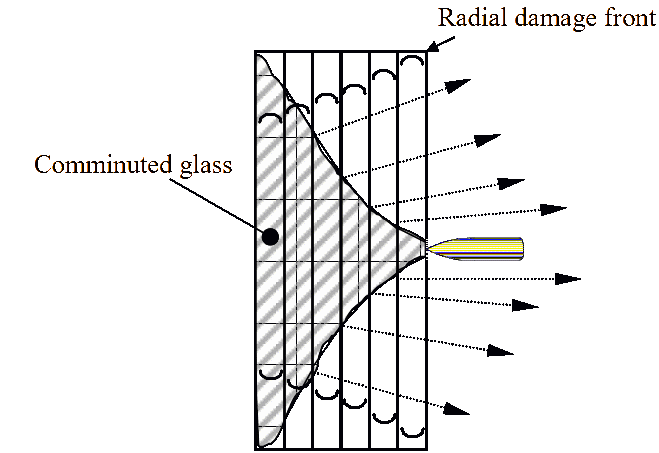
The now broken plates behind the progressing projectile succumb to the pressure of the comminuted material, the diameter of which is growing larger with each successive plate perforation. This gives rise to the formation of the inverse cone that is seen in Figures 2, 4 and 6.
As the projectile perforates each successive plate very little in-plate damage can be observed via high-speed photography as the glass is comminuted and therefore its refractive index is changed [3].
The 7.62-mm NATO Ball round was stopped by 4´12-mm glass plates (all spacings). This corresponds to an areal density of 121.4 kg/m2.
Unfortunately as the glass arrays were unconfined, extensive fragmentation prevented any meaningful post perforation data being acquired.
Conclusions
An experimental programme has been conducted to evaluate how a 7.62-mm NATO ball round perforates a multiple glass system.
The mechanics of perforation are affected by the degree of spacing between each successive plate. The main influence on the projectile is the formation and dissipation of the comminuted glass. Where spacing exists, the comminuted material is able to flow in-between the glass plate resulting in a clearer path for the projectile. Where is there is no spacing, the confinement of subsequent plates forces most of the comminuted glass material to flow in the opposite direction of projectile travel.
In all arrays with no spacing in-between each of the glass plates an inverse cone shape formed at the front plate was observed. This is due to the progressive nature of the failure that occurs as each plate fails due to the penetrating and deforming projectile. The failed glass in turn causing a larger footprint on the subsequent plate.
Acknowledgements
The authors would like to Mr Dave Miller for assisting with the firing trials. This project was undertaken for Capt Armstrong’s Military Vehicle Technology MSc with contributions from Mr Paul Winks’ Forensic Engineering and Science MSc dissertation. This work was partly funded by the Nuffield Foundation.
References
[1] H. Hertz, “On the Contact of Elastic Solids”, J. Reine Angew. Math, Vol. 92, 1882, pp. 156-171.
[2] S. Armstrong and P. Hazell, “Perforation of Glass Systems by the 7.62mm NATO Ball Round”, Proceedings of the Light Armour Systems Symposium, Royal Military College of Science, Shrivenham, UK, 3-5 Oct 2001.
[3] A. Prengel, High Speed Photography of the Penetration of Face-Covered Glass Blocks, MVT MSC Project Report, Royal Military College of Science, Shrivenham, UK, July 1999.