
Volume 3, Number 1, March 2000
Warhead Hit Distribution On Main Battle Tanks In The Gulf War
Abstract
After the Gulf War, 308 armoured vehicles were inspected to investigate the damage caused by kinetic energy (KE) rounds and shaped charge (SC) warheads. The resulting data is analysed and compared to data from World War II 1944/45, the 1967 Six-day War, the 1983 Yom Kippur War as well as with the hit distribution data used by Germany, the USA and the UK for tank design and vulnerability prediction. It is shown that none of these correlate with the Gulf War data. Analysis is also conducted of the Coalition ammunition used and it is shown that the KE rounds (from type 3 on) and the SC warheads (from type 2 on) were overmatched to the T55, T62 and T72 tanks used by the Iraqi forces.
Introduction
As a weapon designer, especially of shaped charge warheads, the author had a great interest in seeing what damage shaped charge hits can create on real targets such as fully equipped tanks, as well as observing the difference in perforation achieved by kinetic energy (KE) rounds and shaped charge (SC) warheads.
Warhead hits on armoured vehicles are commonly assumed to be distributed according to Whittaker’s direction probability variation (DPV) or the elliptical distribution [1] (see Figure 1), both of which indicate that the frontal arc is more likely to be hit compared to the other tank surfaces. This paper analyses whether these standard rules are confirmed by the Gulf War or whether different distributions have to be taken into account, at least for this war.
![Whittaker’s DPV [1].](/journals/journal-of-battlefield-technology/volume-03/issue-01/assets/3-1-1-held/figures/figure01.gif)
Background
After the Gulf War, the company CMS won the contract to clear the sector from “war waste” such as vehicles (tanks, APCs, trucks and so on) as well as ammunitions and mines. An enormous number of different articles were collected. The destroyed tanks and vehicles were brought to a special collection place called the “CMS depot”, and the undestroyed tanks and APCs were collected on the “fair ground”, as shown in Figures 2 and 3 respectively.
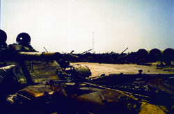
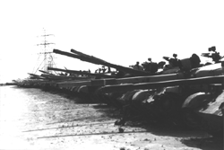
Both of these collections were carefully searched by the author for hits from all horizontal sides and from the top. At the fair ground, 110 undestroyed armoured vehicles had been collected including 6 tanks that had hits without any damage. At the CMS depot, 116 tanks, 45 hulls without turrets and 37 separate turrets were found, with about 40% having hits. Note that, for the 82 turrets and hulls in this total, the missing parts might have been hit, which must be taken into account.
The following two examples illustrate the located target hits and their analysis.
The hits could easily be judged to be caused by KE rounds or SC warheads. The holes produced by KE rounds are produced by long-rod penetrators, also called armour-piercing, fin-stabilised, discarding-sabot (APFSDS), where the fin traces around the hole give a clear signature. Further, the holes have a constant diameter with relatively smooth surfaces along the inner perforation path.
SC warheads leave characteristic traces of fragments produced by the casing on the outer surface. Small scratches are produced by fragments of the thin aluminium casings of missile warheads and much deeper craters are produced by the steel fragments of HEAT rounds fired from tank guns.
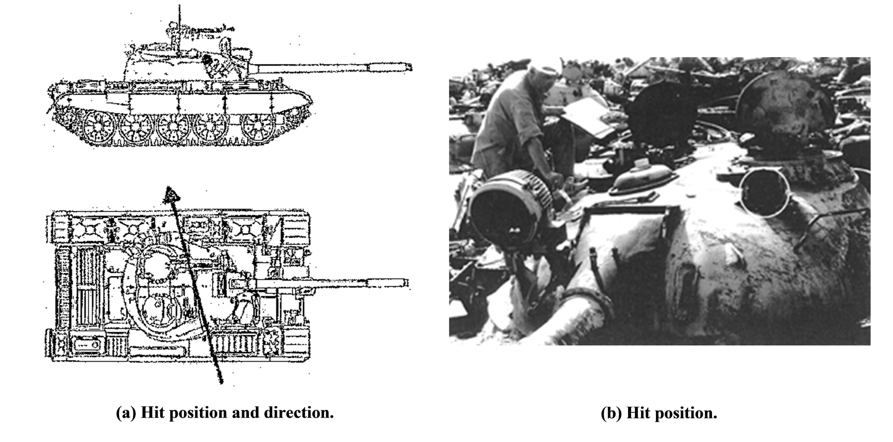
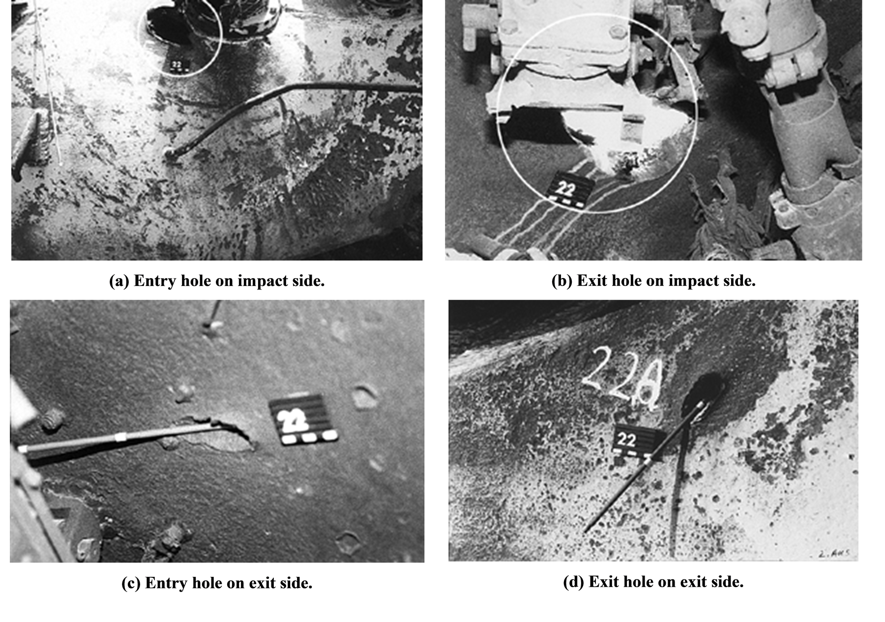
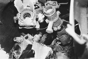
The first example is a KE round hit on the turret of a T55 tank (target number 13). Figure 4(a) shows the hit position on the top of the turret and the azimuth hit direction. Figure 4(b) is a full picture of the turret itself, where the hit position is highlighted by a circle. That the hole was produced by a KE penetrator is clearly demonstrated by Figure 5(a), which shows the two cuts made by the fins when passing through the tubular handle. The crater is conically widened as shown in the Figure 5(b). The penetrator passed completely through the turret and exited on the other side; the entrance and exit holes are visible in the lower pictures of Figures 5(c) and 5(d).
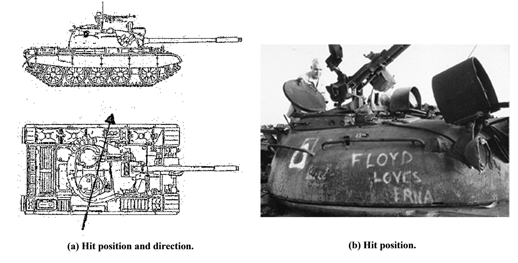
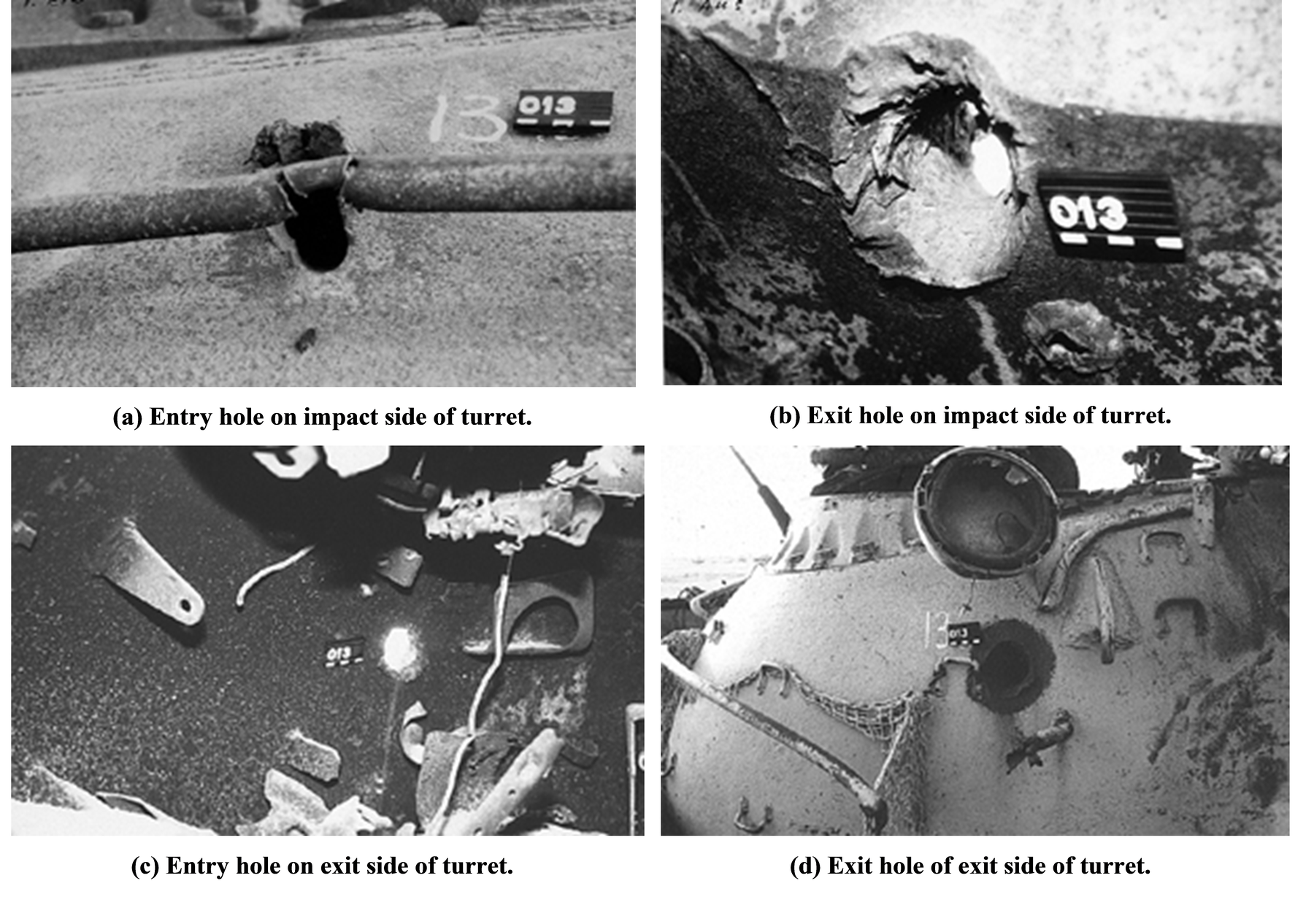
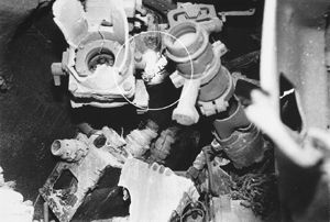
Figure 6(a) shows the second example of a hit on the turret top of a T55 tank (target number 22). The SC jet also perforated the turret, as shown in Figure 6(b), which does not clearly show the entrance hole. It is remarkably large, which is still not very obvious in Figure 7(a). However Figure 7(b), taken from inside, shows that the hole is more than 100 mm across. The black and white scaling on the magnetic holder for the target number is 5 cm in length. The entrance and exit hole on the other side of the turret is again presented in Figures 7(c) and 7(d). The rods are marked at 100 mm intervals and are used to obtain the thickness of the perforated armour, and to determine the hit directions, also shown on the pictures. The damaged optical sights for the gunner, along with the entrance hole in the background, are visible in Figure 8.
Analysis procedure
The analysis began with numbering the targets that had been hit. A few targets received several hits more or less from the same direction, indicating that they had been used as training targets. If one target showed more than one hit, the different shots received letters a, b, c and so on. The following graphs are sub-divided into the analysis of “hits” in which all hits are used, and “targets” where only one representative hit on one target was selected. In total, 156 “hits” were found, but only 78 were analysed as “targets” hit by shaped charges or KE rounds.
For the analysis a list was prepared of the following:
- target number;
- type of tank;
- type of ammunition (KE or SC);
- hit location (turret left etc. and vertical distance to the turret ring); and
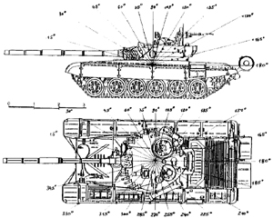
- azimuth and elevation angles (see Figure 8).
- dimensions of the hole including:
- impact diameter,
- channel length,
- exit diameter,
- distance to a second impact or perforation,
- measurement of the crater geometries, and
- remarks.
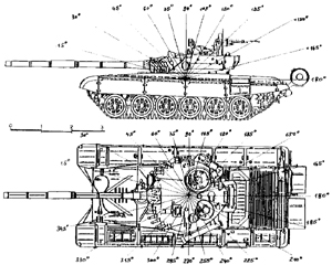
Pictures were taken of the entrance and exit side of each hole, mostly with a rod marked at every 100 mm intervals to give an indication of the directions or angles. In azimuth, 0° was chosen as the forward direction of the hull, and the firing orientation of the gun for the analysis of hits on the turret. The azimuthal distribution was measured clockwise. As illustrated in Figure 9, in the elevation direction, 0° was horizontal and 90° was vertical.
Analysis of hole diameters
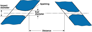
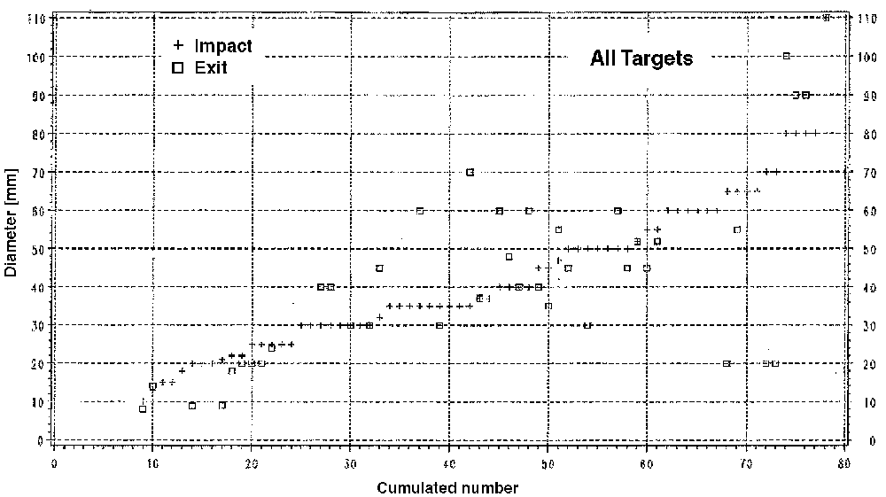
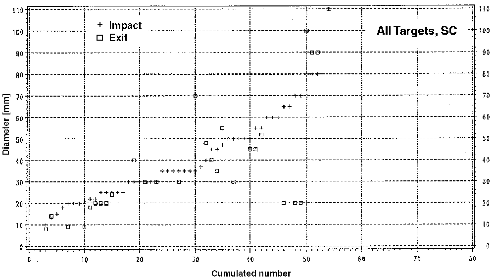
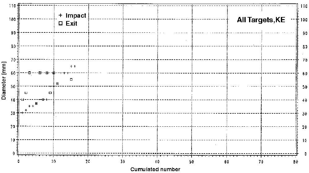
To obtain the relevant values of the crater the diameters were measured between 10 mm and 20 mm from the entrance and exit surface (Figure 10). Figure 11 shows the cumulative number of targets (not hits) for which entry hole diameter exceeds a given value. Data for the corresponding exit holes is also shown, where it is different. Figures 12 and 13 show the same data, but separated according to whether the hit was judged to be due to a KE round or a SC warhead. For KE rounds the exit diameters were typically between 40 mm and 60 mm, but not more. This value is also achieved by about 50% of the shaped charges, but sometimes much bigger holes are found especially if thinner target plates are hit on the roof.
Analysis of the hit distribution in elevation
In an enthusiastic article, Kennedy [2] describes the power and effectiveness of the small bomblets M42, M46 or M77 DP/ICM (Dual Purpose/Improved Conventional Munition) fired and delivered 88 sub-munitions with the M483 A1 155 mm projectiles, 180 with the M509 A1 8-inch (203 mm) projectiles and 644 grenades with the M26 MRLS (Multiple Launch Rocket System) warhead. He states that tens of millions of these grenades were delivered. In the light of this and many similar reports, the author particularly searched for small holes or for the expected signatures from the fragment casings on the top of the tanks and turrets, but nothing of this kind was identified. Indeed, no hit with an elevation angle greater than 10° could be found.
This is, perhaps, not surprising since KE rounds generally have horizontal straight line trajectories. Even a HELLFIRE missile launched from a helicopter at a range of 2000 m and at a height of 200 m would only give an angle of 5.7°.
Analysis of the hit distribution in azimuth
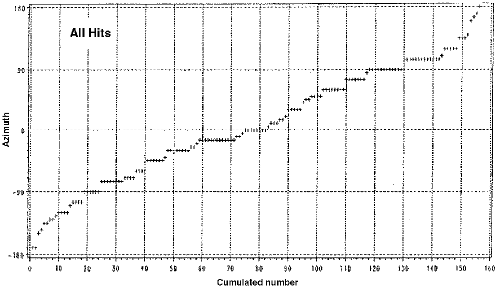
The azimuth distribution of all hits (not selected to targets) counted clockwise is summarised in Figure 14. As mentioned before, a few targets had many hits from the same direction, and were probably used as training targets. Therefore, the distribution is also shown only for the 78 investigated targets (Figure 15). The straight line shows that the hit distribution is not uniform over the 360°, but is approximately linear between ±135°. There are fewer hits only on the rear section (Figure 16). This is accentuated by the higher number of shaped charge hits (Figure 17) while with KE rounds, only one hit was in the frontal arc. All the others are over more than ±45° (Figure 18).
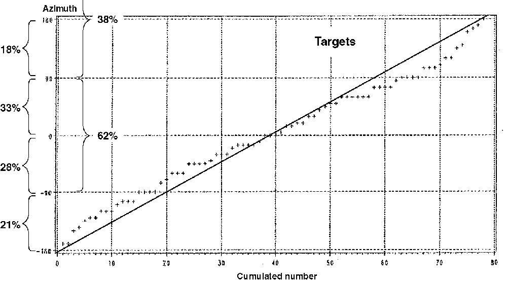
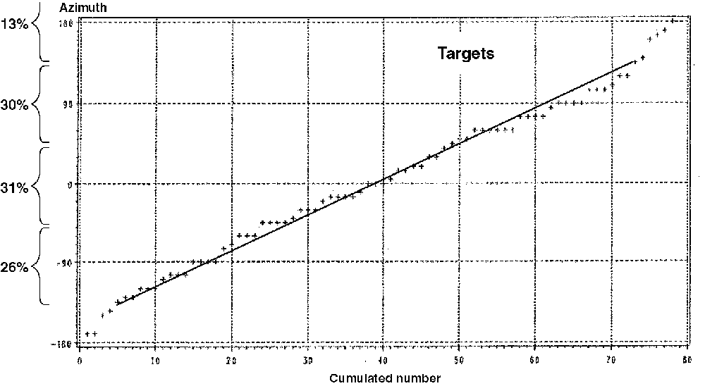
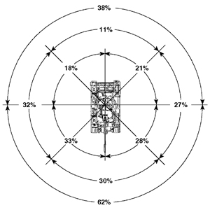
The analysed azimuth hit distribution is expressed in a polar diagram in Figure 19. 62% have hit the front semicircle and 38% the rear semicircle, or 30% the ±45 quadrant, 32% the right and 27% the left quadrant and 11% from behind.
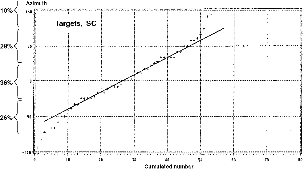
Figure 20 gives the percentages of both values, for targets and total hit numbers. The values do not deviate too much from one another and they do not change the total assessment to any great extent.
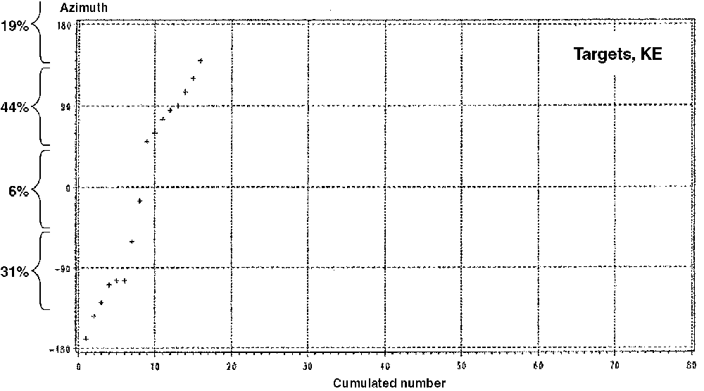
The azimuth distributions of the hits by SC warheads and KE rounds are compared in Figure 21. The real number of hits counted in the individual quadrants is indicated in brackets which demonstrates that the numbers are too small to obtain a statistically meaningful distribution.
Conclusions
A total of 308 armoured vehicles were inspected; about 25% of them were damaged.
The following tanks were found with hits:
- 65% T55,
- 17% T62, and
- 18% T72.
The hits were caused by the following
- 70% SC,
- 20 % KE rounds, and
- 10% others.
Damage by “other” effects are not discussed in this paper.
77% of the hits are against the turret, which is much more than on the hull (23%). The reason for this is most likely that the tanks are generally dug-in in trenches, so that the hulls were not exposed to direct hits.
Surprisingly low are the “hits on the targets” in the frontal arc or ±45° quadrant with 30%, compared to the side hits (±45° to 135° sector) with 32% from the right and 27% from the left and 11% from behind in the ≥135° sector.
Conclusions Drawn by W. Paul [3]
Paul [3] from CONDAT, , analysed these results with earlier events. He compared a analysis of World War II 1944/1945, the Six-Day War in 1967, and the Yom Kippur War in 1983, which are all mirrored at 0° or symmetrically arranged, with the distribution of the Gulf War results (Figure 22).
![Azimuth hit distributions analysed for World War II, Six-day War and Yom Kippur War in Israel and the azimuthal distribution found in Gulf War [3].](/journals/journal-of-battlefield-technology/volume-03/issue-01/assets/3-1-1-held/figures/figure22.png)
Not all countries use the same azimuth hit distribution data for tank design and vulnerability predictions. The data used by , the and the are shown in Figure 22. None of these correlate with the Gulf War data of Figure 21.
But Paul also made a comparison of the vertical hit distributions, measured always to the turret ring, expressed as mean values for different types of tank and ammunition. From the Six-Day war to the Yom Kippur War to the Gulf War, fewer and fewer hits are counted in the hull and more and more hits are recorded on the turret (Figure 24).
![Predictive azimuthal hit distributions used to evaluate the single shot kill probability (SKP), after [3].](/journals/journal-of-battlefield-technology/volume-03/issue-01/assets/3-1-1-held/figures/figure23.png)
![Analysed vertical hit distributions of the Six-day War and Yom Kippur War in Israel to the analysis in the Gulf War [3].](/journals/journal-of-battlefield-technology/volume-03/issue-01/assets/3-1-1-held/figures/figure24.png)
Paul also compared the performance of the different KE round generations with 0° and 60° impacts and the performance of shaped charges with respect to the line-of-sight separately expressed for the hulls and turrets of the engaged tanks T55, T62A and T72 (Figure 25). Figure 26 shows that the most commonly used KE type 5 rounds with 525 mm to 555 mm perforation capability, and at least type 2 SC, always perforated the armours with high overmatch. He declares that in the Gulf War the ammunition was superior to the armour on the tanks engaged and defeated. Or in other words it was demonstrated that the APDS-FS rounds of the 105 mm and 120 mm gun, and the shaped charges of TOW1, TOW2, HOT and HELLFIRE, are superior weapon systems when used against the obsolete or out-of-date Iraqi tanks such as T55, T62A and T72.
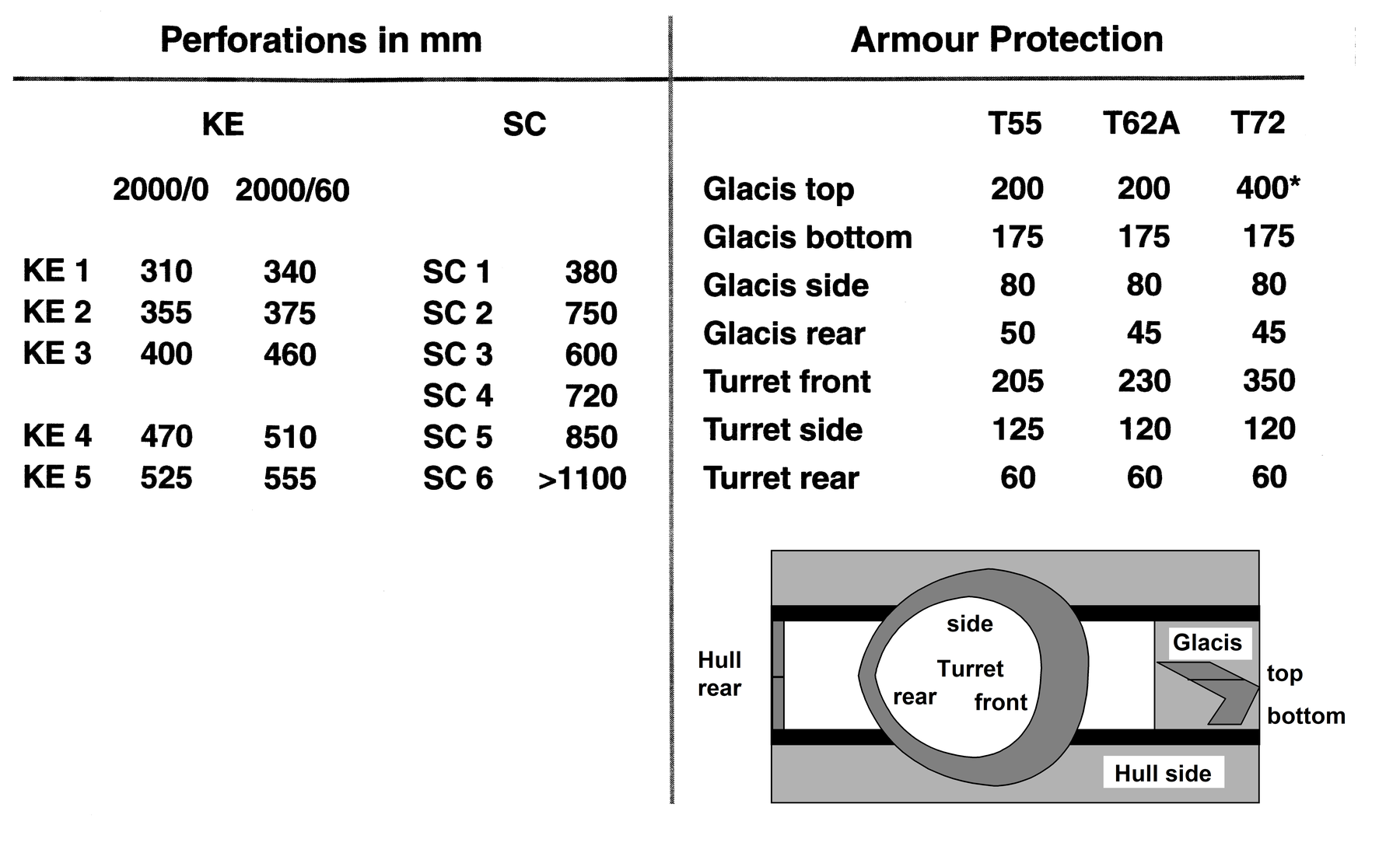
![Relation of the performance of the used KE rounds and SC (HL) compared to the turret front and the top armour glacis of the T55, T62 and T72 after [3].](/journals/journal-of-battlefield-technology/volume-03/issue-01/assets/3-1-1-held/figures/figure26.png)
References
[1] T. Terry, S. Jackson, C. Ryley, B. Jones and P. Wormell, Fighting Vehicles, Brassey’s Vol. 7, pp. 125-127.
[2] D. Kennedy and , “Steel Rain: Submunitions in the Desert”, Army, Vol. 43, pp. 24-31, 1993.
[3] W. Paul, CONDAT, Maximilianstr. 28, 85298 , Tel: 49 8083 546 578, Fax: 49 8083 546 576.