
1.2 A SIMPLE COMMUNICATIONS SYSTEM
A communications system conveys information from one point to another (across a channel) through a structured set of functional elements—the four basic elements are source, transmitter, receiver, and sink. The block diagram of a simple communications system is shown in Figure 1.1. For the moment we are concerned with a one-way communication process: from the originator of the information to the recipient (from the source to the sink). Later we look at communications systems that pass information amongst many participants but, for the moment, these can simply be considered as variations of the basic system shown in Figure 1.1.
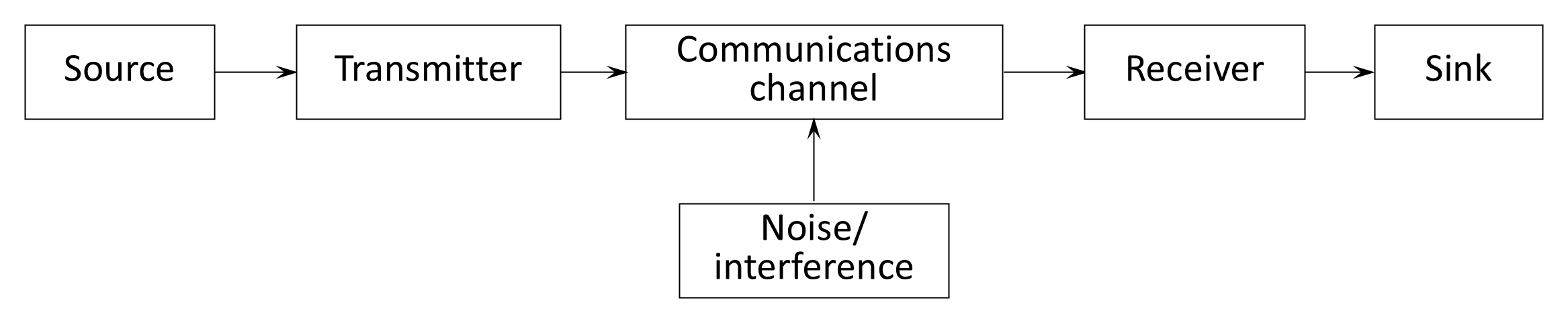
Source. The source is the originator of the information that is to be exchanged through the communications system. The source converts the original message information (in sound, text, or image format) into an electrical signal. For voice, the source normally uses a microphone to convert the sound waves generated by the human speaker into electrical signals. Text is converted to electrical signals through a teletypewriter or computer. Images are captured through a still or video camera.
Transmitter. The transmitter processes the input signals into a form suitable for transmission across the communications channel. This processing involves some form of conditioning, coding, amplification, and frequency translation. We discuss each of these functions in the next section and in the remaining chapters but, for the moment, Figure 1.1 combines the major functions of the communications system in the transmitter and receiver stage. In practice, a transmitter or receiver stage consists of more than one device.
Communications channel. The communications channel is the electrical medium that connects the transmitter to the receiver. It can be a pair of wires, a coaxial cable, a metal waveguide, a fiber-optic cable, or a radio or light wave. The type of communications channel will be chosen carefully for a particular application. Later we discuss different types of communications channels and the features that affect their suitability.
Noise and interference. As a signal is transmitted across the communications channel it can be mixed with other unwanted signals accumulated from a variety of sources. These unwanted signals are called noise and interference. Noise is introduced into the channel by natural sources; interference is introduced by man-made sources. Although noise and interference can be accumulated from a variety of sources, it is often useful to consider a single source that represents the sum of all the various sources of unwanted signals. As shown in Figure 1.1, it is also normal to consider that noise and interference are introduced by the channel and that the transmitter and receiver are ideal (noise-free) devices.
- Noise. Noise refers to random and unpredictable electrical signals produced by natural processes, both internal and external to the communications system. Internal noise can be caused by the heat energy of the molecules in each component in the system (called thermal noise), noise generated within semiconductor devices (called shot noise), and noise due to mechanical flaws and weaknesses such as a poor solder joint. External noise is due to atmospheric effects caused by disturbances such as thunderstorms, and solar and galactic noise caused by electromagnetic radiation from the sun and galaxy respectively.
- Interference. Noise can also be exacerbated by interference, which is produced by human-made sources such as transmitters from other communications systems, from power lines, and even from some machinery. Human-made interference is predominantly in the frequency range of 15–160 MHz.
Receiver. The receiver extracts the signal from the communications channel and passes it to the sink. The receiver functions will depend on the transmitter functions at the other end of the communications channel. If the transmitter performed modulation and coding, the receiver demodulates and decodes; and so on.
Sink. The sink converts the electrical signal from the receiver back into the form of the original message information. For voice, the sink is a loudspeaker that converts the electrical signal into sound waves for aural reception. For text, a teletypewriter produces words on a piece of paper, or a computer displays words on a screen or stores them in some form. A television is used to display the series of images contained in video signals.
The simplicity of this model provides a useful foundation for understanding the more complex communication architectures introduced in subsequent sections, where multiple users, duplex transmission, and signal processing stages are incorporated. Yet even this simple model hides a significant degree of internal structure. Each of the functional blocks in Figure 1.1 —source, transmitter, channel, receiver, and sink—comprises several subordinate processes that together ensure the reliable transfer of information. The next section begins that process by elaborating on the simple diagram to show how these internal processes combine to form a more-detailed (and therefore a more-useful) communications system.
Back to reading