
D LINE CODING
After source (data compression) or waveform coding (such as PCM or DPCM), the digital signal may be transmitted in its original form without carrier modulation. As described in Chapter 2, digital signals comprise a series of ones and zeros, each represented by a different voltage level. Although any two distinct voltage levels may appear sufficient in principle, the original baseband waveform is not well suited to direct transmission. Line coding converts the signal into a form better suited to the transmission medium by eliminating DC and low-frequency components (which waste power and hinder transformer coupling) and by embedding timing information that assists in synchronization.
As illustrated in Figure D.1(a), a logical zero could be represented by 0 V and a logical one by some positive voltage. This is called a unipolar or unbalanced code since the voltage excursions are all in one direction. Unfortunately, unipolar codes do not travel far, because the pulses are affected by line attenuation and cannot pass through transformers. Moreover, since the DC pulses are always positive, the technique is inefficient in its use of power.
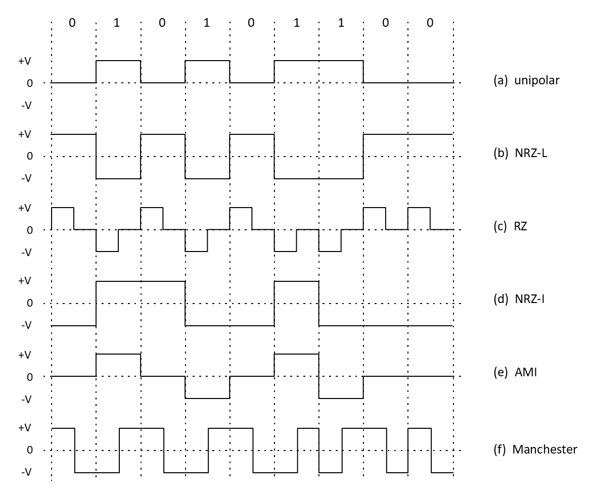
Bipolar, or balanced, codes address these difficulties by representing zeros by a positive pulse (typically between +5 V and +15 V) and ones by a negative pulse (between –5 V and –15 V). The average transmitted voltage approaches zero, and the transmission path can include transformer-coupled or AC-coupled circuits without signal degradation. These techniques are called non-return-to-zero (NRZ) schemes, and when a zero is represented by one voltage and a one by another, as shown in Figure D.1(b), the scheme is called NRZ-level (NRZ-L). While power-efficient, NRZ-L suffers from difficulty in maintaining synchronization during long strings of ones or zeros, when there are no transitions to realign the receiver’s clock. This can be overcome by inserting synchronization bits, although better methods exist.
Figure D.1(c) illustrates the bipolar return-to-zero (RZ) technique, which ensures that the signal returns to zero at the midpoint of each bit period so that the receiver always has transitions available for clock alignment. The main disadvantage is that the baud rate is twice the bit rate, meaning that twice the bandwidth is required to convey the same information.
A technique often referred to as differential encoding assists in clock synchronization by placing the information in the pulse transitions, as shown in Figure D.1(d). NRZ-inverted (NRZ-I) is such a scheme, in which a transition indicates that the next symbol is a one, while no transition indicates a zero. Although the scheme can exhibit a DC component when implemented unipolarly, the receiver has no difficulty maintaining synchronization during long idle periods.
A widely used form of line coding is alternate-mark-inversion (AMI), in which a zero is represented by zero volts and each successive one is represented by a transition of opposite polarity to the previous one. The alternating polarity of marks reduces spectral energy near DC and enables error detection through bipolar violations. Variants of AMI, such as HDB3 and B8ZS, are used in most major telecommunications networks.
There are three types of bi-phase codes: bi-phase-L, bi-phase-M, and bi-phase S:
- Bi-phase-L. Commonly known as Manchester coding, bi-phase-level (bi-φ-L) represents a binary one by a low-to-high transition and a binary zero by a high-to-low transition at the midpoint of each bit interval. Each bit period therefore contains a guaranteed transition, providing inherent self-clocking and eliminating any DC component. As a result, Manchester-coded signals can pass through transformers, exhibit relatively low baseline wander, and offer limited error-detection capability, since noise must corrupt both halves of a transition to mask a bit error. Manchester coding was used in early IEEE 802.3 (10 Mbps Ethernet) systems and IEEE 802.5 (Token Ring).
- Bi-phase-M. Bi-phase-mark (bi-ϕ-M) encoding introduces a transition at the midpoint of every bit interval for clock recovery, as in Manchester coding, but additionally includes a transition at the beginning of the bit interval to represent one binary state (typically a logical one), while the absence of this initial transition represents the other state. This scheme therefore conveys information through the presence or absence of a boundary transition, providing robust synchronization at the cost of increased transition density and, consequently, higher bandwidth requirements.
- Bi-phase-S. Bi-phase-space (bi-ϕ-S) encoding is similar in principle to bi-phase-M, except that the additional transition at the start of the bit interval represents the opposite binary state (typically a logical zero rather than a one). Like bi-phase-M, it guarantees regular transitions for clock recovery and eliminates any DC component, but it is less commonly used in practice, largely because it offers no fundamental advantage over bi-phase-M or Manchester coding in typical data transmission systems.
Each of these coding schemes can be characterized by its spectral occupancy, DC content, and self-clocking capability. Unipolar and NRZ-L signals are spectrally inefficient near DC and require additional timing recovery aids. RZ, NRZ-I, and Manchester coding improve synchronization robustness at the cost of increased bandwidth. AMI and its derivatives achieve DC balance and incorporate simple error-detection features that make them well suited to long-haul and carrier-network applications. The choice of line-coding technique therefore represents a compromise between bandwidth efficiency, power utilization, synchronization performance, and implementation complexity.
Many additional line-coding variants exist beyond those shown in Figure D.1, each optimized for specific transmission media or system constraints:
- Miller (Delay) Encoding: Each logical 1 is represented by a mid-bit transition, while a logical 0 produces a transition only at the start of the bit period if it follows another 0. This coding halves the DC component and provides sufficient transitions for clock recovery. Widely used in magnetic-stripe readers and early floppy-disk interfaces.
- 4B/5B and 8B/10B Block Coding: These are block line-codes that map groups of n data bits to n + 1 or n + 2 encoded bits. The mappings guarantee frequent transitions and DC balance. Used in Fast Ethernet (100BASE-TX), Fiber Channel, Gigabit Ethernet, and PCI Express.
- HDB3 (High-Density Bipolar-3 Zeros) and B8ZS (Bipolar with 8-Zero Substitution): These are scrambled extensions of AMI that insert controlled “bipolar violations” when long runs of zeros would otherwise occur. This ensures sufficient transitions for synchronization without increasing bandwidth. Used extensively in E-carrier (E1) and T-carrier (T1) telecommunications systems.
- Scrambled NRZ: Instead of fixed substitution rules, a pseudo-random sequence is XORed with the data to ensure spectral uniformity and eliminate long DC runs. Used in modern digital subscriber line (DSL) and optical transport systems.
- Multilevel Codes (e.g., PAM-3, PAM-4): These encode more than one bit per symbol by using multiple discrete voltage levels. For example, PAM-5 is used in 1000BASE-T Gigabit Ethernet, and PAM-16 is used in 10GBASE-T and later multi-gigabit copper standards. PAM-4 is widely deployed in high-speed optical Ethernet links (25 Gb/s per lane and above).
- Duobinary and Partial-Response Signaling: These intentionally introduce controlled intersymbol interference to narrow the signal spectrum, improving performance over band-limited channels. Applied in high-speed optical and magnetic recording systems.
- MLT-3 (Multi-Level Transmit-3): MLT-3 is a three-level signaling scheme used in 100BASE-TX Fast Ethernet. It operates in conjunction with 4B/5B block coding. Whereas 4B/5B ensures sufficient transition density for synchronization, MLT-3 reduces the spectral bandwidth of the transmitted signal. MLT-3 uses three voltage levels: +V, 0, and −V. Instead of assigning voltage levels directly to binary values, MLT-3 changes state only when a logical 1 is transmitted; a logical 0 produces no transition. The waveform cycles through the sequence: +V → 0 → −V → 0 → +V → …. Thus, consecutive ones cause the signal to step through this repeating three-level pattern, while zeros hold the current level unchanged. Because a complete cycle through the three levels requires four successive logical ones, the fundamental frequency component of the transmitted waveform is one-quarter of the data rate. This significantly reduces the required bandwidth compared with NRZ signaling at the same bit rate. The reduced spectral occupancy enables 100 Mb/s transmission over Category 5 twisted-pair cable without exceeding its bandwidth limitations. MLT-3 does not itself provide DC balance or guaranteed transitions; these properties are ensured by the preceding 4B/5B block encoding stage. Together, 4B/5B and MLT-3 enable Fast Ethernet to achieve 100 Mb/s while maintaining manageable electromagnetic emissions and signal integrity over copper cabling.
Each technique thus represents an engineering trade-off: unipolar and NRZ codes are simple and power-efficient but poor for long-distance transmission; RZ and Manchester codes enhance synchronization at the cost of bandwidth; AMI, HDB3, and B8ZS achieve DC balance for long copper links; and multilevel or block-encoded schemes serve today’s very-high-rate fiber and backplane applications.
Back to reading