
B.4 CIRCUIT COMPONENTS
Figure B.5 shows the symbols for the circuit components of resistance, capacitance and inductance.
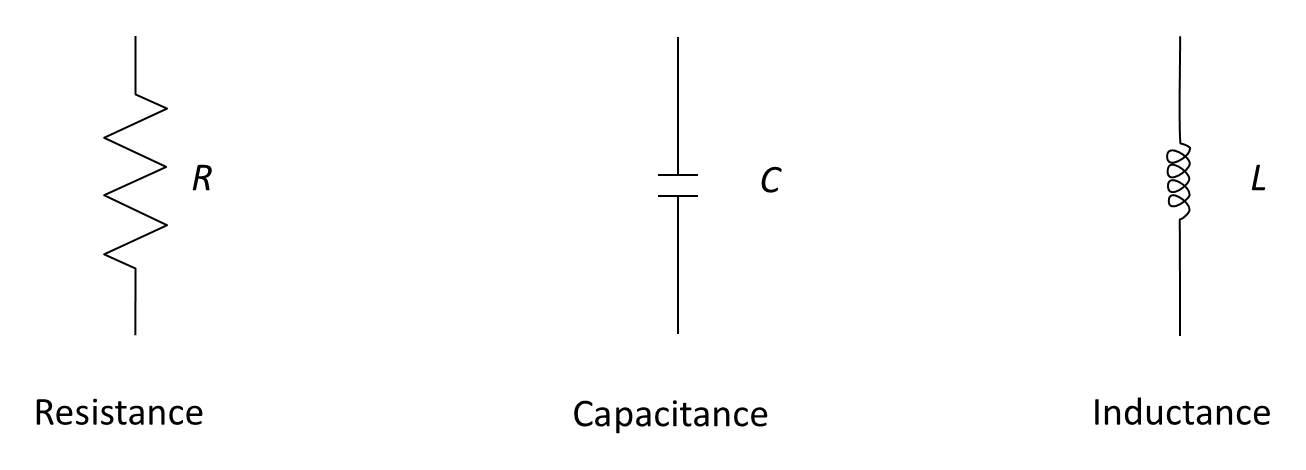
We have already met resistance as a measure of the reluctance of a material to support electron flow. All circuits have some resistance since no real components have electrons that are perfectly free to move.
The capacitor is obtained by placing two conducting plates near to each other, separated by a non-conducting material called a dielectric. The capacitance, C, of the capacitor is measured in farads (F), named after Michael Faraday. A voltage across the plates results in an electric field between them and the current that flows is directly proportional to the time rate of change of the voltage across the plates. In steady state, a capacitor therefore acts as an open circuit to DC.
A current passing through a wire produces a magnetic field around the wire. Winding the conductor into a coil strengthens the magnetic field. The resulting element is called an inductor, whose inductance (L) is measured in henry (H), named after Joseph Henry. The voltage across an inductor is directly proportional to the time rate of change of the current through it. In steady state, an inductor therefore acts as a short circuit to DC.
Impedance. In AC circuits, resistance generalizes to impedance (Z), which represents opposition to current in the presence of capacitance and inductance. Impedance depends on frequency and may include both resistive and reactive (capacitive and inductive) components. The resistive component dissipates energy and results in attenuation of signals. The reactive component stores and releases energy, introducing phase shifts that vary with frequency. When different frequency components experience unequal phase shifts or amplitudes, signal distortion can occur. In transmission media, attenuation can often be compensated by amplification, whereas distortion requires equalization or other corrective measures.
Back to reading