
Volume 18, Number 3, November 2015
An Architecture Based Approach To Assess The Reliability And Performance Of Naval Platforms
- 1 Institute for Systems Studies and Analyses, Metcalfe House, Delhi 110054, India.
- 2 Reliability Engineering Center, Indian Institute for Technology, Kharagpur, West Bengal, India.
Abstract
With rapid advances in technology, there is an ever increasing need for deploying increasingly complex defence systems to be fielded in operation within costs, time and acceptable end-use functionality. The design of such large-scale military systems are done by integrating off-the-shelf sub-systems, and component-based systems along with indigenously developed systems, ensuring interoperability, functionality and performance. As the size and complexity of systems increases, the design problem goes beyond component and subsystem design or the design of algorithms and data structures of the computation in the sub-systems. The proliferation of software systems have triggered a transition from the hardware oriented military systems to systems that are controlled by software and more so towards embedded systems. In this paper, we extend and apply a framework based reliability assessment approach for a naval system architecture based on a scenario analysis. This approach enables us to infer the system reliability from aspect reliabilities based on the composition methods, allowing the application specific aspects to be added dynamically or upgraded at a later stage. The design of a system as a framework that can support plug-in application specific aspects is an effective way of simplifying the system and assuring high quality by making the specification of each aspect as well as composition component more amenable to rigorous analysis. In order to assess the performance of these systems in various real time warfare scenarios, a Discrete Time Markov Chain is constructed. This methodology can be applied in early design stages to allow the designer to understand the effect of operational degradation factors and their effects that occur over the days of war. The methodology has been effectively applied to carry out the sensitivity analysis of the sub-systems with respect to the scenario based operations and compute mission reliability.
I. Introduction
With rapid advances in technology, there is an ever increasing need for deploying increasingly complex defence systems to be fielded in operation within costs, time and acceptable end-use functionality. The design of such large-scale military systems are done by integrating off-the-shelf sub-systems, and component-based systems engineering along with indigenously developed systems, ensuring interoperability, functionality and performance. The proliferation of software systems have triggered a transition from the hardware oriented military systems to systems that are controlled by software and more so towards embedded systems. Military systems such as naval platforms, which are naval warships configured with advanced sensors, data processing units, weapons and features like stealth, high speed, full-sensor fusion systems necessitate the usage of hardware and software based system architectures. The complexity of such systems, such as a typical naval system is very high because of factors like real time operations, interconnections of many subsystems, interdependency of various subsystems and their interfaces. Specifying the reliability and assessing the performance of the overall system of systems structure is emerging as a new kind of a problem for such complex systems.
Prevalent approaches to characterize the behaviour of monolithic applications are inappropriate to model complex real time cyber-physical systems which are heterogeneous, and are built using a combination of components picked off the shelf, those developed in-house and those developed contractually which are interwoven as a system architecture. The existing approaches to predict the reliability of systems are applicable very late in the life-cycle and ignore information about testing and reliabilities of the components of which the system is made and do not take into consideration the architecture of the system. Earlier efforts in the area of architecture-based analysis have focused on the development of composite models which are quite cumbersome due to their inherent largeness and stiffness.
In this paper a methodology has been proposed to predict the performance and reliability of component-based large scale naval systems based on their architecture. The effect of sensitivity of the performance and reliability predictions to the changes in the parameters of individual modules is considered. The performance and reliability prediction as well as sensitivity analysis techniques have been illustrated taking a case study of naval systems.
II. ARCHITECTURE BASED APPROACH TO RELIABILITY ANALYSIS
As the size and complexity of systems increases, the design problem goes beyond component and subsystem design or the design of algorithms and data structures of the computation in the sub-systems. Military architectural frameworks are powerful tools for enabling system architects to define, design, plan and implement architectures. The application of architecture based methodology at the design stage of complex, real time defence systems has been well documented [1]. An effective approach for designing systems is by application oriented frameworks where each framework has common core components that are reused over all applications in a product-line and plug-in aspects that can be added, upgraded or removed dynamically to meet the varying requirements of missions. Each plug in aspect is designed to be certifiable independently of other aspects or the framework. A framework consists of two sets of independent aspects and one composition component donated by {S, A, C}. Here S = {s1, s2, s3, s4 ……. sn} denotes the set of fixed or static framework aspects that address functional as well as non-functional requirements. Requirement imposed on these aspects is that they are independent of each other. A = { a1, a2, a3, a4 ……. an } denotes set of plug-and-play application components that can be dynamically added to or removed from the framework. These aspects implement specific features or functional aspects of the application. Component C denotes the composition component [2].
The quality Q of the aspect is the value provided to the user by correct operation of that aspect. The term quality or quality of service provided by the system is analogous to performance, composition can take several forms such as montage, selection, filter, nesting and fusion.
Montage. Here, the output of each component is evident in the final system output which forms a specified montage of the outputs of all the aspects. This composition makes the success or failure of each aspect directly visible in the final output. Reliability and quality are given as:
R(t) = { r1(t), r2(t), r3(t), r4(t) … rn(t) } – Reliability vector of Application Aspects
Q = { q1, q2, q3, q4 … qn } – Quality Vector
C(Q) – Composition Expression for System Quality
C[QR(t)] – Average Quality of the system output
QR(t) = { q1 x r1(t), q2 x r2(t), q3 x r3(t), q4 x r4(t) ... qn x rn(t) }
Selection. Here, all the aspects process the same set of inputs and the output of one of the aspects is selected to be the output of the system.
P = { p1, p2, p3, p4….. pn} – Probability vector of Application Aspects that a particular aspect is selected
Ri – Reliability of the Aspect Ai
Fusion. In this case, the composition component processes all the outputs and generates the final system output.
Nesting. This occurs in pipeline processing where an aspect has an inverse aspect, such as coder and decoder aspects, encryption and decryption routines, compression and decompression routines.
Filtering. This also occurs in pipeline processing where each aspect processes the output of the previous stage and removes or adds some information while preserving other information.
The methodology gives the system output in the form of Quality in addition to Reliability. Quality is similar to a reward function similar to performance of the system which is added provided the aspect is doing a correct operation. In case the aspect fails to perform correct operation, the Quality of the aspect will be given a value of 0. This will in turn result in the degraded performance which is reflected in the mission reliability calculation.
III. ASSESSMENT OF RELIABILITY and QUALITY FACTORS FOR NAVAL PLATFORMS
The extraordinary technological advancements taking place in satellites, sensors, communication and computers coupled with new ideas of naval tactics and force structures, would lead to one of the most sweeping revolutions in warfare. The fundamental role of the Navy is to project and safeguard the national maritime interests in the times of peace, tension and conflict. It has to protect its shores from all type of threats be it from air, from sea, land and under water.
Naval Platform implies all types of ships that are specifically designed for the use of naval forces. They differ from merchant and civilian ships in terms of design, construction and use. Navy ships are normally made of specialised steel alloy that makes them damage resilient during the enemy attacks. Most of navy ships are armed with advanced weapon system with exception of troop transporters where armament is light or non-existent. Navy ships that are exclusively built for combat are called warships.
Design of Naval Ships
In order to maintain technological superiority and dominance in the battle field, designers of the naval ships are required to be agile in adapting these “commercial-off-the-shelf” technologies and other evolving indigenous technologies for self-reliance. The present day warships are designed to engage in anti-surface, anti-air and anti-submarine warfare and carry out power projection missions. They are supplemented with air and surface surveillance radars, sonars, electronic counter measures, direction finders as well as support from fixed and rotary wing aircraft to enable complete success of an operation. Active and passive features/signatures like wake reduction, noise reduction, hull and super-structure shaping and electromagnetic and infrared emission control have been effectively overcome in the design. Higher combat speeds have been obtained to achieve tactical superiority by quick deployment and to maintain high flexibility of naval forces.
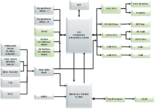
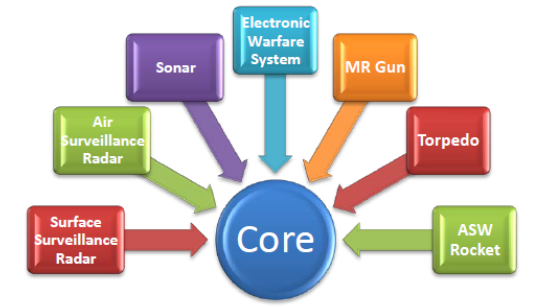
A typical naval ship consists of the various subsystems which have a lot of interdependence. These overall interconnections of the subsystems are shown in Fig. 1. Naval systems are complex, and hence it is imperative to treat them as a framework consisting of several subsystems and components: core components and certain application specific components. The core or static components will be common while the application specific components will differ depending on the role a particular ship has to perform. A naval warship whose primary role is anti-submarine warfare (to fight against underwater threats), will have application specific components like sensors and weapons pertaining to underwater attack.
These scenarios are treated as aspects. The reliability of the ship depends on the various aspects (roles) it supports and is computed using a framework based methododology.
Attack Scenarios: Aspects for Architecture Evaluation
The various attack scenarios that a warship can undergo when at sea are listed below:
Underwater Attack: This attack is carried out from underwater by an enemy submarine or a torpedo fired by an enemy ship or submarine.
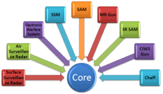
Surface Attack. This type of attack is carried out from sea by an enemy ship. The various weapons used in case of surface attack are (a) Surface to Surface Missile. The missile system is used as the first level of defence against enemy ships. (b) Medium Range Gun. The gun generally having a range of 15-20 km is used to fire against surface targets which are within the firing range. (c) Close in Weapon System Gun. A gun-based CIWS usually consists of a combination of radars, computers, and multiple-barrel rapid-fire medium-calibre guns placed on a rotating gun mount..
Air Attack. This type of attack is carried out from air by an enemy aircraft. The various weapons used in case of air attack are (a) Surface to Air Missile. The missile system is used as the first level of defence against enemy aircraft. (b) Medium Range Gun. The gun generally having a range of 15-20 km is used to fire against air targets which are within the firing range. (c) Close in Weapon System Missile. Missile systems are fired against air targets within a range of 10 km.
The way the different set of subsystems perform and interact with each other vary from one scenario to other. The interconnections between the systems on a ship are complex with several layers of interdependence. For ease of demonstration, in this paper we have considered the underwater aspect and calculate its reliability by application of architecture based framework methodology. Considering the entire system would have been a very tedious task, so in order to show the use of the methodology a particular scenario of underwater attack was considered.
Unified Modelling Language
Unified Modelling Language (UML) is used to describe the complex architectures. The interaction of the weapon and sensors was understood by drawing the Class Diagrams, Activity Diagrams and Sequence Diagrams pertaining to the underwater attack Scenarios. The functionalities pertaining to the underwater attack were considered and their interactions are brought out.
Event Flow for Firing Underwater Weapon
The ship requires information regarding its own position at sea so as to get a reference point. This information is provided by various sensors like Gyro, Global Position Indicator, Log and Wind Speed and Direction Sensor. Inputs from these sensors are termed as Ship Data Feed and are fed as reference for all other systems. Once the underwater targets are detected by the Sonar of the ship, the information is fed to the Centralised Information Centre (CIC). The CIC processes the target information by categorising into either a friend or foe. The categorised list is then displayed as picture presentation and threat evaluation for the designated targets is carried out. The targets carrying the maximum threat are considered first for neutralisation and a feed regarding it is given to the Anti-Submarine Fire Control system (ASWFCS). The above actions are common for firing any underwater weapon, the difference being in the firing data calculation of both torpedo and ASW rockets. Further actions which differ for firing of the weapon are listed below along with their complete event flow diagrams.
Categorization of Subsystems Depending on Framework-based Approach
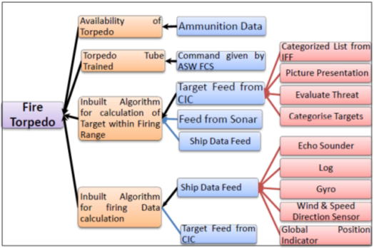
From the event flow for firing of underwater weapons (Fig. 4), certain components are common in firing of both the weapons, while certain components are specific to firing of a torpedo or ASW rockets. Based on the framework based approach, the common components are termed as core and the specific components are termed as application oriented. The categorization of the core and application specific components is as follows:
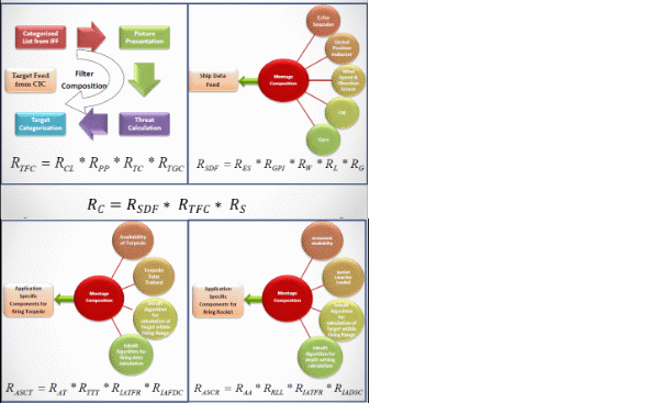
(a) Core Components. These components are common for firing both the weapon. Some core components like Gyro, Global Position Indicator, Log, Echo Sounder, Wind Speed and Direction Sensor, combine together to form the Ship Data Feed. Others such as categorized list from IFF, picture presentation, threat evaluation and Target categorization combine to form the target feed from CIC. Feed from Sonar is another component which is common to firing of both the underwater weapons. Various composition constructs to combine the components in core as well as application specific are given below:
(i) Ship Data Feed. Ship Data Feed gives a combination of information from various sensors like Gyro, Echo Sounder, Log, Global Position Indicator and Wind Speed and Direction Sensor. Since the final output of the Ship data feed contains information which is a combination of information from the above mentioned sensors, montage composition can be applied to it.
Reliability and Quality calculations are carried out as per the methodology proposed. The quality values depend on the correct operation of that component or aspect depicting the performance of the components. The systems with high performance values will be given a higher quality value. The term quality is given as the reward function which is calculated based on the composition used to combine the sub-systems.
Reliability and Quality Calculation
QSDF – Reliability and Quality of Ship Data Feed
RES and QES – Reliability and Quality of Echo Sounder
RGPI and QGPI – Reliability and Quality of Global Position Indicator
RW and QW – Reliability and Quality of Wind Speed & Direction Sensor
RL and QL – Reliability and Quality of Log
RG and QG – Reliability and Quality of Gyro
(ii) Target Feed from CIC. The target feed from CIC is obtained by processing the information from a set of sensors. Here the output of one component forms the input of the other and hence filter composition can be applied effectively here.
Reliability and Quality Calculation
RTFC and QTFC – Reliability and Quality of Target feed from CIC
RPP and QPP – Reliability and Quality of Picture Presentation
RCL and QCL – Reliability and Quality of categorised list from IFF
RTC and QTC – Reliability and Quality of Threat Calculation
RTGC and QTGC – Reliability and Quality of Target Categorisation
Reliability Calculation for Scenario
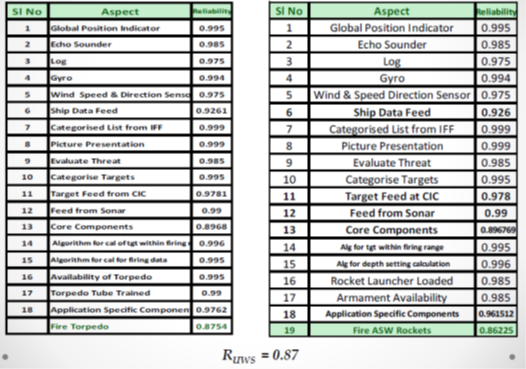
The designer, while designing the systems to face the underwater attack needs to know if the systems designed have the desired reliability. In order to assess the reliability of firing of a particular weapon, the reliabilities of the core components as well as the application specific components have to be considered. The reliability assessment for firing of the underwater weapons can be computed as:
Reliability Computation of Core Components
The reliability calculation for firing a weapon in a particular scenario is carried out by calculating the reliability of firing the weapons first and then combining them using a suitable composition construct.
(a) Reliability calculation for firing a torpedo. The reliability calculation will include the calculation of reliability for the core components and specific components pertaining to firing of a torpedo.
Reliability of Torpedo firing – Reliability of Core components × Reliability of Application specific components
RTF – RC × RASCT
RTF – Reliability of Torpedo Firing
RASCT – Reliability of Application specific components
Reliability of Application Specific components –
Reliability of torpedo firing
where:
Rc – Reliability of core components
RSDF – Reliability of Ship Data Feed
RTFC – Reliability of Target feed from CIC
Rs – Reliability of Sonar
RASC and QASC – Reliability and Quality of Application Specific components
RASC and QASC – Reliability and Quality of Application Specific components
RAT and QAT – Reliability and Quality of Availability of Torpedo
RTTT and QTTT – Reliability and Quality of Torpedo Tube Trained
RIAFDC and QIAFDC – Reliability and Quality of Input Algorithm for calculation of target within firing range
RIAFTR and QIAFTR – Reliability and Quality of Input Algorithm for firing data to Torpedo
(b) Reliability calculation for firing ASW rocket. The reliability calculation will include the calculation of reliability for the core components and specific components pertaining to firing of an ASW rocket.
Reliability of ASW Rocket firing – Reliability of Core components × Reliability of Application specific components
RRF – RC × RASCR
RRF – Reliability of Rocket Firing
RASCR – Reliability of Application specific components for firing Rocket
Reliability of Application Specific components –
In case of an underwater attack, either a torpedo or an ASW rocket can be fired, so there can be a selection composition between the application specific components for firing a torpedo or firing ASW rocket, while the core components will remain the same. In order to calculate the reliability for underwater scenario:
The proposed methodology can be effectively used to carry out a what-if analysis for reliability apportionment. In case the reliability goal of the system is known, the framework based methodology can be applied to know the required reliability of the various sub-systems. Most of the sub-systems nowadays are available as commercially off the shelf, knowing the reliability of the sub-systems will allow the designer to pick the sub-systems suited for achieving the end goal scenario reliability. In case the scenario or system reliability is not known, the methodology helps the designer to pick from the available sub-systems and calculate the maximum scenario reliability.
The methodology allows the architecture of the systems to be built which can be used across different class of ships. A particular class of ship which is designed to carry out underwater operations should have the application specific components with high reliability values pertaining to underwater attack but may contain application specific components pertaining to air attack with moderate reliability values. Such calculations at the design stage will allow the designer to have the knowledge of the required sub-systems and help the designer to design complex systems faster having a better quality. Once the systems are designed, there ought to be a method to check the performance of the systems in real time situations and the effect of the degradation on its performance. The next section deals with the methodology to carry out such an analysis.
Application of DTMC for Performance Evaluation
Discrete Time Markov Chains (DTMCs) have been applied to a variety of practical problems in real-world domains. The real world systems degrade when used continuously over a period of time, markov chains can be used to estimate performance or reliability as a consequence of constant use of the complex systems.
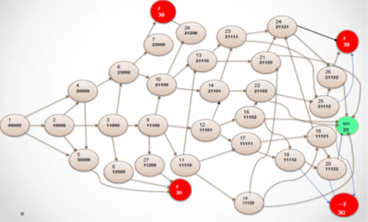
The naval systems after being developed and functional, there is a requirement to assess the reliability and performance of the warship in particular attack scenario before the systems are actually fitted onboard a naval platform. As the naval ship has to be at sea for long duration and can be engaged with enemy repeatedly during this period. The effectiveness and reliability of the sensors and weapon systems are key to its success during the entire period. In addition knowing the degradation pattern or mission success or failure probability will aid naval, operational planning, resource allocation and naval war gaming. The performance of systems’ will not behave the same way throughout the period of their engagement (or days of progress of war) due to failures, people morale, operator fatigue, and operational Degradation which may cause the performance of the systems to fall. Taking the case of underwater scenario, the entire process of firing a weapon on a target detected by a Sonar, the system translates from one state to the other till it reaches the Mission Complete State or the Failed state. Discrete Time Markov Chains (DTMC) permit to model the transition probabilities between discrete states by the aid of matrices. The various states of the system are shown in Table 2.
| State | Sonar(a) | CIC(b)/ ASWFCS(c) | Torpedo(d)/ Rocket(e) |
|---|---|---|---|
| 0 | Idle. No Transmission | Idle. No Data Processing | Idle. Firing Data not Fed. |
| 1 | Functional | Functional | Firing Data Fed |
| 2 | Degraded Functional | Failed | Fired |
| 3 | Failed | ------ | ----- |
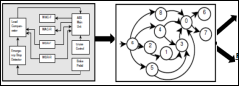
By the use of Control flow graph, the various possible states of the system are addressed and the transition probabilities for moving from one state to another can be listed.
After the control flow graph for the states is constructed, the transition probabilities are assigned. The various values of the state transition matrix are used to classify the effect of degradation on the system effectiveness in a particular scenario. These values were obtained from the simulation software called war-gaming which represents the real time scenario. The state diagram can be used to understand the usage profile of the system which will depend on the operational degradation with respect to time and the sensitivity analysis with respect to the various subsystems.
Usage Profile
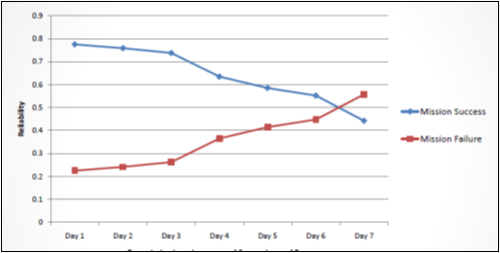
The naval systems, when operational during naval exercises or during war are subject to operational degradation. There is a need to understand the effect this degradation will have on the success of the mission or failure. The transition matrices for various levels of degradation levels were formulated and the various transition probability values were utilised in the R Cran software to calculate the steady state values of the two absorbing states that are Mission success and mission failure.
The graph shows how the degradation as a result of the ODF depending on the usage profile of the system affects the mission completion and failure reliabilities for the underwater attack scenario. It can be seen that the system performance and hence mission reliability degrades with the increased usage in operational scenarios. There is always a desired reliability level allocated to mission success and it is required that the mission success reliability does not fall below the acceptable limits. Application of DTMC at the design stages allows the designer to check if the systems designed are meeting the mission requirements even in the adverse war scenarios.
Sensitivity Analysis
Application of DTMC to the naval systems helped to analyse how sensitive is a particular sub-system for the overall system performance and reliability. With the criticality of the sub-system known, emphasis can be put more on that particular system to make it more rugged. To carry out this, the transition probabilities of one particular subsystem is changed and then the effect on the system is observed in terms of the mission completion reliability and mission failure reliability.
The figure shows the effect of same levels of degradation on different components like Sonar and ASWFCS and its effect on the overall performance of the system which is given as Mission Success and Mission Failure reliabilities. The sensitivity analysis allows the designer to see the effect of degradation pattern of the sub-systems on the overall system performance and single out the most critical components which have direct effect on the mission success reliability. The critical/most sensitive sub-systems can be redesigned or any other suitable measure can be taken at the design stage itself.
IV. Conclusions and Discussion
In this paper, we explored the techniques for reliability and performance based design of architectures for military systems. Prevalent approaches to characterize the behaviour of monolithic applications are inappropriate to model complex real time systems which are heterogeneous, and are built using a combination of components picked off the shelf, those developed in-house and those developed contractually which are interwoven as architecture. These approaches to predict the reliability of systems are applicable very late in the life-cycle and ignore information about testing and reliabilities of the components of which the system is made, and do not take into consideration the architecture of the system. Development of techniques to characterize the behaviour of such component-based systems based on their architecture is then absolutely essential. Earlier efforts in the area of architecture-based analysis have focused on the development of composite models which are quite cumbersome due to their inherent largeness and stiffness. A methodology has been proposed to predict the performance and reliability of component-based large scale naval systems based on their architecture. The effect of sensitivity of the performance and reliability predictions to the changes in the parameters of individual modules is considered. The performance and reliability prediction as well as sensitivity analysis techniques have been illustrated taking a case study of naval systems.
In the proposed methodology, a framework based reliability assessment approach for decomposing and implementing a naval system based on a particular scenario is presented and evaluation of the same in form of architectures carried out. The main constructs for evaluating the reliability of architectures represented by unified modelling language are montage, filtering, selection and fusion. Using these constructs, the architecture based reliability models are assessed and this methodology is illustrated using a naval platform system as a case study. The approach enables the system reliability to be rigorously inferred from aspect reliabilities based on the composition methods, allowing the application specific aspects to be added dynamically or upgraded at a later stage. The design of a system as a framework that can support plug-in application specific aspects is an effective way of simplifying the system and assuring high quality by making the specification of each aspect as well as composition component more amenable to rigorous analysis. It helps the designer to carry out reliability apportionment if the desired reliability for the mission is not met at the design stage itself. The methodology also helps in defining the reliability goals for the system designer.
In order to assess the performability of these systems in various real time scenarios, a Discrete Time Markov Chain is constructed. This methodology can be applied in early design stages to allow the designer to understand the effect of operational degradation factors due to the usage profile of the entire system in a particular scenario during actual usage. Such a scenario based operational analysis can be carried out keeping the reliability constraints of the sub-systems in mind by the application of Markov chain. The methodology can be effectively applied to carry out the sensitivity analysis of the sub-systems with respect to the scenario based operation. The criticality of a particular subsystem in respect to the system functioning goes a long way in giving the designer an insight into how effective the system has been designed. This also helps the designer to identify the weak subsystems, wherein measures can be taken to improve the reliability of the sub-system at the design stage itself. The methodology proposed can be effectively used to carry out the what-if reliability and performance analysis and aid in apportionment for the subsystems.
(b) The study carried out takes in to consideration the reliability and performance of the system for carrying out the architecture based evaluation. Some of the other criteria which can be explored are safety, availability, maintainability and sustainability.
(c) The study presents one of the possible techniques for modelling of architecture based systems for calculation of reliability and performance of the system. Other possible techniques for such evaluations can be explored and their applications for architecture based assessment can be evaluated.
(d) Another notable feature for which the study can be utilised is the application of modelling and simulation techniques for reliability and performance evaluation based acquisition.
Appendix A
Description of various states of the DTMC
| State No | State abcde | Description of the State |
|---|---|---|
| 1 | 00000 | Sonar, CIC, ASWFCS, Torpedo and ASW Rocket in Idle State. |
| 2 | 10000 | Sonar in Functional State ie Sonar is transmitting and detecting all available targets. |
| 3 | 11000 | Sonar in Functional State. On detection of Target, the target details are sent to CIC and CIC comes to Functional state. |
| 4 | 20000 | Sonar in degraded state, the Sonar will not be able to track all the targets completely. |
| 5 | 30000 | Sonar is in failed state. It is not able to transmit. |
| 6 | 21000 | Sonar in Degraded state. On detection of Target, the target details are sent to CIC and CIC comes to Functional state. |
| 7 | 22000 | Sonar is in Degraded State. The target is detected but on receiving the target details, the CIC goes to failed state. |
| 8 | 12000 | Sonar in Functional State. On detection of target, the details are sent to the CIC but CIC goes to failed state and is unable to process the targets. |
| 9 | 11100 | Sonar in Functional State. On detection of targets, details are sent to CIC which is in functional state and starts processing the targets and sends the data to the ASWFCS which comes to Functional state and does the Firing data calculation. |
| 10 | 21100 | Sonar is in degraded state. The detected target details are sent to CIC which is in functional state and starts processing the targets and sends the data to the ASWFCS which comes to Functional state and does the Firing data calculation. |
| 11 | 11110 | Sonar in Functional State. On detection of targets, details are sent to CIC which is in functional state and starts processing the targets and sends the data to the ASWFCS which comes to Functional state and does the Firing data calculation. After processing by ASWFCS, the weapon selected is Torpedo and firing data is fed to it. |
| 12 | 11101 | Sonar in Functional State. On detection of targets, details are sent to CIC which is in functional state and starts processing the targets and sends the data to the ASWFCS which comes to Functional state and does the Firing data calculation. After processing by ASWFCS, the weapon selected is ASW Rocket and firing data is fed to it. |
| 13 | 21110 | Sonar is in degraded state. The detected target details are sent to CIC which is in functional state and starts processing the targets and sends the data to the ASWFCS which comes to Functional state and does the Firing data calculation. After processing by ASWFCS, the weapon selected is Torpedo and firing data is fed to it. |
| 14 | 21101 | Sonar is in degraded state. The detected target details are sent to CIC which is in functional state and starts processing the targets and sends the data to the ASWFCS which comes to Functional state and does the Firing data calculation. After processing by ASWFCS, the weapon selected is ASW Rocket and firing data is fed to it. |
| State No | State abcde | Description of the State |
| 15 | 11120 | Sonar in Functional State. On detection of targets, details are sent to CIC which is in functional state and starts processing the targets and sends the data to the ASWFCS which comes to Functional state and does the Firing data calculation. After processing by ASWFCS, the weapon selected is Torpedo, firing data is fed to it and Torpedo is fired. |
| 16 | 11102 | Sonar in Functional State. On detection of targets, details are sent to CIC which is in functional state and starts processing the targets and sends the data to the ASWFCS which comes to Functional state and does the Firing data calculation. After processing by ASWFCS, the weapon selected is ASW Rocket, firing data is fed to it and ASW Rocket is fired. |
| 17 | 11111 | Sonar in Functional State. On detection of targets, details are sent to CIC which is in functional state and starts processing the targets and sends the data to the ASWFCS which comes to Functional state and does the Firing data calculation. After processing by ASWFCS, the firing data is fed to ASW rockets and Torpedo. |
| 18 | 11121 | Sonar in Functional State. On detection of targets, details are sent to CIC which is in functional state and starts processing the targets and sends the data to the ASWFCS which comes to Functional state and does the Firing data calculation. After processing by ASWFCS, the firing data is fed to both the weapons and torpedo is fired. |
| 19 | 11112 | Sonar in Functional State. On detection of targets, details are sent to CIC which is in functional state and starts processing the targets and sends the data to the ASWFCS which comes to Functional state and does the Firing data calculation. After processing by ASWFCS, the firing data is fed to both the weapons and ASW rocket is fired. |
| 20 | 11122 | Sonar in Functional State. On detection of targets, details are sent to CIC which is in functional state and starts processing the targets and sends the data to the ASWFCS which comes to Functional state and does the Firing data calculation. After processing by ASWFCS, the firing data is fed to both the weapons and both the weapons are fired. |
| 21 | 21120 | Sonar in degraded state. On detection of targets, details are sent to CIC which is in functional state and starts processing the targets and sends the data to the ASWFCS which comes to Functional state and does the Firing data calculation. After processing by ASWFCS, the weapon selected is Torpedo, firing data is fed to it and Torpedo is fired. |
| 22 | 21102 | Sonar in degraded state. On detection of targets, details are sent to CIC which is in functional state and starts processing the targets and sends the data to the ASWFCS which comes to Functional state and does the Firing data calculation. After processing by ASWFCS, the weapon selected is ASW Rocket, firing data is fed to it and ASW Rocket is fired. |
| 23 | 21111 | Sonar in degraded state. On detection of targets, details are sent to CIC which is in functional state and starts processing the targets and sends the data to the ASWFCS which comes to Functional state and does the Firing data calculation. After processing by ASWFCS, the firing data is fed to the weapons. |
| State No | State | Description of the State |
| 24 | 21121 | Sonar in degraded state. On detection of targets, details are sent to CIC which is in functional state and starts processing the targets and sends the data to the ASWFCS which comes to Functional state and does the Firing data calculation. After processing by ASWFCS, the firing data is fed to both the weapons and torpedo is fired. |
| 25 | 21112 | Sonar in degraded state. On detection of targets, details are sent to CIC which is in functional state and starts processing the targets and sends the data to the ASWFCS which comes to Functional state and does the Firing data calculation. After processing by ASWFCS, the firing data is fed to both the weapons and ASW rocket is fired. |
| 26 | 21122 | Sonar in degraded state. On detection of targets, details are sent to CIC which is in functional state and starts processing the targets and sends the data to the ASWFCS which comes to Functional state and does the Firing data calculation. After processing by ASWFCS, the firing data is fed to both the weapons and both the weapons are fired. |
| 27 | 11200 | Sonar in Functional State. On detection of targets, details are sent to CIC which is in functional state and starts processing the targets and sends the data to the ASWFCS. The ASWFCS being in failed state, no firing data calculation is done and weapon cannot be fired on the target. |
| 28 | 21200 | Sonar in degraded state. On detection of targets, details are sent to CIC which is in functional state and starts processing the targets and sends the data to the ASWFCS. The ASWFCS being in failed state, no firing data calculation is done and weapon cannot be fired on the target. |
| 29 | MC | Mission Complete. Target is destroyed. |
| 30 | MF | Mission Fail. Target is not destroyed. |
References
[1] F. Bastani, S. Kim, “Systematic Reliability Analysis of a Class of Application-Specific Embedded Software Frameworks”, IEEE transactions on Software Engineering, Vol. 30, No. 4, April 2004.
[2] J. Voas, A. Ghosh, G. McGraw, and K. Miller. “Glueing together software components: How good is your glue?”, Proc. of Pacific Northwest Software Quality Conference, Portland, OR, October 1996.
[3] S.S. Gokhale, K.S. Trivedi, “Reliability Prediction and Sensitivity Analysis Based on Software Architecture”, Proceedings of the 13th International Symposium on Software Reliability Engineering (ISSRE’02), 2002. Fundamentals of Naval Weapon Systems, Weapons and System Engg Department, United States Naval Academy.
[4] F. Bastani, S. Kim, “Reliability Assessment of Framework-Based Distributed Embedded Software Systems”, Proceedings of the 13th International Symposium on Software Reliability Engineering (ISSRE’02), 2002.
[5] B. Littlewood, "Theories of software reliability: How good are they and how can they be improved?" IEEE Transactions on Software Eng., vol.SE-6, pp. 489-500, 1980.
[6] J. Voas, A. Ghosh, G. McGraw, and K. Miller. “Glueing together software components: How good is your glue?”, Proc. of Pacific Northwest Software Quality Conference, Portland, OR, October 1996.
[7] S. Gokhale, P. Kishor, “Reliability Prediction and Sensitivity Analysis Based on Software Architecture of CSE CACC”, Proceedings of the 13th International Symposium on Software Reliability Engineering (ISSRE’02), 2002.
[8] Katerina Goeva P., Kishore Trivedi, “Architecture Based Software Reliability”, Department of Electrical & Computer Engineering, Duke University, (IPDS'98), 13-22, 1998.
[9] S Gokhale, K. Trivedi, “Structure based software reliability prediction”, Proc 5th International Conference in Advanced Computing (ADCOMP 97), 447-452, 1997.
[10] B. Littlewood, “Software reliability model for modular program structure”, IEEE Transactions on Reliability, 28 (3), 241-246 (1979).
[11] R.C. Cheung, “A user oriented software reliability model”, IEEE Transactions on Software Engineering, 6 (2), 118-125 (1980).
[12] J.C. Laprie, “Dependability evaluation of software systems in operation”, IEEE Transactions on Software Engineering, 10(6), 701-714, (1984).
[13] P. Kubat, “Assessing reliability of modular software”, Operation Research Letters, 8 35- 41, (1989).
[14] S. Gokhale, W.E. Wong, K. Trivedi, J.R. Horgan, “An analytical approach to architecture based software reliability prediction”, Proc. 3rd International Computer Performance & Dependability Symposium, (IPDS 98), 13-22, 1998.
[15] S.M. Yacoub, B. Cukic, H.H. Ammar, “Scenario based reliability analysis of component based software”, Proc. 10th International Symp. on Software Reliability Engineering, ISSRE- 99, 22-31, 1999.
[16] F. Bastani, S. Kim, “Systematic Reliability Analysis of a Class ofApplication-Specific Embedded Software Frameworks”, IEEE Transactions on Software Engineering, Vol. 30, No. 4, April 2004.
[17] C. Hofmeister, R.L. Nord, D. Soni, “Describing Software Architecture with UML”, Proceedings of the First Working IFIP Conference on Software Architecture, 1999.
[18] C. Dabrowski, F. Hunt, “Using Markov chain and graph theory concepts to analyze behavior in complex distributed systems”, US National Institute of Standards & Technology, 2003.
[19] M. Karri, An architecture based approach to assess the reliability and performance of naval platforms, Masters Thesis, Indian Institute of Technology, Kharagpur, 2015.