
Volume 18, Number 3, November 2015
Enhancing Battlefield Communications Through 4G LTE+ Cellular Technology
- 1 Royal Australian Corps of Signals.
Abstract
The battlespace is a complex environment comprising of multiple domains, maritime, air, land and cyber, across a diverse range of scenarios. These scenarios span conventional warfighting to humanitarian assistance, requiring complex processes and systems and demand the enabling of increasingly technologically advanced platforms. To generate a battlespace effect information must traverse efficiently and effectively linking these diverse platforms spread between domains and across the breadth of scenarios. Currently, within the land domain this information is pushed by the Enhanced Position Location Reporting System (EPLRS) data network. However, this network will be challenged to meet emerging platforms, requirements which demand big data such as the: Joint Strike Fighter, next generation Unmanned Aerial Vehicles, P8, and increasingly complex processes such as deliberate and dynamic targeting using Full Motion Video. To enable complex processes and emerging platforms a scalable and flexible data network is required providing beyond line-of-sight, single hop connectivity to enable time critical applications and high bandwidth, big data. This paper proposes that a cellular, Fourth Generation (4G) Long Term Evolution Advanced (LTE+) architecture can meet these demands now and into the future providing a revolutionary military communications capability to the Australian Defence Force, specifically the Army.
Introduction
The current data communciations architecture supporting the Army employs legacy equipment that has been unable to keep pace with technological change and will struggle to meet the demands of future conflicts. Throughout history warfare has been a complex task and it is expected the future of warfare will continue to be driven by a broad spectrum of conflict. This spectrum ranges from high intensity conventional warfighting, to counterinsurgency (COIN) and support to the civil community through Humanitarian Aid and Disaster Relief (HADR). To enable Australian Defence Force (ADF) operations a stable, flexible, survivable communications network that provides a range of services, including: support to Command and Control (C2), provision of a Common Operating Picture (COP) and Intelligence, Surveillance and Reconnaisance (ISR) is pivotal. This network must achieve the challenge of enabling mobility whilst providing a high capacity backbone facilitating information flows from the strategic to operational and tactical environment.
This paper outlines a cellular Fourth Generation (4G) Long Term Evolution Advanced (LTE+) data architecture for the Australian Army that is affordable, effective, agile, usable and interoperable fusing high capacity tactical, operational and strategic data across the spectrum of conflict. The cellular solution is designed to replace the current and future EPLRS tactical data system. It will not replace the current CNR voice system; rather, it will overlay the C2 voice architecture. The solution decreases the weight and size of equipment carried by soldiers, enables operational manoeuvre across a fluid battlefield and results in a converged ‘single logical network’ that minimises artificial boundaries [1]. This paper builds through seven sections. A brief operational context is provided to baseline the challenge and the current EPLRS solution is then outlined. Cellular technology is then discussed, and the proposed cellular architecture within a Division, specifically a Brigade. The challenges, opportunities and security architecture design of the 4G LTE+ architecture are then outlined. The paper will conclude that a cellular architecture is an effective and efficient option to provide time critical data within the Army now and into the future.
ENABLING THE WARFIGHTER: AN OPERATIONAL CONTEXT
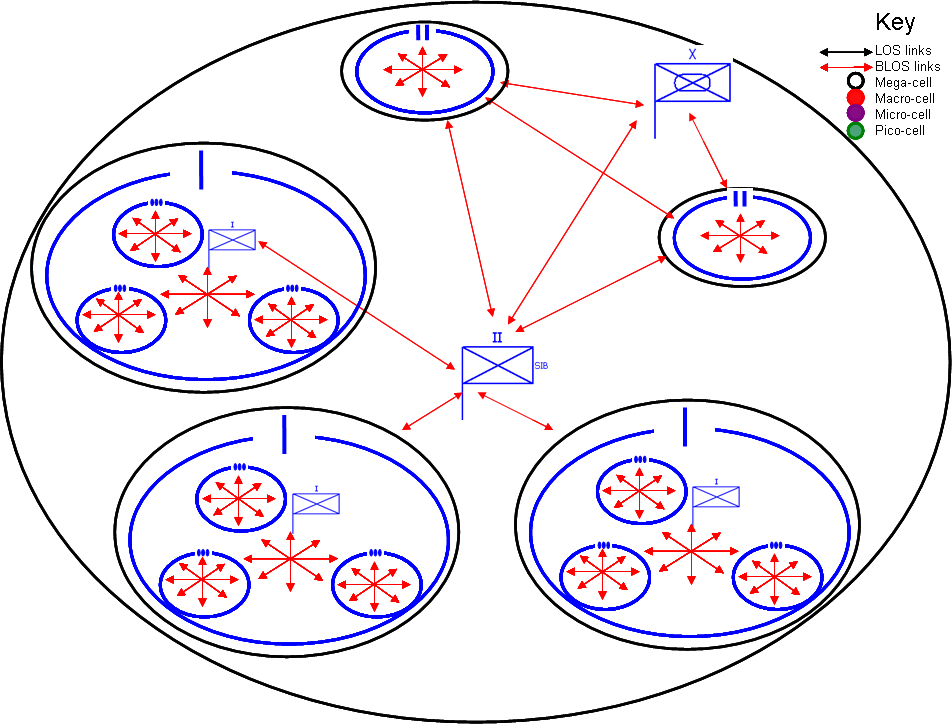
The Australian Army is a small force required to operate across the spectrum of conflict as an isolated force, a joint force (Army, Air Force and Navy), a member of a coalition (as a lead nation or troop contributing organisation) and a component of a multi-agency operation. Specifically, the Army is prescribed to provide combined arms teams in the littoral environment to secure offshore territories, defeat incursions and provide/deny access to staging bases; this requires amphibious manoeuvre, stabilisation and reconstruction operations within the region and the capability to deploy globally as a coalition member [2]. These tasks are developed across two broad environments, a concentrated (Figure 1) and a dispersed scenario (Figure 2) in an austere setting. Austere implies that the Army will “deploy to a remote location and support itself [personnel and logistics] in a hostile environment’ [3]. Further to this, the ADF’s small size demands that the same communications capability can meet the spectrum of tasks [4]. Each environment demands a flexible architecture that integrates line-of-sight (LOS) and beyond-line-of-sight (BLOS) communications to meet the range of tasks and scenarios.
Broadly this paper seeks to address seven key goals:
- Provide an expeditionary communications capability that can operate in an austere environment.
- Provide time critical high capacity information to the commander, from the Section to the Divisional HQ.
- Provide a communications architecture that is interoperable within the Army, between services (joint), is multi-agency and multi-national.
- Provide a communications capability, including baseline applications, that can be employed across the spectrum of conflict.
- Provide agile communications system that are scalable, survivable (multi-path) and secure.
- Deliver on time and schedule, with the technology remaining relevant through its life of type.
- Provide a system thats usability is largely intuitive.
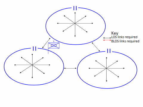
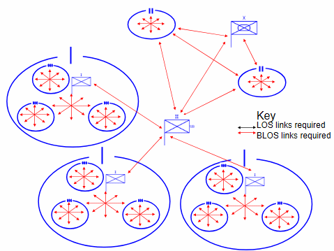
Underpinning these seven goals are the critical Information Exchange Requirements (IERs). The IERs directly enabled are: C2, secure voice (including time sensitive VoIP), secure data, secure streaming video (including FMV), deliberate and dynamic targeting, logistics requests (the central server is located in Australia), individual location reporting, fused COP and Battlefield Damage Assessment (BDA). This list is not exhaustive; however, it places a broad range of network pressures from bandwidth intensive requirements to applications influenced by latency. The solution must meet diverse tasks, in an austere environment.
THE CURRENT SOLUTION: A CNR CENTRIC APPROACH
The Army meets the data challenge through two disparate systems, the Land Tactical Network (LTN) and the Battlefield Telecommunications Network (BTN). The LTN provides on the move tactical Brigade communications in an austere environment, a traditional CNR construct [5]. The BTN provides a high-capacity trunking system, at Brigade HQ and higher [6]. Historically, the LTN solution has served the Army effectively, particularly for C2 voice. This solution does highlight a tradeoff between range, capacity and mobility; VHF provides high mobility but limited range, HF provides larger range but lower capacity and mobility [7]. Further to this, the current architecture defines the crossover point of high capacity data at the Brigade and higher level. Current technology can revolutionise this approach and provide a single logical network, where the crossover of high capacity data is removed and in turn the LTN and BTN nexus.
The traditional CNR solution has led to an optimised voice solution and a sub-optimal data architecture. The current data solution, EPLRS, is not enabled for BLOS operations, requiring battlefield LOS saturation to achieve its BLOS concept, this limits bandwidth and range. To achieve battlefield saturation the EPLRS design focuses on either a limited scope and size to maximise frequency reuse through segmenting communities and possibility isolating information [8]; or, a single community to increase collaboration, that can result in frequency reuse not being optimised and a complicated repeating architecture (every EPLRS radio becomes a Brigade asset)[9]. Importantly the EPLRS radio is not BLOS and can not provide a BLOS capability between two radios. This is not an effective solution in a dispersed operational scenario.
The current CNR paradigm employs legacy equipment; whereby, a like-for-like, linear replacement is being pursued limiting the enabling of emerging platforms. Emerging capabilities will include: multi-purpose and unmanned platforms, lethal microbots and ‘dial-a-yield’ munitions demanding integrated high capacity communications architectures [10]. Specifically, projects including: tactical UAVs, the P8 Poseidon and Joint Strike Fighter aircraft will overwhelm current networks. [11]. This challenge will not be solved through incremental change, rather a revolutionary option should be investigated to meet government ambition for Defence to ‘modernise its communications, networking and BMS’ [12]. Cellular technology provides an opportunity to develop a revolutionary military capability.
Projecting future requirements is a daunting task; however, the Army is aware that the current bandwidth demands exceed the current and planned data communications architectures. Broadly speaking there are three approaches to rectify this capability gap: (i) procure new hardware or products that do not link with any other current capability, (ii) upgrade an existing capability, or (iii) expand, complement or add to existing capabilities [13]. This paper will employ option three with the continuation of Harris radios (or equivalent) for C2 voice; however, replace the current data system, EPLRS, with a cellular solution.
DESIGNING A CELLULAR NETWORK
Cellular communications is a key technology that has advanced rapaidly and is employed globally. 4G cellular technology provides broad bandwidth and high data rates (practical tests have yielded 100 Mbps downlink and 50 Mbps uplink), efficient handovers providing better quality of service (QoS), wide coverage for enhanced mobility and cost effectiveness [14]. The next generation architecture, 4G LTE and 4G LTE+ provide higher bandwidth and when combined with Worldwide Interoperability for Microwave Access (WIMAX) will increase speeds in excess of 40 Mbps out to 30 miles [15]. However, it is the concept of integration that sets aside 4G, whereby a personal user can access a range of networks, a converged capability. The Army has a similar convergence challenge with the range of systems and applications available on the battlefield.
Whilst convergence is important, network adaptability is equally demanded. 4G technology provides this through internal diversity, the ability to transfer data between networks that employ multiple standards and protocols, and external diversity, through understanding the situations and backgrounds of people using the technology [16]. The employment of smartphone technology within Australia is widespread and Army personnel would be well versed in its daily use, compared to EPLRS radios [17]. Smartphones will also enable application adaptability whereby services can be delivered automatically according to Commanders preferences to meet differing mission sets [18]. 4G provides adaptability through its design focus on applications, rather than physical hardware, and high capacity bandwidth to support a range of IERs.
The 4G LTE+ cell design requires consideration of coverage, bandwidth and transit speed influencing cell handovers. Geographic coverage can be maximised through macro-cells; however, bandwidth is lower. Conversely, micro-cells are constrained to a smaller area, yet provide greater bandwidth. A pico-cell is limited to several metres, a nano-cell is smaller coverage again, femto-cells are small cells that mimic base stations [19]. This is a similar tradeoff to VHF and HF CNR; however, the bandwidth is significantly higher for cell networks. The key relationship remains that as coverage decreases bandwidth increases; thus, the number of cells and cell radius size will influence the bandwidth available, outlined by Figure 3. To maximise coverage an ‘umbrella design’ [20] will be employed, where by micro, pico, femto and nano-cells are overlaid with a macro or mega-cell.
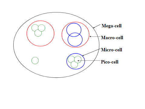
Whilst cell sizes are key to battlefield coverage, the access technique adopted will similarly influence cell efficiency. There are a range of options that the Army could adopt for cellular access methods to enhance the basic cell structure.
- Option One: Singlehop Cellular Network (SCN). SCN directly communicates via a single hop between the mobile and base station [21]. These architectures have reliable performance and mature technology; however, are costly to build, network expansion is difficult, system capacity is limited due to channel data rates and peak traffic can result in hot spots [22]. This solution requires a dense backbone to be deployed, not dissimilar to the current EPLRS solution, and thus is not recommended.
- Option Two: Multihop Adhoc Network (MANET). This architecture is comprised ‘solely of mobile users, every node (for example laptops and mobile phones) can play the role of an intermediary station that relays packets towards their destinations that otherwise cannot be reached using a single hop’ [23]. MANETs can be developed with smartphones acting as repeaters and this functionality provides an alternate path if fixed infrastructure is destroyed [24]. A MANET is relatively cheap to deploy as it is infrastructure less, is self-organising with handsets acting as repeaters, employs the IEEE802.11 spectrum, facilitates users moving fast within the battlefield, maximises bandwidth through pico style theory, and maintains connections relative to other users [25]. However, the use of this spectrum is less reliable than option one, it is difficult to control a centralised trust architecture, interference is more prevalent and multi-hop paths difficult to predict [26]. These limitations result in greater vulnerability to a mobile network. MANET is a viable option into an austere setting.
- Option Three: Multi-hop Cellular Networks (MCN). MCN employs single and multi-hop characteristics to achieve connectivity. When a mobile can reach the destination directly it employs single hop; similarly, multi-hop characteristics are employed when stations require an intermediary [27]. MCN employs an umbrella style solution to the cell structure with pico and micro-cells overlaid with macro and mega-cells to achieve single hop connectivity. MCN can reduce transmit power by using multiple hops to closer stations, increase system capacity through frequency reuse, provide higher data rate services when employing IEEE802.11, balance traffic and improve reliability through intelligent routing [28]. The system does however have a high level of complexity with respect to handover and routing, potentially weak security and possible delay if packets are buffered [29]. Whilst security is a concern, this challenge can be mitigated through a secure connection within a Virtual Private Network (VPN), discussed in latter sections. When employing VPNs and deploying an umbrella style cell structure MCN is a viable option that embodies the strengths of SCN and MANET. This is the recommended cellular network design within the Brigade.
- Option Four: Small Cell Networks (SCN). SCNs are based on the ‘very dense deployment of self-organising low-cost, low-power, base stations’, this increases system capacity, through small cell sizes provided by pico, femto and/or nano-cells [30]. To provide this cluster service a density needs to be achieved. This is a viable solution within a small geographic area, such as a Brigade HQ, BMA, or during concentrated Brigade operations.
This paper will employ an MCN structure in the Brigade and SCN within the BMA and Brigade HQ.
A PROPOSED SOLUTION: 4G LTE+ CELLULAR NETWORK
The proposed 4G LTE+ solution establishes high capacity islands (clusters), linked by repeaters and traditional military trunking, HCLOS radios and SATCOM. The solution leverages commercial off the shelf (COTS) systems developed and employed during Phase Zero operations for immediate deployment in Phase One of a Contingency Operation [31]. This network comprises high capacity femto, pico, micro and macro-cells, which provide high bandwidth islands to enable the employment of a highly capable end user device (EUD) within a Closed Subscriber Group (CSG). Coordinated multipoint (CoMP) will be employed to allow base stations to form a single cell facilitating a handset to connect to several base stations at the same time. Importantly, this can also increase network survivability as ‘neighbouring base stations can send the same data to the device simultaneously’ [32]. The EUD will directly connect into these high capacity islands and converge applications onto one platform, a smartphone [33]. These high capacity islands are then replicated across the battlefield and connected via a high capacity backbone. The 4G LTE+ architecture provides direct connections to high bandwidth platforms and access to real time services such as FMV.
The cell architecture will naturally create high capacity battlefield clusters. However, these clusters require a high capacity backbone. The following backbone options are presented, illustrated at Figure 4:
- HCLOS. LOS connections will be provided by HCLOS capabilities mounted on a Protected Mobility Vehicle (PMV) or trailer, organic to the unit. The second capability is a pool of air transportable HCLOS towers that can be inserted on the battlefield by air (helicopter lift) or road. These towers will not have classified equipment and can be destroyed in place if required.
- TDMA SATCOM. TDMA SATCOM is the core element of the backbone architecture and will be required to be transportable in the dismounted and mounted role. The dismounted role employs micro VSAT, where appropriate, with VSAT employed on mounted platforms.
- FDMA SATCOM. FDMA satellite terminals, 2.4 metres or greater, will be provided to the Brigade to connect to high capacity dedicated nodes (internal), the Division or the strategic environment.
- Airbone repeaters. Helicopters and UAVs can be enabled with airborne repeaters in a low threat environment.
- Mega-cells. These cells provide a broad geographic coverage supporting single hop connectivity.
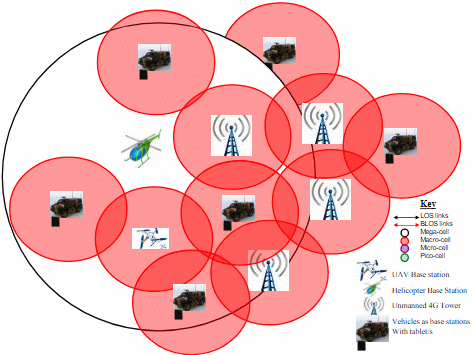
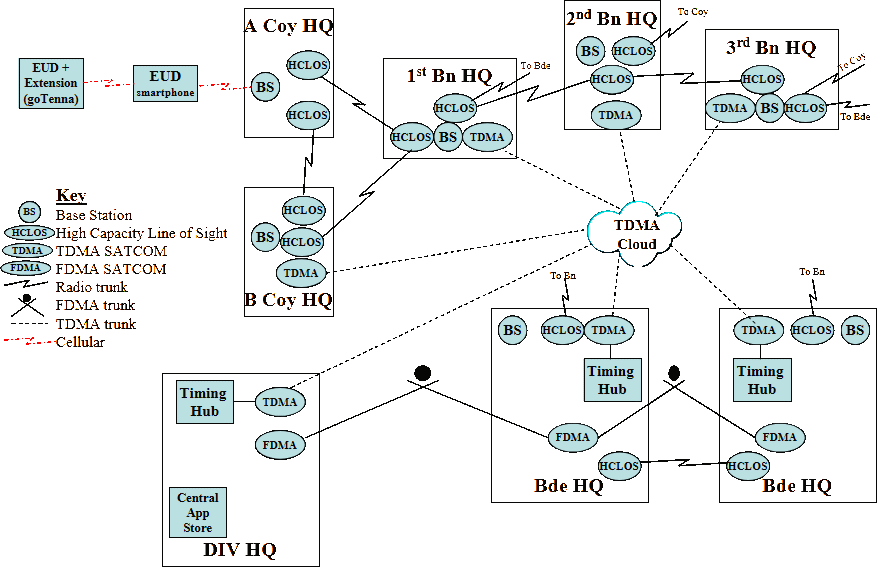
The Brigade backbone will comprise a mega-cell across the area of operations, BLOS TDMA SATCOM within the Brigade, BLOS FDMA SATCOM linking high capacity nodes and the HCLOS bearer within the Brigade and down to Company. Figure 5 outlines the network from an EUD to the Divisional HQ. The smartphone can also establish a MANET with range extension provided by GoTenna that pairs smartphones via Bluteooth Low Energy extending range without cell towers or Wi-Fi through a radio link at 151-154MHz; the transmission path is encrypted using Advanced Encryption Standard (AES)[34]. At the lowest tactical level femto, pico and micro-cells will support Sections, Platoons and Companies, macro-cells will support Battalions, whilst macro-cells and a mega-cell will support the Brigade. The overlaid design has been developed to provide single-hop connectivity on the battlefield.
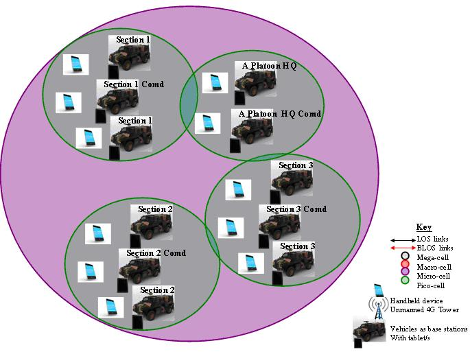
The broad network design provides a mobile network that connects vertically to enable C2, and horizontally to enable rapid task reorganisation. The first step in design was support to a Platoon, Figure 6. This support illustrates the 4G LTE+ pico or femto-cell design connecting the Platoon. The data network relies on cell base stations and smartphone range extension, overlaying the voice command net.
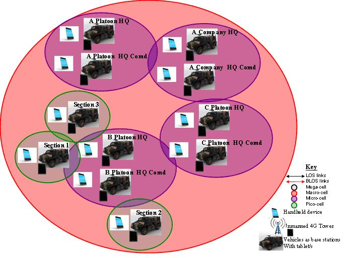
The second step for this architecture is support to an Infantry Company. Figure 7 illustrates the provision of micro-cells and a possible macro-cell to the Company. Due to the number of repeaters and base stations, CoMP will be an important capability at the Company level to route traffic. A HCLOS backbone can be employed in the concentrated scenario to connect base stations with a TDMA SATCOM backbone employed for dispersed Company operations and to directly connect to flanking units.
The third step is support within a Battalion, Figure 8. This architecture overlays a macro-cell on the Battalion for concentrated operations and a mega-cell for dispersed Battalion operations. HCLOS and TDMA SATCOM backbone trunks are provided from the Company HQ to the Battalion HQ. This solution enables dispersed and concentrated operations. EPLRS can not meet this dispersed scenario without a significant number of repeater sites.
The final step is the Brigade architecture, previously outlined at Figure 5. The Brigade construct employs significant TDMA SATCOM and HCLOS trunks to link 4G LTE+ islands, managed by a Combat Signal Regiment. The backbone is key to the success of operations. The mega–cell overlays the entire Brigade; however, it is the TDMA SATCOM structure that promotes single hop connectivity between major fighting elements (Combat Teams and Battle Groups).
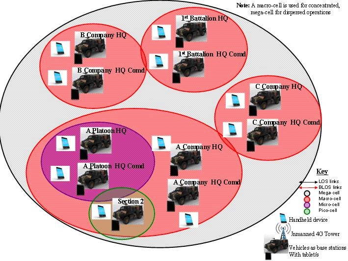
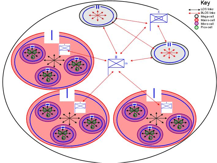
- Supporting the concentrated operational scenario. This scenario builds a standard overlaid cellular architecture employing pico, femto, micro, macro and mega-cells. The pico and/or femto-cell is at the Section/Platoon level and provides high capacity bandwidth at short distances. The micro/macro-cells are at Company, the macro/mega-cell at Battalion and Brigade. Cellular clusters are connected via a HCLOS primary path and an alternate TDMA SATCOM BLOS mesh. Figure 9 outlines support to this scenario. The cellular solution and EPLRS will meet the requirements of a concentrated scenario. However, the cellular solution will not require the number of repeating hops that EPLRS demands. The cellular architecture achieves single hop connectivity through cellular base station design and a high capacity bearers to reduce the degradation experienced per hop by EPLRS. Whilst both solutions can meet the concentrated scenario it is assessed that the cellular solution is more flexible and provides higher bandwidths.
- Supporting the dispersed operational scenario. This scenario is assessed as the most probable for ADF operations, specifically Army. It relies on BLOS connections; as such, the TDMA SATCOM and the mega-cell backbone is critical. To support this scenario the concentrated solution is first employed with an overlaid mega-cell and TDMA SATCOM BLOS capability. This option establishes additional HCLOS trunks through the insertion, predominantly by air, of unmanned HCLOS repeaters to produce a grid pattern. Figure 10 illustrates CIS support to the dispersed scenario. The solution has been designed and optimised for single hop battlefield access to enable dispersed operations. Conversely, the EPLRS data solution does not provide a BLOS data solution. Rather EPLRS relies on repeating to achieve a BLOS ‘like’ capability [35]. Thus, the EPLRS solution does not provide a BLOS capability and it is this capability gap that is critical when supporting dispersed operations, making the 4G LTE+ solution a more robust architecture than the current EPLRS solution.
- Supporting HADR. Either the concentrated or dispersed solution can be employed for HADR, an operation largely challenged by unclassified collaboration. Within this environment, EPLRS experiences releasability and bespoke hardware challenges. Conversely, the 4G LTE+ solution employs open standards and protocols that can be released to a wide range of countries and agencies. Further to this, an Open Subscriber Group (OSG), rather than a CSG, can be deployed with applications available on a commercial application store, such as iTunes. Whilst each of these organisations employ different systems the OSG provides a common backbone and the smartphone a common platform. Interoperability is greatly enhanced through establishing an open standards architecture that is software not hardware based.
To facilitate operator access into the network two primary interface capabilities will be provided, the smartphone and tablet. These devices are widely available from companies as broad as Apple, Fujitsu, Samsung and Casio and can be ruggedised through capacilities such as Otterbox, providing drop and water resistance [36]. The reduced smartphone size will facilitate multiple devices at the Section level ensuring that significant redundancy exists. The cellular solution will provide more user interfaces, that are mobile and largely intuitive.
Challenges (disadvantages)
The adoption of a new communications architecture is not without risk. Challenges include: jamming, spoofing, QoS, cyber attacks, encryption techniques, base station density, power, handover requirements and spectrum allocation.
- Jamming. Jamming denies the operator use of the spectrum. Whilst techniques such as spread spectrum and frequency hopping can decrease risk, ‘it is known that there is no widespread counter measure against jamming’ [37]. Within this architecture ‘nodes are vulnerable under jamming but nodes have a possibility to deliver messages via optional routes’ [38], similar to EPLRS. Frequency hopping can reduce risk, a feature not prevalent in cellular architectures. However, this technique is more relevant for handsets that operate at long ranges, such as HF or UHF radios [39]. The cellular architecture also seeks to operate at a higher frequency than the command voice option to decrease the possibility of barrage jamming effecting voice and data simultaneously. Jamming will be a challenge; however, no greater challenge than for current solutions and the disparate frequency use between data and voice can reduce overall network risk.
- Spoofing. The cellular solution will use GPS signals to identify locations and assist in antenna tuning. ‘Spoofing, or location falsifying attacks, refer to fake GPS signals, in which case the GPS receiver thinks that the signal comes from a satellite and calculates the wrong coordinates’ [40]. This challenge can be overcome through employing military GPS to mobile handsets. This challenge is relevant to all communications architectures.
- Cyber attacks. The employment of an IP architecture and reliance on a central application store could increase the risk of cyber attacks. Smartphones rely on applications and this will provide great opportunities; however, it will also increase vulnerabilities to external cyber attack, such as denial of service, packet dropping and misrouting [41]. As the ADF transitions its architectures, all data solutions employing IP, including EPLRS, will be vulnerable to cyber. An effective means to reduce risk is to maintain a closed data system, no connection to the internet. This solution employs a closed architecture, maintaining physical separation between the network and internet.
- Handover requirements for mobile units. Battlefield mobility demands efficient cell handovers, calling for high performance systems that can hand over at speed [42]. 4G LTE+ can assist in battlefield mobility through an umbrella cell base station design, the employment of CoMP and an efficient backbone.
- Encryption. This solution does not employ Type One encryption. However, the solution does leverage the US Department of Defence Commercial Systems for Classified (CSfC) Program, the classification of US Brigade Combat Teams (BCTs) information as Sensitive-but-Unclassified and security features employed for internet banking. The cellular solution provides a robust layered security architecture, discussed in greater detail in the last section.
- Quality of service (QoS). QoS refers to ‘availability, throughput and timeliness: including delay, jitter, reliability into bit error rate (BER), burst error, average number of retransmissions and packet loss’ [43]. These challenges can be minimised by access technology, higher bandwidth and single hop connectivity.
- Base station density requirements. To support a 4G architecture base stations must be deployed on the battlefield to provide a required density [44]. This challenge can be reduced through alternate range extension options such as the GoTenna application, leveraging off the mega-cell capability and through 4G LTE+ islands connected by a TDMA SATCOM backbone.
- Base station power requirements. Cellular base stations require more power than an EPLRS repeater. This can be mitigated through ‘dynamically minimising the number of active base stations and load balancing traffic’ [45]. Macro-cell base station power requirements may limit employment to vehicles and within Operating Bases.
- Spectrum allocation (management). The 3G/4G spectrum requires to be requested and allocated. This could be a significant cost during peacetime activities.
Opportunities (advantages)
Whilst challenges exist there are significant advantages to adopting a cellular architecture, whch include:
- Frequency reuse. 4G LTE+ employs a new frequency set from the current voice and data solution and when coupled with short transmission ranges and collision detection greater frequency reuse can be enabled [46].
- Low Probability of Intercept. The ability to avoid interception is an important military requirement. This solution exhibits Low Probability of Intercept and Low Probability of Detection due to low transmission power and the relatively short transmission range [47].
- Economies of scale. Funding is a challenge; however, upgrading a bespoke MOTS solution is expected to deliver higher costs when compared to the economies of scale provided by COTS technology [48]. It is assessed that COTS capabilities, such as smartphones, offer significant through life cost efficiencies to develop, purchase and support.
- Interoperability. Interoperability can be increased through applying adaptive techniques such as smart antennas, software defined radio, and smart receivers [49]. Further enhancement can occur by utilising open standards commercial access techniques rather than proprietary waveforms and stove piped Type One encryption techniques. This solution provides significant interoperability advantages.
- Scalability. Users can join and leave the network on an adhoc basis to meet the demands of task organising. It scales through CoMP and linking 4G islands via a high capacity backbone, providing single hop connectivity.
- Usability. Training, maintaining skills and the effects of skills fade can be mitigated through an intuitive user device. Smartphones will provide a ‘more visual and intuitive’ EUD than current radio solutions [50]. The solution employs technology that operators employ on a daily basis, it is well known, understood and accepted.
- Network agility (and relevance). Within a traditional military project the capability is employed for 20 to 30 years; this project lifecycle does not scale effectively for rapid technological change. The cellular solution seeks to reduce procurement timeframes through COTS technology, faster refresh cycles and spiral development. 4G LTE+ configuration is agile due to its software, rather than hardware, reliance.
- Multi-media. Increasingly users are relying on high bandwidth services ‘from simple voice to multimedia such as video conferencing’ [52]. Supporting bandwidth intensive, real-time, applications are a key 4G LTE+ feature facilitating fusion of battlefield multi-media.
- Survivability. The proposed network is self forming, self healing and mobile, demanding ‘quick router establishment and rerouting when a link is broken [or mobile]’ [53]. This solution establishes a random grid to enable battlefield mobility, enables direct access between handsets and CoMP to ensure QoS.
- Power. The next generation smartphones are providing excellent battery life through small lithium cells. The Samsung Galaxy S5 provides 20 hours of battery life and the Huawei Ascend provides 30 plus hours when in constant use [54]. When operating on extended patrols the batteries can be charged by solar power sources such as Solio Classic2 or Gomadic SunVolt [55]. Further to this, the small size of a smartphone battery allows soldiers to carry multiple batteries, at a lesser weight than EPLRS. The provision of longer life batteries, their smaller form factor and the ability to solar recharge batteries whilst on patrol makes the cellular architecture an extremely attractive option for dismounted patrols.
- Capacity to carry communications equipment. There is a basic limitation on equipment carriage, mounted and dismounted. Mobility influences devices (size, power requirements, display and shape), networks and services [56]. A smartphone, with its small form factor and battery size, is assessed as an extremely functional data solution for the dismounted soldier.
- Cloud computing and big data. Cloud computing provides hardware and software solutions from a centralised location. It is a model for enabling on-demand network access to a shared pool of configurable resources (networks, servers, storage and applications) [57]. The 4G LTE+ solution will employ a private cloud, where infrastructure is provisioned for ‘exclusive use by a single [ADF] organisation comprising multiple consumers’ [58]. Data storage will be a cloud approach for centralised applications, such as deliberate targeting, and decentralised for distributed applications, such as dynamic targeting. The feasibility of a solely cloud based architecture has been discounted; however, it is an important consideration for those applications demanding big data, such as FMV. It is in this facet that a high bandwidth cellular solution will outperform traditional radio networks and enable emerging platforms demanding big data.
- Leveraging off commercial research and development (R&D). R&D is a costly undertaking, particularly when conducted in isolation from other users, such as when employing bespoke MOTS solutions. Currently, the commercial market is spirally developing emerging cellular technologies including new theories, algorithms, architectures, standards and protocols, to continue to attract consumers [59]. This investment is not occurring at the same rate in traditional Defence, MOTS, acquisition. The cellular solution leverages off commercial market research and places significant weight in the continued spiral development of cellular technology. Continued competition between Tier One commercial companies, such as Apple, Samsung and Google, is extremely healthy for the adoption, continued development and replacement of Army’s data network. If Defence can be responsive and tap into commercial advancements 4G LTE+ offers a unique opportunity.
Security FEATUREs
A layered approach to security is recommended; however, the core security architecture is based on VPNs, Suite B encryption, rather than traditional Type One encryption. The NSA approved Commercial Solutions for Classified (CSfC) Program provides the basis for the dynamic multiple VPN security architecture. The CSfC outlines that a VPN ‘protects classified information as it travels across either an untrusted network or a network of a different classification level’ [60]. The CSfC solution achieves transmission surety and data integrity through ‘two nested, independent IPSec tunnels ... first by an Inner VPN Component, and then by an Outer VPN Component’, that maintains VPN isolation, as illustrated at Figure 11 [61]. The VPN solution can meet the transmission security requirements, vice Type One encryption, for the 4G LTE+ architecture and dynamically assign bandwidth and scale as end point numbers increase through point to multi-point and/or point to cloud VPNs.
![Generic VPN solution [62].](/journals/journal-of-battlefield-technology/volume-18/issue-03/assets/18-3-2-brown/figures/figure11.gif)
The VPN solution. A mixture of central and distributed functions will be employed. Central certificate management will occur with Secure Shell Version 2 (SSHv2) Transport Layer Security employed prior to being routed via the Outer VPN to the central location that holds the CA; this allows a multiple endpoint VPN solution that does not trust the transmission network and can resize VPNs dynamically, Figure 12 [63]. The provision of dual VPNs provides redundancy if a VPN fails to ensure red data does not traverse the black network.
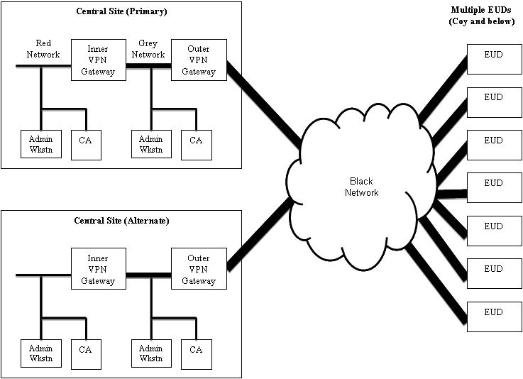
Certificates and key management. Certificates assist in verifying that authorised users access the network. ‘The VPN solution provides mutual device authentication between VPN components through public key certificates ... a remote EUD must authenticate to the network before gaining access to any data’ [64]. Certificates will be required at the end of the IPSec tunnels forming the Inner and Outer VPNs. Certificates will be available on the network and out-of-band for the initial issue of certificates [65]. Each VPN will also contain revocation information and conform to the NSA endorsed Public Key Infrastructure (PKI) employing Elliptic Curve Digital Signature Algorithm (ECDSA) signatures [66]. Certificates are essential on a modern IP network and if this solution is to connect to the ADF Defence Secret Network (DSN) or US SIPRNet they will be madatory.
Ports and protocols. The VPN solution will leverage off open standards based ports and protocols. ‘Standards based routing’, including Open Shortest Path First (OSPF), Border Gateway Protocol (BGP) and Generic Routing Encapsulation (GRE) will be employed allowing conformant layer 2 protocols such as Address Resolution Protocol (ARP), whilst limiting layer 3 protocols [67]. Ports and protocols will be enabled to allow functionality across the network after a risk assessment is conducted on vulnerabilities.
Malicious signalling traffic. Device hardening can mitigate unauthorised access. However, malicious signalling from other mobile phones, particularly hijacked phones demands consideration [68]. Currently, the majority of security measures focus on the Operating System (OS) and this will not mitigate this risk. The establishment of a Virtual Modem (VM) to protect the baseband signalling through the partitioning of the baseband and OS can protect the communications interface into the network (isolating kernel level attacks) [69]. This option builds on the VM instances establishing Inner and Outer VPNs. By employing virtualisation employing type 1 (native) hypervisor, the addition of a VM can be run within the smartphone. This option will provide data security through VPNs and mitigate signalling attacks via filtering signals leaving the smartphone.
Multiple layers of security from different vendors. ‘The use of multiple vendors reduces the likelihood that any one vulnerability can be exploited to attack the full solution’ [70]. Multiple vendors will be sourced for equipment and software implementation.
Limiting IP address access to the network. IP addresses will be filtered by establishing a closed network employing known IP addresses. Currently, malware can be disguised through a ‘game, security patch or desirable application’, a closed network and the management of an ADF application store can significantly reduce this risk [71]. In addition, cells will provide a CSG whereby handsets require pre-registration, rather than an OSG where any handset has access to base stations [72]. Closed access can assist in hardening a network.
Filters. External threats, in particular rogue traffic, will be mitigated through port filters native to the VPN gateways blocking traffic going to unexpected ports and/or without an allocated network IP address [73]. The VM will also have a filter to reduce signalling traffic from individual smartphones and the risk of network jamming by hijacked resources.
Data at rest capability. Data on a smartphone requires protection in the case of loss or compromise. Current solutions available include: the File System in User Space Encryption (FUSE) that protects removable and persistent storage on Android platforms by encrypting the data at rest [74]. Data at rest capabilities will ensure that the device is Unclassified at rest and reduce data loss risk from a compromised device.
Physical security password. Passwords and passcodes will be implemented; however, these security measures are relatively weak when employed in isolation. To improve access protection a biometric means of verification is recommended; ‘keystroke biometrics on an onscreen number pad’ that identifies users through their own style of typing or via facial recognition could be employed [75]. Mission critical applications, such as targeting and COP may require an additional password prior to access, single sign on (SSO) can be provided if appropriate.
A Central Application Store. A central ADF application store will demand that applications are digitally signed and released prior to being available for an operator to download [76]. Only cleared applications will be available, limiting the risk of malicious content.
Application isolation [77]. Isolation will be employed to further mitigate the risk of downloading a malicious application. Isolation separates processes and file system access so that each application can run independantly.
Separation of administration workstations. To assist in mitigating malware and untrusted updates, separate administration workstations and CAs will be established on the grey and red networks, including outbound filters to monitor traffic [78]. Administrator responsibilities will also be separated.
Personnel and auditing. Approved personnel will audit the network to target passive and active threats.
Screening router [79]. A screening router is employed to filter packets and identify IP addresses from outside the closed network. The screening router would be located adjacent to the black network.
Intrusion Detection System (IDS) / Intrusion Prevention System (IPS) [80]. IDS/IPS is to be located on the Grey Network between the VPN Gateways of the primary and alternate central sites. This capability adds further redundancy for the detection of malicious activity.
CONCLUSION
The 4G LTE+ architecture provides a scalable, robust, efficient and effective communications solution to the ADF, specifically the Army. The solution builds on a comprehensive overlaid architecture providing cellular access via a 4G LTE+ closed subscriber group to the tactical user. It employs high capacity short range cells, femto and pico-cells, at the lowest tactical levels scaling to micro and mega-cells to support broader Battalion and Brigade requirements. Base stations are provided on mobile platforms, such as the PMV and helicopters, and via fixed cellular towers inserted on the battlefield. These base stations are designed to provide a random grid pattern across the battlefield to promote mobility. Base stations are then linked via a primary TDMA SATCOM backbone for a BLOS capability, a capability lacking in the EPLRS system. The architecture then provides an alternate HCLOS backbone. The cellular architecture has been developed to build a high capacity network facilitating single hop battlefield access.
Whilst EPLRS employs Type One encryption it lacks the robust security architecture developed within the 4G LTE+ system. The cellular architecture builds on the Suite B encryption provided by dual VPNs with certificates, PKI, biometrics, intrusion detection, the remote updating (pushing) of patches and an Unclassified at rest data capability in the smartphone. Further to this, it removes the nexus betwen the BTN and LTN still present in the EPLRS solution, providing a converged multi-media end user platform. The 4G LTE+ cellular solution is optimised as a data network and can enable data functions such as email and chat, with emerging data requirements of video messaging and FMV; EPLRS is not optimised to provide this access.
The cellular architecture outlined meets the broad scenario requirements, seven specified goals and key IERs, and is recommended to replace the current EPLRS solution. It is a self contained, closed network capable of deployment to austere environments, providing time critical applications efficiently. The open standards employed for encryption and access techniques lends the solution to be broadly interoperable and it leverages off a COTS based solution, including the significant R&D being undertaken by Tier One technology giants, such as Microsoft, Apple and Samsung. The broad risks are similar between an EPLRS and cellular solution; however, the opportunities contained within a cell architecture are significant. Overall the system is scalable, survivable (multi-path) and secure via multiple techniques. The cellular solution meets the capability goals and diverse scenario options presented to the Army by government.
The 4G LTE+ cellular architecture provides an agile, usable, interoperable system providing time critical, high capacity information across the spectrum of conflict to support the commander in an austere environment.
References
[1] Ryan, M. and M. Frater, 2007, Battlefield Communications System, Argos Press, Canberra, p. 150.
[2] This includes regions in the Middle East, Central or South Asia and/or Africa. Department of Defence, 2009, Force 2030: Defending Australia in the Asia Pacific Century, Australian Government, p. 60.
[3] Poirer, J.A., E. Bates, and M. Tempestilli, 2003, How Much is a Pound of C4ISR Worth, United States Military, Arlington, Virginia, annex A, slide 18.
[4] United States Army, 2005, FM-1: Vision for the Army, Department of the Army, Fort Leavenworth, paragraph 4-4.
[5] Ryan and Frater, Battlefield Communications , pp. 106-115.
[6] Ibid, pp. 106-162.
[7] Ibid, pp. 145-147.
[8] Ibid, p. 158
[9] Ibid, p. 158.
[10] Mann, ‘Modern Military Threats: Not All They Might Seem’, p. 57; Department of Defence, Force 2030, p. 79.
[11] http://www.defenseindustrydaily.com/iais-iview-uav-partners-wins-australias-jp129-contract-updated-01620/ accessed on 17 Oct 14.
[12] Department of Defence 2013. Defence White Paper 2013, Commonwealth of Australia, p. 86.
[13] Barber, E., and N. Parsons, 2009, ‘A Performance Model to Optimise the Capability Choices Made in the Procurement Phase within the Australian Defence Force’, International Journal of Defence Acquisition Management, Vol 2, p. 35.
[14] Sun, J.Z., J. Sauvola and D. Howie, 2001, Feature in Future: 4G Visions from a Technical Perspective, IEEE, pp. 2-4.
[15] accessed on 21 Aug 15; Huang, J., F. Qian, A. Gerber, Z.M. Mao, A. Sen, O. Spatscheck, 2012, A Close Examination of Performance and Power Characteristics of 4G LTE, University of Michigan, Michigan, p. 1.
[16] Sun et al, ‘Feature in Future: 4G Visions’, p. 3; Huang et al, A Close Examination of Performance and Power, p. 1.
[17] accessed on 20 Aug 15.
[18] Sun et al, ‘Feature in Future: 4G Visions’, p. 4.
[19] Andrews, J., H. Claussen, M. Dohler, S. Rangan and M.C. Reed, 2012, Femtocells: Past, Present and Future, IEEE Journal on Selected Areas in Communications, Vol 30, No 3, April, p. 497.
[20] Fan, G., J. Zhang, 2004, A Novel Deometric Diagram and Its Applications in Wireless Networks, University of Mississippi.
[21] Fan, G., J. Zhang, 2004, A Novel Deometric Diagram and Its Applications in Wireless Networks, University of Mississippi, USA, accessed at on 02 Oct 14.
[22] Li, X.J., B.C. Seet, and P.H.J. Chong, 2008, ‘Multihop. Cellular Networks: Technology and Economics’, Computer Networks 52, p. 1826; Rajesh, A., and N.MM. Kumar, 2014, ‘Multi-Level Trust Architecture for Mobile Adhoc Networks Based on Context-Aware’, Journal of Theoretical and Applied Information Technology, Vol 59, No 2, p. 1826.
[23] Al-Omari, S.A. and P. Sumari, 2010, ‘An Overview of Mobile Ad Hoc Networks For The Existing Protocols and Applications’, Journal on Applications of Graph Theory in Wireless Adhoc Networks and Sensor Networks, Vol 2, No 1, p. 87; Li et al, ‘Multihop Cellular Networks’, p. 1825.
[24] Nurmi et al, ‘Tactical Application of Heterogeneous Ad Hoc Networks’, p. 3.
[25] Li et al, ‘Multihop Cellular Networks’, p. 1826; Rajesh et al, ‘Multi-Level Trust Architecture for Mobile Adhoc Networks’, p. 275; Al-Omari, et al, ‘An Overview of Mobile Ad Hoc Networks’, pp. 87-89; Nurmi et al, ‘Tactical Application of Heterogeneous Ad Hoc Networks’, p. 1.
[26] Li et al, ‘Multihop Cellular Networks’, p. 275.
[27] Ibid, p. 1826.
[28] Ibid, pp. 1825-1827.
[29] Ibid, p. 1828.
[30] Hoydis, J., M. Kobayashi, and M. Debbah, 2011, ‘Green Small-Cell Networks’ , IEEE Vehicular Technology Magazine, March 2011 , pp. 37-38.
[31] Phase Zero is shaping the battlespace; Phase One is deterring, Phase Two is seizing the initiative, Phase Three is dominating the enemy, Phase Four is stabilising the area and Phase Five is enabling civil authority. US Department of Defence, 2011, Joint Publication Five Joint Operation Planning, Defence, Washington D.C. pp. xxiiv- xxiv.
[32] Bleicher, A. 2014, 4G Gets Real, p39 accessed at http://www.cacs.louisiana.edu/~perkins/csce575/papers/LTE-ieee-spectrum.pdf on 12 Sep 14, p. 43.
[33] Carroll, A, and G. Heiser, 2014, An Analysis of Power Consumption in a Smartphone, NICTA and UNSW p. 1, accessed at http://static.usenix.org/event/usenix10/tech/full_papers/Carroll.pdf on 20 Aug 15.
[34] http://gotenna.com/pages/how-it-works accessed on 21 Aug 14.
[35]http://www.dote.osd.mil/pub/reports/FY2011/pdf/army/2011fbcb2.pdf accessed on 20 Aug 15.
[36] http://www.cnet.com/pictures/top-20-tough-iphone-4-and-4s-cases-photos/ accessed on 15 Aug 15; Casio Computers, 2014, Hardened Casio Systems, Presentation to the Multi-National Communications Interoperability Program, Tokyo, Japan 15 Aug 14; NEC, 2014, NEC Emergency Mobile Network, Presentation to the Multi-National Communications Interoperability Program, Tokyo, Japan 15 Aug 14; Fujitsu, 2014, Technology Demonstration by Fujitsu, Presentation to the Multi-National Communications Interoperability Program, Tokyo, Japan 15 Aug 14.
[37] Kim, Y.S., P. Tague, H. Lee, and H. Kim, 2012, Carving Secure Wi-Fi Zones with Defensive Jamming, Research Paper, Carnegie Mellon University, Silicon Valley, USA, p. 1.
[38] Nurmi, J. and M. Suojanen. 2014, ‘Tactical Application of Heterogeneous Ad Hoc Networks – Cognitive Radios, Wireless Sensor Networks and COTS in Networked Mobile Operations’, COCORA 2014: The Fourth International Conference on Advances in Cognitive Radios, p. 3.
[39] Ibid, p. 4.
[40] Khan, A.H., M.A. Qadeer, J.A. Ansari, and S. Waheed, 2009, ‘4G Next Generation Wireless Network, International Conference on Future Computer and Communications’, IEEE Computer Society, p. 336; Rajesh, et al ‘Multi-Level Trust Architecture for Mobile Adhoc Networks’, p. 277.
[41] Khan et al, ‘4G Next Generation Wireless Network’, p. 336; Rajesh et al, ‘Multi-Level Trust Architecture for Mobile Adhoc Networks’, p. 277.
[42] Nurmi et al, ‘Heterogeneous Ad Hoc Networks’, p. 4.
[43] Yiping, C. and Y. Yuhang 2007, A New 4G Architecture Providing Multimode Terminals Always Best Connected Services, IEEE Wireless Communications, April 2007, p. 37; Rajesh et al, ‘Multi-Level Trust Architecture for Mobile Adhoc Networks’, p. 277.
[44] Zhou, S., J. Gong, Z. Yang, Z. Niu and P. Yang. Green Mobile Access Network with Dynamic Base Station Energy Saving, p. 1; Yiping, C. et al, New 4G Architecture, IEEE Wireless Communications, April 2007, p. 37-38.
[45] Zhou et al, Green Mobile Access Network, p. 1.
[46] Nurmi et al, ‘Heterogeneous Ad Hoc Networks’, p. 3.
[47] Nurmi et al, ‘Tacti Heterogeneous Ad Hoc Networks’, p. 3.
[48] Nurmi et al, ‘Heterogeneous Ad Hoc Networks’, p. 4.
[49] Sun et al, ‘Feature in Future: 4G Visions’, p. 4.
[50] Khan et al, ‘4G Next Generation Wireless Network’, p. 336.
[51] Sun et al, ‘Feature in Future: 4G Visions’, p. 5.
[52] Li, et al ‘Multihop Cellular Networks’, p. 1825; Khan et al, ‘4G Next Generation Wireless Network’, p. 335.
[53] Takeuchi, T. 2014, NEC Presentation to Multinational Communications Interoperability Program, New Sanno Hotel, Tokyo, Japan, slide 13.
[54] http://www.pcmag.com/article2/0,2817,2459645,00.asp accessed on 17 Aug 15.
[55] Petronzio, M. 2013, Eight Solar Powered Mobile Charges, accessed at http://mashable.com/2013/04/05/mobile-solar-power/#gallery/8-inventive-solar-powered-smartphone-chargers/520c8dfeb589e476850004ff on 17 Aug 15; http://www.news.com.au/technology/environment/anu-solar-technology-replacing-army-troops-heavy-batteries/story-fnjww1so-1227039039117 accessed 28Aug15.
[56] Sun, J., and J. Sauvola, 2002, On Fundamental Concept of Mobility for Mobile Communications, IEEE, p. 2.
[57] Mell, P., and T. Grance, 2011, The NIST Definition of Cloud computing, National Institute of Standards and Technology, US Department of Commerce, pp. 2-3; Above the Clouds: A Berkeley View of Cloud Computing, accessed at http://ftp.cs.duke.edu/courses/cps296.4/compsci590.4/fall13/838-CloudPapers/AboveTheClouds.pdf on 2 Oct 14.
[58] Mell et al, The NIST Definition of Cloud Computing, p. 3.
[59] Sun et al, ‘Feature in Future: 4G Visions’, p. 1.
[60] National Security Agency, 2013, Commercial Solutions for Classified Virtual Private Network Capability Package, National Security Agency Information Assurance Directorate, US Government, p. 2.
[61] Rosen, E., and Y. Rekhter, 2006, BGP/MPLS IP VPN, Network Working Group, Cisco Systems and Juniper Networks, p. 27-28; National Security Agency, CSfC, p. 3.
[62] National Security Agency, CSfC, p. 3.
[63] Gleeson, B., A. Lin, J. Heinanan, T. Finland, G. Armitage, A. Malis, 2000, A Framework for IP Based Virtual Private Networks, Network Working Group, Nortel Networks and Lucent Technologies, p. 7; Duffield, N.G., P. Gowyal, A. Greenberg, P. Mishra, K.K.Ramakishnan and J.E. Van Der Merwe, 2002, A Flexible Model for Resource Management in Virtual Private Networks, AT&T Labs, New Jersey, pp. 95-98; Duffield, N.G., P. Gowyal, A. Greenberg, P. Mishra, K.K.Ramakishnan and J.E. Van Der Merwe, 2002, A Flexible Model for Resource Management in VPNs, IEEE/ACM Transactions on Networking, Vol 10, No 5, pp. 679-683.
[64] National Security Agency, CSfC, p. 12.
[65] National Security Agency, CSfC, p. 12.
[66] National Security Agency, CSfC, p. 19.
[67] National Security Agency, CSfC, p. 12.
[68] Mulliner, C., S. Liebergeld, M. Lange, and J-P. Seifert, 2012, Taming Mr Hayes: Mitigating Signaling Based Attacks on Smartphones, Research Paper, Berlin University, p. 1.
[69] Mulliner et al, Taming Mr Hayes, pp. 1-2; Selhorst, M., C. Stuble, F. Feldmann and U. Gnaida, 2010, Towards a Trusted Mobile Desktop, Trust 10: International Conference, Berlin, pp. 78-94; Schmidt, A.U., N. Kuntze and M. Kasper, 2008, On the Deployment of Mobile Trusted Modules, Wireless Communications and Networking Conference, IEEE, pp. 3169-3174; Klein, G. K. Elphinstone, G. Heiser, J. Andronick, D. Cock, P. Derrin, D. Elkaduwe, K. Engelhardt, R. Kolanski, M. Norrish, T. Sewell, H. Tuch, and S. Winwood, 2009, seL4: Formal Verification of an OS Kernel, ACM Symposium on Operating Systems Principles, ACM, pp. 207-220.
[70] National Security Agency, CSfC, p. 11.
[71] Wang, Y, K. Streff, and S. Raman, 2012, Security Threats and Analysis of Security Challenges in Smartphones, Dakota State University, IEEE, pp. 2-3.
[72] Andrews, J., H. Claussen, M. Dohler, S. Rangan and M.C. Reed, 2012, Femtocells: Past, Present and Future, IEEE Journal on Selected Areas in Communications, Vol 30, No 3, April, p. 500.
[73] National Security Agency, CSfC, p. 22.
[74] Wang, Z., R. Murmuria and A. Stavrou, 2012, Implementing and Optimizing an Encryption Filesystem on Android, Mobile Data Management, 2012 IEEE Conference, pp. 52-54 accessed at http://dl.acm.org/citation.cfm?id=2411391 on 24 Aug 15.
[75] Wilson, M, and L. Chen, 2011, Securing Sensitive Data Stored on Smartphones: Using Face Recognition to Unlock Mobile Devices, Sam Houston State University, pp. 1-2. Pocovnicu, A. 2009, Biometric Security for Cell Phones, Informatica Economica, vol 13, no 1, pp. 57-63.
[76] Barrera, D., and P.C. Van Oorschot, 2010, Secure Software Installation on Smartphones, p. 2 accessed at http://people.scs.carleton.ca/~paulv/davidb.pdf on 18 Aug15.
[77] Barrera et al, Secure Software on Smartphones, p. 2.
[78] National Security Agency, CSfC, p. 22.
[79] National Security Agency, CSfC, p. 19.
[80] National Security Agency, CSfC, p. 19.
Lieutenant Colonel Kurt Brown is an officer in the Royal Australian Corps of Signals. He has served within the tactical environment at the 3rd and 7th Brigade, at Headquarters Joint Operations Command, within the Chief Information Officer Group and on exchange with the United States Army 11th Signal Brigade. He has served on operations in Iraq, Afghanistan and Timor Leste. LTCOL Brown is a Staff College graduate and holds a Master of Engineering Science (Electrical), Master of Business and Military Studies. His email is kurt.brown@defence.gov.au.