
Volume 18, Number 3, November 2015
Effect Of Metallic And Non-Metallic Casings On Spatial Distribution Of A Fragment Generator Warhead
- 1 Armament Research & Development Establishment, Dr. Homi Bhabha Road, Pashan, Pune – 411021, India.
- 2 Defence Institute of Advanced Technology, Girinagar, Pune – 411025, India.
Abstract
This paper reports on studies into the effect of casing material on the fragment spatial distribution of a Fragment Generator Warhead (FGW). Usually, metals are used for the manufacture of the warhead casing which is manufactured using conventional methods. Recently, FGWs have been designed with complex contours to meet the specific requirements of interceptor missiles. Manufacturing of such casings using conventional methods has been observed to be difficult and time consuming. Alternatively, the casings can be manufactured with ease by rapid prototyping (RP) methods using non-metallic materials. In order to study the effect of metallic and non-metallic materials, the authors conducted a comparative performance analysis of aluminium and Dura Form Glass Filled (DFGF) warheads manufactured by conventional and RP methods, respectively. The warheads are designed to yield a fragment beam of 32° in azimuth and 20° in elevation. The experimental details are presented and it is concluded that uniform fragment spray is only yielded from the metallic casings manufactured by conventional methods.
Introduction
Forward firing warhead is one of the different types of directional warheads being deployed in interceptor missiles to neutralize the ballistic missile class of targets. The end game interception logic for an interceptor calls for accurate information of fragment spatial distribution due to high closing velocities and low miss distances ranging between a few metres to tens of metres. The fragment spatial distribution can be estimated from the fragment projection angle and velocity with reference to its position on the warhead surface [1,2].
The fragment generator warhead (FGW) can be designed to meet the tailored spatial distribution for the specified requirements of the interceptor. The warhead design parameters are the explosive charge mass (C) to fragmenting disc metal mass (M) ratio (C/M), the charge length (L) to diameter (D) ratio (L/D), charge properties, initiation location, contour of fragmenting disc surface, number of fragment layers, detonation wave front contour and casing configuration. For the development of performance prediction models and establishing the expected performance of the designed warhead, number of experiments needs to be conducted. The preferred casing materials are steel, aluminium, and plastic [3]. The pre formed fragments are made of steel, tungsten alloy, depleted uranium, zirconium, and titanium [4]. The fragmenting surface area needs to be contoured for the desired un-symmetric fragment spatial distribution. Manufacturing such a typical contoured casing from the metal is complicated and time consuming. However, such casings can be manufactured with ease using rapid prototyping. In order to study the effect of casing material, the authors have designed the FGW with aluminium alloy and Dura Form Glass Filled (DFGF) materials. The warhead casing is manufactured using conventional machining methods for aluminium alloy and rapid prototyping based on selective laser sintering for DFGF. The casing was designed to have uniform fragment beam of rectangular size of 32° by 20°. The article presents the experiment details of performance evaluation and the observations made on fragment spatial distribution are discussed.
Details of Experiment
An FGW having a rectangular fragment beam of 320 by 200 with fragment velocity of 1,500 m/s, is considered. The design of such warheads involves a fragmenting surface contour with complex geometry and needs to be optimized based on analytical formulations and field tests. Manufacturing of such surface contours using metals by conventional methods is complicated and time consuming. Alternatively, complex shaped fragmenting surface can be manufactured in a rapid prototype (RP) machine. For the conventional method of manufacturing, aluminium alloy is considered as a potential choice of material for the casing due to its high strength to density ratio. For RP manufacturing using selective laser sintering technique, Dura Form Glass Filled (DFGF) has been selected. Authors have carried out comparative performance analysis by conducting a number of experiments. The typical properties for both materials of the casing are given in Table 1.
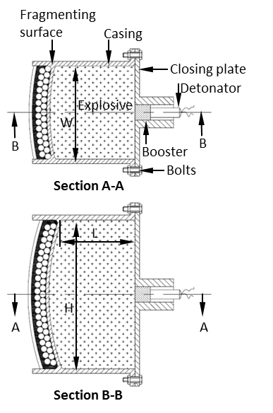
The warhead casing is 3 mm thick. The schematic of the FGW is shown in Figure 1. The contoured fragmenting surface is made as a part of the casing with 2 mm thickness having an inner spherical radius of 140 mm. The width, W, and height, H, of the casing is 60 mm and 96 mm, respectively. The fragmenting surface is laid with 4 mm steel spheres in two layers using resin mixed with iron powder. The spall mitigating layer of 2 mm thick resin mixed with iron powder and 2 mm thick aluminium alloy sheet is provided on the fragment outer surface [5]. Addition of the iron powder increases the impedance of the resin mix. When a shock wave through a fragment comes in contact with a high impedance material, the reflected wave intensity travelling back in the fragment (rarefaction) is reduced. As a result, spall is mitigated. The high explosive HMX/TNT (70/30) is filled in the casing and the closing plate is integrated to the casing by nuts and bolts. The closing plate has a provision to insert RDX/ wax (95/5) booster with a diameter of 10 mm and length of 10 mm. An electrical detonator is provided to initiate the booster. Two tests with each casing materials were carried out.
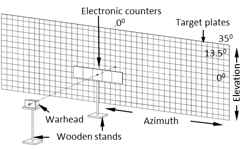
The arena test setup for the experiment to assess the spatial distribution of the fragments and fragment velocity is shown in Figure 2. The warhead was placed at a height of 1.2 m on a wooden stand. Steel targets plates were of 1.5 mm thick, height 2.4 m and width 1.2 m. Target plates were placed at a distance of 5 m from the warhead. The target plate covered 27° cone angle in elevation. To cover the fragment spatial distribution in azimuth, six target plates were placed, which covered 7.2 m in azimuth with 70° cone angle. The target plates were marked in 2° in azimuth and elevation to record fragment spatial distribution. The warhead was aligned to the centre of the target using a laser level meter. The multi-channel electronic counters were kept in front of the target plates to record initial fragment velocity. From the distance and the time record, the fragment velocity was estimated.
| Property | Aluminium alloy IS:733, Gd 65032 in WP | Dura Form Glass Filled (DFGF) |
|---|---|---|
| Tensile Strength, Yield (MPa) | 200 | 27 |
| Tensile Strength, Ultimate (MPa) | 245 | 38 |
| Percentage Elongation | 6% | 2% |
| Density (g/cm3) | 2.7 | 1.4 |
| Casing | E: 20° A: 32° | E: 24° A: 40° | E: 28° A: 48° | E: 28° A: 64° |
|---|---|---|---|---|
| Al alloy | 42% | 59% | 66% | 69% |
| DFGF | 33% | 47% | 59% | 61% |
Al: Aluminium; E: elevation angular zone; A: azimuth angular zone.
Al: Aluminium; E: Elevation angular zone; A: Azimuth angular zone
Results and Discussions
The results of the spatial distribution of fragments, using the both materials, are discussed in the section. The number of fragments laid on both the casings are 767. For analysis purposes, the data is averaged over two experiments of each casing material and given in Table 2. Even though the target plate was covering 70° cone in azimuth, there were no fragments beyond 64° cone. In elevation, the target plate height restricts the beam coverage to +13.5°. To present the data in 2° intervals, it is scaled for the zone of 120–14°. In the aluminium alloy and DFGF casings, a maximum percentage of fragments hit on the target was 69% and 61%, respectively. The remaining fragments are expected to have higher projection angles in the elevation than that which can be captured by the target. It is observed that a comparatively lower percentage of fragments on the target (70° by 27°) was recorded with DFGF casing compared to aluminium alloy casing.
The designed fragmenting surface of the warhead was symmetrical in elevation and azimuth directions. The number of fragments recorded in each 2° by 2° cone on the target was averaged for both trials and for the four quadrants. For comparison, the contoured plots of fragment distribution for aluminium alloy and DFGF casings are shown in Figures 3 and 4, respectively. It is observed from the figures that for aluminium alloy casing, the fragments spray was comparatively more uniform than the DFGF casing. In the desired fragment beam of 32° (+16°) by 20° (+100) the number of fragments in each angular zone was in the range of 1.5–2.5 and the fragment beam was coherent in aluminium alloy casing. Whereas, in case of DFGF, there were patches of fragment zones with 1–1.5 numbers, 1.5–2 numbers and 2-2.5 numbers. On comparing the fragment beam in azimuth, it is observed that in case of aluminium alloy casing, fragment sprayed up to 22° (full cone of 44°) and gradually reducing the fragments from the range of 0.5–1 numbers to 0–0.5 around 24° (full cone of 48°). For DFGF casing, the beam width in azimuth was around 2° higher compared to the aluminium casing. Similar trend is also expected in the elevation direction for both casing materials.
The observed variations are due to the differences, in casing expansion and breakage phenomenon. Since aluminium is more ductile than DFGF, it expands more before breakage. On interaction of detonation front with the fragmenting surface of the casing, the shock wave travels through it, resulting in material compression, expansion and multiple shock wave interactions. The metal case experiences stretching at a constant strain rate. The fracture occurs instantaneously and relieves the tensile stress. From the free fractured surface at zero stress, a release wave travels back in the stressed casing material. The stress release wave is referred as a Mott wave. Simultaneously, fractured surfaces from the other regions also develop such Mott waves. The phenomenon of squeezing, expanding, wave travelling, fracturing continues till casing breaks in multiple pieces and the stresses are relieved [6–8]. It is reported that an aluminium alloy tube having 3.7 mm thickness expands to 3.2 times its initial radius before explosion gas starts escaping through tube casing [9]. The probability theory for release wave propagation from the fractured surfaces predicts number of fractures and the distribution of fracture length [10]. The theory predicts that the number of fragments decreases with decreasing strain rate and material density.
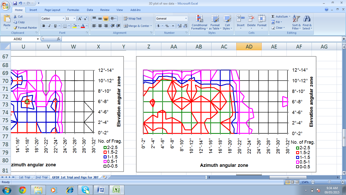
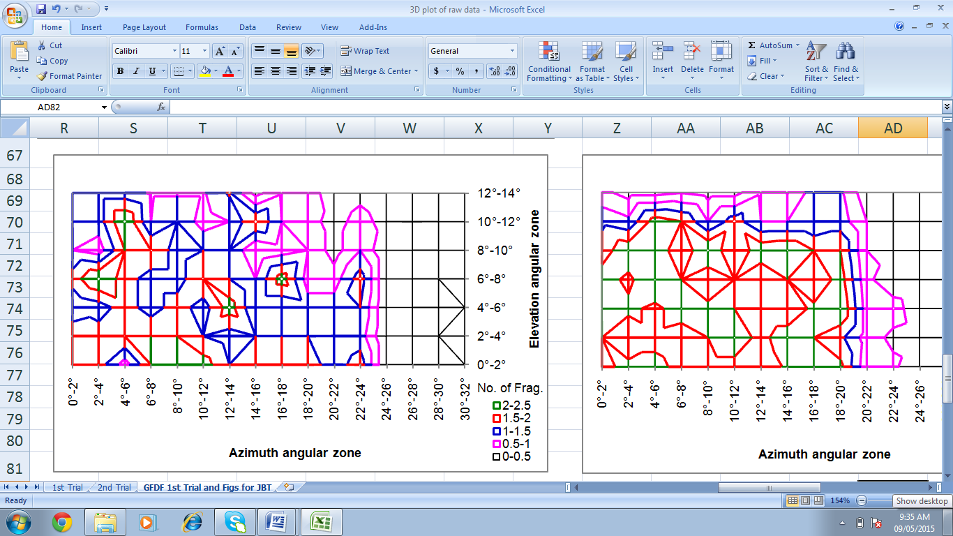
On comparing the material property for aluminium and DFGF, it is observed that the strength, percentage elongation and density of DFGF are lower than the aluminium alloy. Hence, it is expected that the DFGF material fractured early than the aluminium and lower number of fractured pieces from fragmenting surface. The larger sized DFGF pieces would have resulted in the patchy distribution observed in Figure 4.
In the case of a cylindrical charge having a fragmenting disc at one end of the cylinder and initiation at the other end, the modified Gurney Equation is used to calculate the fragment velocity [11]. The high explosive has a Gurney characteristic velocity of (2E)1/2 of 2800 m/s. The velocity correction factor c of 0.9 is considered to correct for the venting of gases through fragments [12]. The fragmenting surface is considered to be a rectangle. The equivalent diameter of 86 mm is calculated from the configuration W and H dimensions. The explosive has column length L of 47 mm. The configuration has L/D and C/M ratio of 0.55 and 2.25, respectively. The estimated velocity using (1) is 1,504 m/s.
The velocity variation of fragments from the warhead axis to the periphery depends on confinement to explosive. Lower confinement by casing material results in higher velocity variations. As the DFGF has low density than aluminium alloy, it provides low confinement resulting in more velocity variations. As the aluminium alloy casing holds the high pressure explosive gas for a longer period and expands more compared to DFGF before fracture, more energy of explosive is transferred to the fragmenting surface. As a result, it imparts higher velocity to the fragments. Thus, a higher velocity of fragments was recorded for aluminium alloy compared to DFGF casings in the central zone (+2° in elevation and +10° in azimuth). The range of fragment velocities for aluminium and DFGF were 1,407–1,581 m/s and 1,262–1,340 m/s, respectively.
Conclusions
The paper presents the experimental investigations of the fragment spatial distribution using two different casing materials. The performance of the fragment generator warheads with aluminium alloy and DFGF is test evaluated. The aluminium alloy casing is manufactured by conventional machining and the DFGF is manufactured by rapid prototyping. It is observed that the fragment spatial distribution in case of DFGF material is in patches and around 2° wider than with the aluminium alloy casing. Further, the fragment velocity in case of DFGF is around 12% lower than the aluminium alloy casing. The reason for the variation is mainly attributed to the properties of casing materials. DFGF has comparatively low in strength, percentage elongation and density than that of aluminium alloy, resulting in early fracture and bigger size casing pieces. Even though the casing of typical contoured warhead is easy to manufacture using DFGF, its fragment spray pattern is not coherent. Further, the observed fragment velocity in metallic casing is in agreement with the calculated velocity using the modified Gurney equation. Hence, the authors recommend metallic casings only to achieve uniform fragment spray and high velocity. However, the metallic casings made using the RP method may also yield proper fragment spray pattern and may be considered for future applications.
References
[1] R. M. Lloyd, Physics of Direct Hit and Near Miss Warhead Technologies, Progress in Astronautics & Aeronautics, Vol. 194, Paul Zarchan (ed), American Institute of Aeronautics and Astronautics, USA, 2001, pp. 199–274.
[2] K.D. Dhote, K.P.S. Murthy, K.M. Rajan, and M.M. Sucheendran, “Quantification of Projection Angle in Fragment Generator Warhead”, Defence Technology, 10, 2014, pp. 177–183.
[3] R.M. Lloyd, Physics of Direct Hit and Near Miss Warhead Technologies, in: Progress in Astronautics & Aeronautics, Vol. 194, Paul Zarchan (ed), American Institute of Aeronautics and Astronautics, USA, 2001, p. 79. ISBN: 1-56347-473-5.
[4] M. Held, Fragmentation Warheads, Progress in Astronautics & Aeronautics, Vol. 155, Joseph Carleone (ed), American Institute of Aeronautics and Astronautics, USA, 1993, p. 439.
[5] K.D. Dhote, P.N. Verma, and K. P. S. Murthy, “Mitigation of Fragment Spall Induced by Explosive Loading in High Performance Fragment Generators”, Journal of Battlefield Technology, Vol. 17, No. 1, Mar 2014.
[6] D. Grady, Fragmentation of Rings and Shells – The Legacy of N.F. Mott, Chapter 4: Further Features of the Mott Statistical Theory, Springer Publication, 2006, pp. 67–95.
[7] S. Levy, J.F. Molinari, and R. Radovitzky, “Dynamic Fracture of a Brittle Plate Under Biaxial Loading: Strength or Toughness Controlled?”, International Journal of Fracture, Vol. 174, 2012, pp. 203–215.
[8] K.D. Dhote, K.P.S. Murthy, K.M. Rajan, and M.M. Sucheendran, “Dynamics of Multi Layer Fragment Separation by Explosion”, International Journal of Impact Engineering, 75, 2015, pp. 194–202.
[9] G.I. Taylor, The Fragmentation of Tubular Bombs, G.K. Batchelor (ed), The Scientific Papers of G. I. Taylor, Vol. III, Cambridge at the University Press, UK; 1963. p. 387–390.
[10] D. L. Wesenberg and M. J. Sagartz, “Dynamic Fracture of 6061-T6 Aluminum Cylinders”, Journal of Applied Mechanics, Dec. 1977, pp. 643–646.
[11] R. M. Lloyd, Physics of Direct Hit and Near Miss Warhead Technologies, Progress in Astronautics & Aeronautics, Vol. 194 (Eds.: Paul Zarchan), American Institute of Aeronautics and Astronautics, USA, 2001, p. 250.
[12] Q. Lixin, Q. Ming, W. Yu, Z. Yongqing, and J. Daojian, “Dense Fragment Generator”, Propellant, Explosives, Pyrotechnics, 27, 2002, pp. 267–278.