
Volume 18, Number 2, July 2015
Case Study: Simulation Of A Honeycomb Floor Panel Within An Mbt Hull
- 1 Scientist - CVRDE, DRDO, Ministry of Defence, Govt of India, Avadi, Chennai-600 054, Tamilnadu, India.
- 2 Centre for Simulation and Analytics, Cranfield University, Defence Academy of the United Kingdom, Shrivenham, SN6 8LA, UK.
Abstract
This paper investigates the effectiveness of honeycomb sandwich structure in an MBT hull through a Finite Element Analysis based study. Two hulls, one with steel floor plate and the other with a honeycomb-sandwich floor plate made of aluminium alloy were modelled. Both these hull models were subjected to the same loads and boundary conditions and the resulting stress and deformation results are discussed and compared. It was observed that although the honeycomb sandwich floor plate did undergo higher stress and deformation compared to the steel floor plate, the values were within safe design limits. In addition to this, using these honeycomb structure would result in a substantial mass saving as found from the study. Finally, this paper also covers the practical difficulties associated with incorporating honeycomb structures in MBT hull construction and recommends future courses of investigation.
Introduction
The main battle tank (MBT) was originally designed for a conventional combat, but has now metamorphosed into a platform capable of engaging targets even in urban areas. As the threat profile in such areas is deadly, military designers are incorporating new armour systems into MBTs to better protect the crew. However, such protection tends to increase the combat mass of the tank, as evident from the contemporary tanks such as the M1A2 and Challenger 2, approaching 70 tons—the increased weight reduces draw bar pull of these tanks in difficult terrains [1]. Hence, a global search has begun to identify newer and lighter materials that can offer both mass reduction and superior protection. It is against this background that this paper explores the feasibility of incorporating light-weight honeycomb structural panels within an MBT hull structure, in this case as a floor panel.
Honeycomb structural panels are widely used in the aircraft industry due to their high stiffness-to-mass ratio. They, replace the heavier sheet metal and stringer approach, thus reducing the structure mass. In addition, they are also widely used for energy absorbing applications such as mine blast. However, their usage in MBT structures is limited due to its low absolute structural rigidity and inability to withstand projectile impacts due to low density as compared to steel. Nevertheless, there are areas in a MBT hull that are not subjected to projectile impact where light weight honeycomb panels can be explored as alternatives which form the core objective of this paper. This objective is justified through a finite element analysis (FEA) on a typical MBT hull model for which static strength and stiffness was evaluated. However, dynamic studies such as vibration, explosive shock is left for future scope and do not form a part of this investigation.
MBT HULL CONSTRUCTION And FLOOR PLATE
A MBT is composed of two main structures namely the hull and turret as shown in Figure 1. The hull structure or the chassis is a closed box section made of steel plates. Of the several plates of varying thickness, three plates namely the side, top and floor plate provide the basic strength and stiffness required for the structure. In the hull structure, the top and side plates must withstand projectile impacts from small and medium calibre weapons whereas the floor plate does not face these threats due to its location.
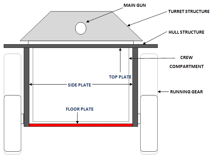
A typical floor plate made of steel measures 4500(L) x 2000(W) x 18(H) mm and weights 1200 kg. Such a floor plate if replaced by a honeycomb sandwich panel can provide a mass saving of up to 50%. However, the static stress and deflection on the overall hull due to this replacement is investigated in this paper as given in the proceeding sections.
HONEYCOMB PANEL BEHAVIOR
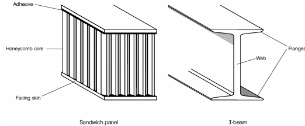
A honeycomb sandwich panel behaves very similarly to an I-beam with the facing skins of the panel performing the role of the flanges and the honeycomb core performing the role of the web, as shown in Figure 2. The facing skins of the panel carry the bending load with, for example the top skin loaded in compression and the bottom skin in tension whereas the honeycomb core carries the shear load [2].
In addition to resisting the shear loads, the core also increases the second moment of area (geometrical stiffness) of the structure by spacing the facing skins, and giving continuous support to the facing skins thus to produce a uniformly stiffened panel. The core-to-skin adhesive rigidly joins the sandwich components and allows them to act as one unit with a high relative torsional and bending rigidity.
APPROACH TO THE STUDY
The following approach was used to carry out this study:
- Carry out measurements on a MBT hull.
- Create a 3-D geometrical model with these measurements and estimate hull structure mass.
- Collect mass data on sub-systems and their locations.
- Carry out mass budgeting.
- Select the honeycomb panel material.
- Select the honeycomb core parameters, material and optimise thickness.
- Estimate the load cases.
- Create free body diagrams for applying static loads.
- Create 3-D geometrical model for the honeycomb panel.
- Create another 3-D geometrical model of the hull structure incorporating the above honeycomb panel instead of solid steel floor plate.
- Assign material models.
- Generate a FE mesh for both the geometrical models, assuming linear elastic properties.
- Apply the same load and constraints for both models.
- Carry out a static structural stress and deformation analysis on both the hull models.
- Compare and contrast both these results.
GEOMETRICAL MODEL AND MASS BUDGETING OF HULL
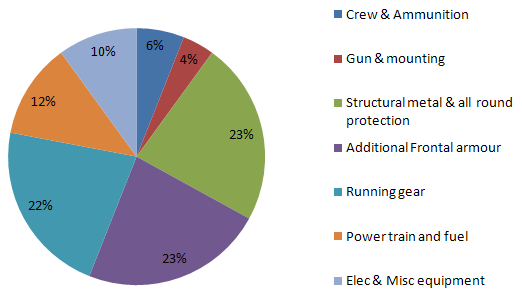
Since intricate information regarding system data and dimensions were not available for contemporary MBTs, it was decided to carry out measurements on the cut section of Leopard-I MBT at the DCC, Defence Academy, Shrivenham. Based on these dimensions, a 3-D geometrical model was created and structure mass estimated. With data collected on other systems, an overall mass budgeting was carried out as shown in Figure 3 below.
From the above it is found that the structure constitutes 46% of the total MBT mass of which the hull alone constitutes approximately 60% of the overall structure mass. Since it is the heaviest component, it is also the prime candidate when seeking to reduce overall mass.
SELECTION OF HONEYCOMB PANEL PARAMETERS
Honeycombs are designed based on five main parameters namely cell size, foil thickness, core material, face plate material and core thickness. The intention of this study was to select the highest density honeycomb, investigate its suitability and to optimize mass etc. The methodology followed for selecting the type of honeycomb is given below.
Choosing the Cell Size
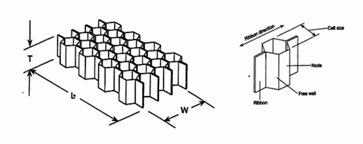
Cell size as shown in Figure 4, is critical since the smaller the cell size the higher the cell density, strength and stiffness. Hence, it was decided to choose a honeycomb core with a cell size of 3 mm the smallest available.
Choosing the Foil Gauge Thickness
The cell wall or foil gauge thickness has to be selected as it affects the density of the honeycomb. The higher foil gauge thickness, the greater the density, hence, a gauge thickness of 0.15 mm was chosen since it was the thickest available.
Choosing the Material for Honeycomb Core
A wide variety of materials is available for the honeycomb core such as aramid fibre, fibre glass, carbon, ceramic, aluminium, steel etc. To arrive at the proper choice of honeycomb core material, first and foremost only commercially available materials were considered and exotic materials such as ceramic or carbon were not considered. To differentiate between metallic cores their behaviour to bending loads was taken as reference.
Two panels one each made of aluminium alloy 5500 and high tensile steel 4340 core were considered. Both these cores had a cell size of 6.35 mm, facial plate of thickness 3 mm, core height of 12.7 mm and both these panels were subjected to three point bending test. From the test results it was reported that the strength to weight ratio at critical load for steel was 1095.7 whereas it was 1211 for aluminium alloy [3]. Since, higher strength to weight ratio means a higher structural strength with reduced mass which is the objective of the study, aluminium alloy was chosen in preference to steel.
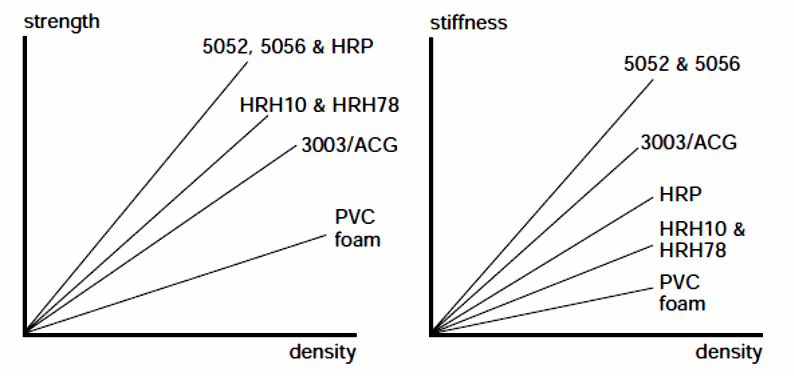
Once aluminium was chosen in preference to steel core, the next step was to select between aluminium, fibre glass and aramid fibre reinforced honeycombs. To do so, their strength and stiffness as a function of cell density was considered as shown in Figure 5 below.
From the above it is clear that aluminium cores (5052 and 5056) have superior strength and stiffness as compared to fibre glass (HRP) and aramid fibre (HRH) reinforced honeycomb cores [4]. Once aluminium core was zeroed in as the candidate choice, the final step was to choose between 5052 & 5056 grade whose properties are given in Table 1.
In the above data x refers to the direction parallel to the ribbon whereas y and z are directions perpendicular to the ribbon. Specifically, y refers to the direction parallel to the core thickness. The point worth noting here is the very small value for Ex, Ez, Gxz and Poisson’s ratio. This value has been assumed as measurements on actual panels tend towards zero. If a zero value was entered into a material model within FEA it would result in stress singularities; to avoid such a scenario theses values were assumed ([5], [6]). From this data it is clear that core made of 5052 is superior to 5056 in crushing, shear, tensile strength and stiffness and hence it is chosen for the panel under study.
Choosing Thickness and Material for the Facial Plate
The thickness of the facial plate, Tf, has to be assumed to optimise core thickness. Hence a 4 mm thick face plate of aluminium alloy 2024T3 was considered for this study.
Determining the Honeycomb Core Thickness
The honeycomb core thickness (Thc) is determined from the panel geometry, materials and applied loads using the optimisation formula [7] given below.
Where Q is the surface load per unit area, L is the panel length, Tf is the facial plate thickness and σf is the compressive yield strength of the facial plate. The variables in the above formula were determined considering the assumptions used for this study as given below.
- Direct floor load is driver weight (Fd) plus ammunition weight (Fa,), taken as 7063.2 N (see Table 2 and Figure 7).
- 20% of the turret load (Ft) is also applied to the floor.
- Area of the floor plate is the entire floor plate not just the modelled section.
Tf = 0.004 m, σf = 270 x 106 N/m2 (for Al 2024T3 alloy)
Substituting all the above parameters into (1) yields:
A honeycomb thickness (Thc) of 12 mm (approximately twice for design safety), with a 4 mm facial plates, was hence selected for the panel.
Modelling of hull with honeycomb panel
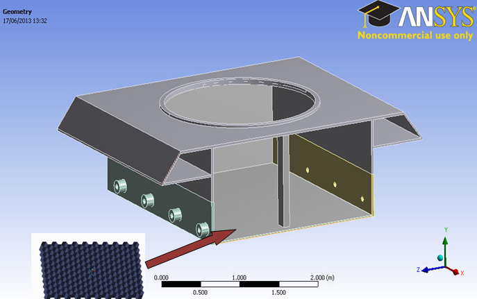
For this study, the main constraint lay in the modelling and analysis of the core. Given the plate dimensions of 4 m x 2 m and 3 mm cell size, the total number of honeycomb cells was around 150,000. For such a large number, direct representation of the geometry is computationally challenging. Hence, to reduce the scope of the model only the most highly loaded central section of the hull was modelled, as shown in Figure 6. Two models one with a honeycomb core and the other with a conventional steel floor plate were modelled for the analysis. The longitudinal, vertical and lateral axes of both hulls were aligned with the global x, y and z axes respectively.
| Properties | 5052 grade | 5056 grade |
|---|---|---|
| Cell size [mm] | 3 | 3 |
| Density [kg/m3] | 130 | 72 |
| Foil gauge thickness [mm] | 0.0762 | 0.0508 |
| Crush strength [MPa] | 9.307 | 5.584 |
| Ey [MPa] | 2414 | 1275 |
| Ex, Ez [MPa] | 10 | 10 |
| µx, µy, µz | 0.01 | 0.01 |
| Gxy [MPa] | 930 | 483 |
| Gyz [MPa] | 372 | 193 |
| Gxz [MPa] | 10 | 10 |
LOAD CASES AND FREE BODY DIAGRAMS
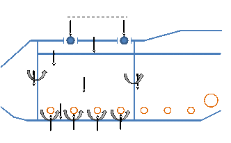
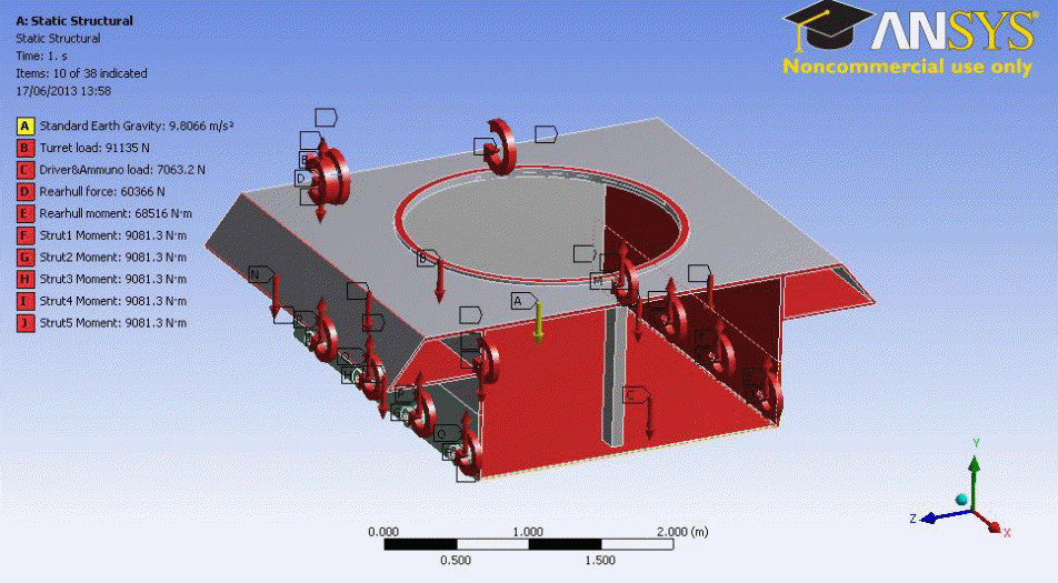
This analysis considers a static load case, with the simulated hull considered to be horizontal and on a level surface. The various loads acting on the two hulls (one with a solid floor plate and the other with a honeycomb floor plate) are listed in Tables 2 and 3; the resultant free body diagram is shown in Figure 7. The philosophy guiding the application of loads assumed the combined weight of the entire vehicle (including sections not simulated) would be equal in magnitude to the combined upwards reaction force resulting from the 14 (eight of which are included in the simulation) wheel/strut stations. The residual forces that would then act between the considering hull sections were then applied to the central, simulated section. For example, the front of the hull, as sectioned, includes no wheel/strut stations, hence its entire weight is applied to the front of the simulated section.
All applied forces act in the vertical direction, and resolve to produce zero net force on the considered section of the hull. No forces are applied in the longitudinal or transverse directions. The values of the direct loads are given in Table 2, and the values of the moment loads are given in Table 3.
The following assumptions were made:
- Gravity load is the weight of the central hull section applied on the C.G. of the hull [8].
- Turret load, applied to the turret ring, consists of the weight of the turret structure, main and secondary armaments, crew members, gun and fire control system, hydraulics and electrical system [8].
- The driver's mass is assumed as 90 kg and the mass of the ammunition is assumed as 15 kg/round [9]; both are applied on the floor plate.
- The fuel load is obtained by multiplying the fuel density (0.832 kg/lit) and the overall volume of the fuel (985 lit); this is applied equally between the hull sponsons [10].
- The frontal armour load is the weight of the nose and glacis plate section that imposes a load and a moment on the face of the central hull section. Similarly the rear hull load is the weight of the rear section including the structure and powerpack applied to the central section.
- Reaction load on each strut is the load due to the self-weight of the tank minus the sprung mass divided equally between the 14 struts. As the two considered hulls have different overall masses (due to the differing floor plates), the individual strut load also varies; specifically, it reduces in the honeycomb case.
Finite element analysis (FEA) of the hull model
ANSYS Workbench version 15 was used to conduct the following analysis. A geometrical model of the considered hull section (indicated in Figure 7) was created, with some level of geometrical simplification, predominantly around the turret ring and wheel stations to eliminate details, which were not significant to the study described here, to allow the model to be efficiently meshed and provide clear results.
Material Properties
The mechanical properties of the structural steel and Al 2024T3 were represented using the linear isotropic material model, with parameters as given in Table 4.
In the honeycomb floor plate case, the facial plates of the honeycomb sandwich were defined using the linear isotropic material model. The macroscopic properties of the honeycomb portion were defined using the linear orthotropic material model; this allows for separate material properties perpendicular and parallel to a given plane to be.
| Applied load | Steel floor plate load [N] | Honeycomb floor plate load [N] |
|---|---|---|
| Gravity load, Fg | 52044.79 | 44023.94 |
| Turret load, Ft | 91134.90 | 91134.90 |
| Driver load, Fd | 882.90 | 882.90 |
| Fuel load, Ff | 8039.49 | 8039.49 |
| Ammunition load, Fa | 6180.30 | 6180.30 |
| Wheel Reaction, Fw | 22703.14 | 21703.90 |
| Front armour load, Ffh | 24000.00 | 24000.00 |
| Rear hull load, Frh | 60366.32 | 54397.82 |
| Systems load, Fs | 75195.21 | 75195.21 |
| Applied load | Steel floor plate [Nm] | Honeycomb floor plate [Nm] |
|---|---|---|
| Wheel Reaction, Mw | – 9081.25 | – 8681.56 |
| Front armour load, Mfh | – 9000 | – 9000 |
| Rear hull load, Mrh | + 68515.77 | + 61741.52 |
| Wheel Reaction 9-10, Mw:9-10 | – 17027.35 | – 16277.92 |
| Wheel Reaction 11-12, Mw:11-12 | – 51082.065 | – 48833.77 |
| Wheel Reaction 13-14, Mw:13-14 | – 85136.77 | – 81389.62 |
| Properties | Structural steel Plate | Aluminium Plate |
|---|---|---|
| Density [kg/m3] | 7850 | 2700 |
| E [MPa ] | 200000 | 70000 |
| µ (Poisson’s ratio) | 0.3 | 0.33 |
| Yield strength [MPa] | 250 | 270 |
| UTS [MPa] | 460 | 429 |
This allowed the core to be treated as a single solid component, the material properties of which (as shown in Table 1) were selected such that its macroscopic behaviour would match the properties of a honeycomb.
Application of Constraints
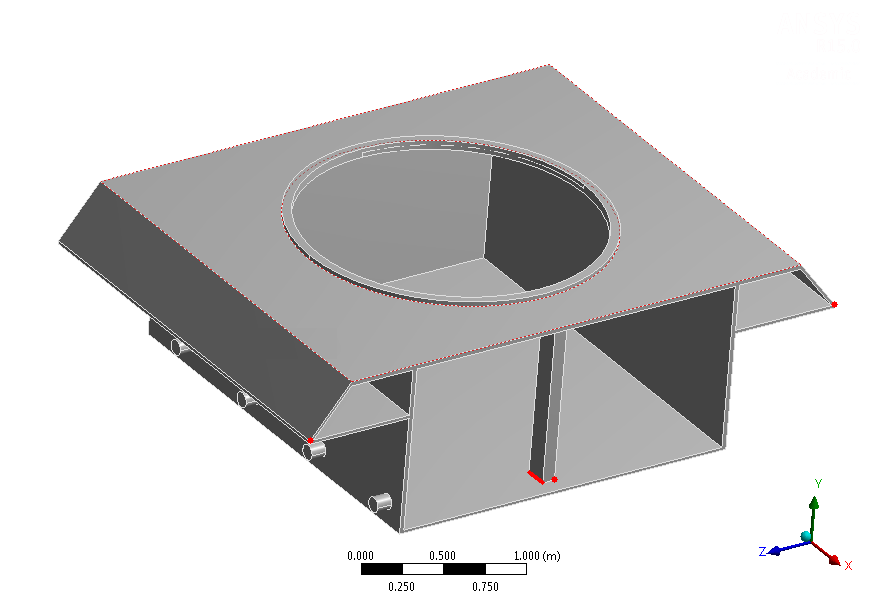
In line with the goals of this investigation, the models were constrained to create the loading resulting from self-weight, in addition to transferring loads/constraints effects to represent the front and back portions of the hull that were omitted as shown in Figure 8. As described above, no net force acts on the hull section, hence the constraints were required only to prevent free body motion and to emulate the effects of the portions of the hull not modelled.
For static structural analysis the model must be constrained in all three axes to prevent free body motion without over constraining the model. This was achieved by constraining the x-displacement (front to back) of the lower right vertex at the front of the vertical pillar to zero, plus the application of elastic supports (of 200 GPa stiffness, longitudinally) at the front and rear surfaces; these prevent longitudinal translation, and two modes of rotation (pitching and turning). In addition it allows for deflection of the constrained surface as described by the specified stiffness, similar to the surface behaviour of the portions of hull not modelled. Displacement of the hull in the z-direction (side to side) was prevented through the constraint of this degree of freedom on a small side-facing edge on the left side at the bottom of the vertical pillar (when viewed from the front). Displacement of the hull in the y-direction (vertical) was achieved through the constraint of this degree of freedom along the upper front vertices at the outer edges of the side sponsons (avoiding the vertical load path between turret ring and wheel stations). The latter two constraints also prevent the final mode of rotation (rolling of the hull).
Constraint locations are indicated in red in Figure 8.
Care was taken to select the above set of constraints such that they did not over constrain the model while still representing the stiffening effect of the front and rear portions of the hull (that were omitted in the model). It is felt that this stiffening effect is closely, but not perfectly, approximated. This is because the actual front and rear hull portions would provide some vertical and lateral support to the centre section (which would act as shear loads at the sectioned surfaces), although none were included in this model (the elastic supports do not prevent sliding parallel to the surface). This is not felt to be significant as the geometry of the end sections of the hull is comparatively stiff in the longitudinal direction, relative to the vertical and lateral directions.
Applying Forces and Moments
The forces and moments as shown in the free body diagram were applied on the hull model as shown in Figure 9. Arrows denote direct force loads, circular arrows denote moment loads and red surfaces indicate the surfaces to which load are applied.
These were applied as combined direct and moment loads at the wheel stations and front and rear section surfaces (applying the weights and moment results from the omitted sections), and surface loads (floor, fuel and turret loads), see Tables 2 and 3 for force and moment magnitudes, respectively. Gravity load is distributed throughout the FE model.
Meshing
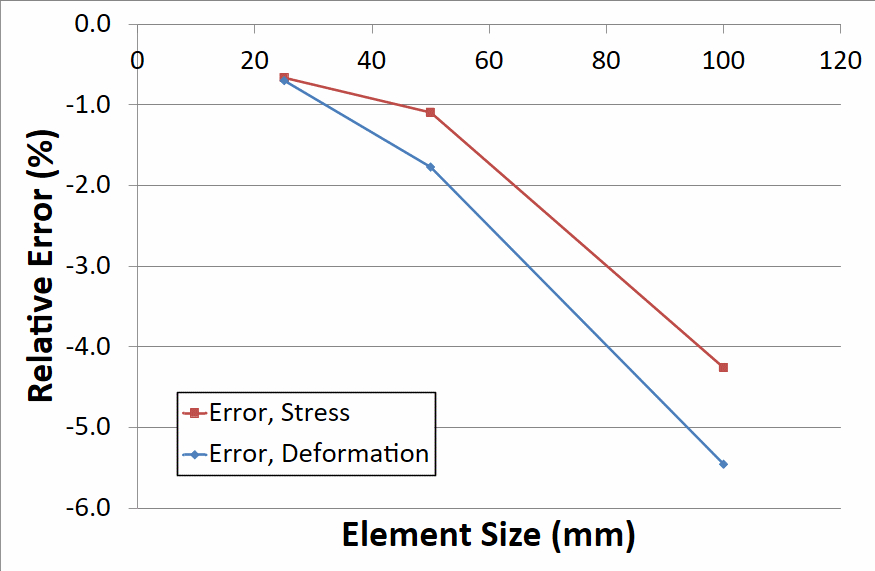
As this study was conducted based on simulation alone, no experimental data was available for comparison/validation. Accordingly, it was necessary to ensure that discretisation error (due to the applied mesh) was small, by reducing element size until error was insensitive to further changes to element size. This this would allow errors due to the finite element model to be ignored. Discretisation error was approximated by conducting a series of analyses of the solid hull; between each analysis, element size was halved. When loaded as described above; relative error between successive sets of results was then determined. Specifically, peak values of both von Mises stress and total deformation were compared between successive sets of results (in each case there were observed to stay in the same location). A target of relative error of less than 1% was set for both values, and an initial element size of 100 mm was selected. The results of the sensitivity analysis are plotted in Figure 10.
Relative error of both peak von Mises stress and peak total deformation reduced below 1% for an element size of 25 mm. No stress singularities were observed (for example in corners of the model) and peak stresses/deformations consistently occurred in the same locations, hence it was felt that the model was well constrained. (Peak stress was observed at the top surface at the front of the turret ring, and peak deformation was observed at/near the front pillar—vertical deflection was the dominant component.)
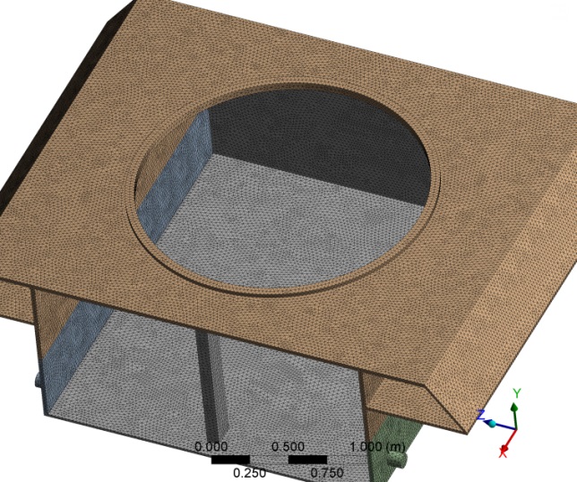
Accordingly, an element size of 25 mm was selected for use as the basis of the analysis presented here. The resulting mesh for the steel floor plate hull is given in Figure 11.
RESULTS
Two sets of results were obtained during post processing using results probes; von Mises stress and total deformation (both hull types). Von Mises stresses are an important indicator of load intensity within the considered metals, and deformation is a summation of strain, hence an effective indicator of comparative overall hull stiffness.
Stress and Deformation for Hull with Steel Floor Plate
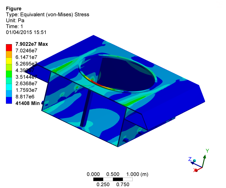
The stress and deformation of the hull with steel floor plate are shown in Figure 12 and 13 respectively. Maximum stress occurs near the turret bearing, wheel struts and the intersection between the top and side plates. The highest deformation occurred along the centre line near the front edge of the hull top and floor plates.
Stress and Deformation for Hull with Honeycomb Floor Plate
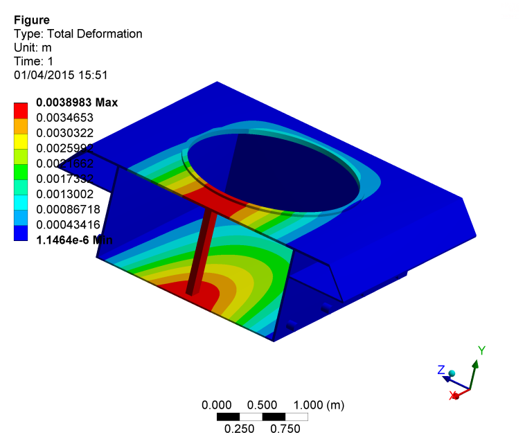
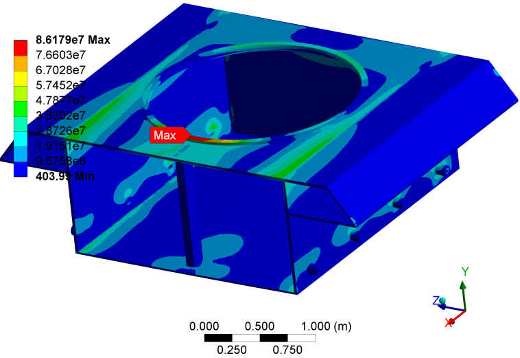
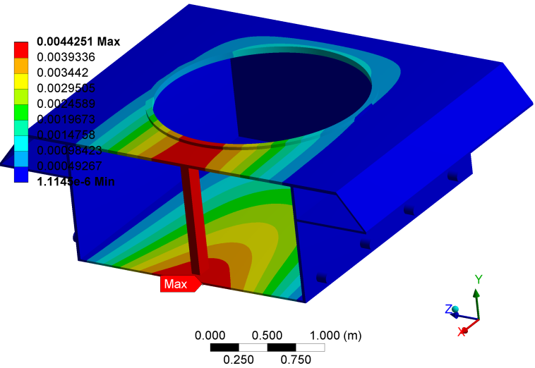
The stress and deformation of the steel hull with honeycomb floor plate are shown in Figure 14 and 15 respectively. For the hull with honeycomb floor plate, both higher stresses and deflections were observed as compared to the steel floor case. The highest deformation occurred along the centre line near the front edge of the hull top and floor plates.
The consolidated stress and deformation results are given in Table 5 and 6 respectively.
| Location | Stress [MPa] | % variation | |
|---|---|---|---|
| Steel | HC | ||
| Top plate | 44.61 | 46.94 | 5.223 |
| Turret bearing | 79.02 | 86.18 | 9.061 |
| Side plate | 51.75 | 47.64 | -7.942 |
| Floor plate | 31.20 | 41.62 | 33.397 |
| Vertical stiffener | 33.18 | 32.59 | -1.778 |
| Horizontal stiffener | 15.95 | 14.63 | -8.276 |
| Location | Def. [mm] | % variation | |
|---|---|---|---|
| Steel | HC | ||
| Top plate (y) | 3.820 | 4.271 | 11.806 |
| Turret bearing (y) | 3.637 | 4.126 | 13.445 |
| Side plate (z) | 0.275 | 0.223 | -18.909 |
| Floor plate (y) | 3.898 | 4.425 | 13.520 |
| Vertical stiffener (y) | 3.830 | 4.231 | 10.470 |
| Horizontal stiffener (x) | 0.391 | 0.441 | 12.788 |
Discussion
From the results listed in Tables 5 and 6 it is observed that the stress and deformation in the hull are comparable for both cases, with the observation that the honeycomb case generally showed greater deflections (~10–12%) and higher stresses than the steel floor case. The greatest increase in stress is seen at the outer edge of the floor panel, where the honeycomb floor model experiences a 33.4% increase in von Mises stress near the front edge. This agrees with expectations, as the honeycomb floor panel would be expected to deflect further than the steel floor panel under an equivalent load as it is less stiff. Material behaviour is still within the linear elastic regime, hence greater deformation results in higher stresses in the remaining steel components. The reduced support provided by the less stiff honeycomb floor panel lowers the compressive load (and hence stress) in the vertical stiffener, as reported in Table 5.
The exception to this is the reduced stress developed in the side plates of the honeycomb case (and horizontal stiffener, due to the applied load from the rear of the hull), due to the decreased wheel reaction force—resulting from reduced overall vehicle weight.
Honeycomb thickness could be increased to offset this reduced stiffness (see Figure 16); Figure 16 describes a generic example of honeycomb structural effectiveness when compared with a solid sheet of metal (aluminium of thickness 0.81 mm, in the referenced examples [2,5]). This solid sheet metal is compared to two sandwiches whose facial panels are each half the thickness of the initial sheet, and bonding a honeycomb core between them. In bending the thickest of the two sandwich panels is 37 times stiffer and more than nine times stronger than the aluminium sheet; weight increases 6%, but panel thickness increases by a factor of four.
A thicker panel incorporated in the present study would reduce the stress and deflection considerably, as well as result in better protection against mine blast. However, this was not investigated in the presented study as the reported stress levels do not affect the integrity of the structure since the design limit for the material is 210 MPa.
Indeed a usage study would need to be conducted if any significant change were made. An increase in floor panel thickness would alter one or more of the following, each of which being critical aspects of MBT design: ground clearance, internal height of crew volume, overall vehicle height.
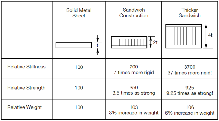
Since the purpose of this study is to optimise weight of the hull the thinner panel design was retained; the results of this investigation validate this as they indicate that strength and stiffness parity is not required. Nevertheless, these types of thicker honeycomb panels could be used as add-on armours below a thinner honeycomb floor plate outside the tank which is a future scope of investigation.
Both models exhibit large deflections centred on the vertical stiffener and the front of the turret ring, which occurs due to the proximity of the turret weight force and the section surface at the front of the considered hull portion (hull roof and floor being linked by the vertical stiffener). At the sectioned surface, an elastic support was applied which provides a surface stiffness perpendicular to the section surface (i.e. in the forwards-backwards direction relative to the hull) but no restraining force in a parallel direction to the surface. Crucially, this means that the front of the hull section is vertically unsupported at an open section near a large vertical load, causing it to be less stiff than it would be in reality—this results in the large deflections observed. However while the absolute defection values may be inaccurate, it is felt that the ratio of the two values provides a useful indicator of the relative stiffnesses of the hulls. This should be addressed in a later study.
Conclusion
The effectiveness of honeycomb structures in MBT construction was investigated via FEA of two hulls, one with a steel floor plate and the other with a honeycomb floor plate. The floor plates, as a part of the hull, were subjected to static structural loading and results compared.
Static von Mises stress and total deformation in the honeycomb floor case were higher than for the steel floor case by 33.4% and 13.52%, respectively, remaining within safe design limits. This supports the view that honeycomb panel structures can be used in MBT hull design without compromising structural integrity, which is the objective of this paper. In addition it was determined that a reduction in overall MBT hull mass of 3.36% can be achieved by replacing the steel floor plate with a honeycomb panel structure. This would improve the mobility of the vehicle and/or allow other benefits such as the addition of other systems to the vehicle to enhance either firepower or protection.
Although honeycomb panel structures offer a promising future in MBT construction they pose two main challenges namely integration and strength. Firstly, MBT hull structures are arc welded; this would reduce the strength of honeycomb panels if they were to be heated (such panels are bonded together by epoxy adhesive, which lose their strength above 180oC). This would pose an integration challenge and may require other means of assembly. Secondly, the bottom facial plate will be exposed to rough terrain during usage causing localised loading, potentially reducing the fatigue strength of the structure, which also needs detailed investigation. In addition, the modelling of a full-length hull section is recommended to eliminate the influence of section end effects and constraints.
In summary, honeycomb structural panels can potentially be incorporated into MBT hulls provided certain key challenges such as integration and usage in service are first addressed.
NOTATIONS
A Area of the floor plate in m2
E Young’s modulus of the material in MPa
Ffloor Load on the floor plate in N
Fturret Load on the turret ring in N
G Shear modulus of the material in MPa
L Length of the floor plate in m
q Total load on the floor plate in N
Q Load per unit area on the floor plate in N/m2
Tf Thickness of the facial plate in m
Thc Thickness of the honeycomb core in m
µ Poisson’s ratio of the material
σf Compressive strength of the facial plate in N/m2
BIOGRAPHIES
Mr A. Hafeezur Rahman has completed his masters MSc (MVT) from Cranfield University, UK in 2013 and is currently working as a Scientist D in DRDO, India.Email: rahmanhafiz@rediffmail.com.
Dr Mike Gibson completed bachelor and doctorate degrees in engineering from Cranfield University, and is currently a Research Fellow in the Centre for Simulation and Analytics, Cranfield University, Defence Academy of the United Kingdom, Shrivenham, SN6 8LA, UK. Email: m.c.gibson@cranfield.ac.uk.
References
[1] T.W. Terry, S.R. Jackson, C.E.S. Ryley, B.E. Jones, and P.J.H. Wormell, Fighting vehicles, London: Brassey’s, 1991.
[2] J. Kindinger, Light Weight Structural Cores [Internet].2013. Available from: http://home.engineering.iastate.edu.
[3] K. Kantha Rao, K. Jayathirtha Rao, A.G. Sarwade, M. Sarath Chandra, “Strength Analysis on Honeycomb Sandwich Panels of Different Materials”, International Journal of Engineering Research and Applications [Internet], 2012 June.
[4] Hexweb, Honeycomb Attributes and Properties [Internet], 2013. Available from: http://www.hexcel.com/Resources/DataSheets/Brochure-Data-Sheets/Honeycomb_Attributes_and_Properties.pdf
[5] Hexweb, Honeycomb Sandwich Design Technology [Internet], 2013. Available from: http://www.hexcel.com/Resources/DataSheets/Brochure-Data- Sheets/Honeycomb_Sandwich_Design_Technology.pdf.
[6] Schwingshackl CW, Aglietti GS, Cunningham PR, “Determination of Honeycomb Material Properties: Existing Theories and an Alternative Dynamic Approach”, Journal of Aerospace Engineering [Internet], 2006 July; pp. 177–183. Available from: https://webspace.utexas.edu/jkm343/mikulak.pdf
[7] Zenkert D, An Introduction to Sandwich Construction, 2nd ed, New York: Engineered Materials Advisory Services Limited; 1995.
[8] World of tanks, Leopard 1 [Internet]. 2013. Available from: http://wiki.worldoftanks.com/Leopard_1.
[9] Foss CF, Jane’s Armour and Artillery 2011-2012, 32nd ed, New York: Jane’s Information Group 2011.
[10] Wikipedia, Diesel Density [Internet], 2013. Available from: http://en.wikipedia.org/wiki/Diesel_fuel.
[11] ASM, Structural Steel [Internet], 2013. Available from: http://asm.matweb.com.
[12] ASM, Aluminium 2024T3 [Internet], 2013. Available from: http://asm.matweb.com.