
Volume 18, Number 1, March 2015
Damage Estimation And Assessment Modelling Of Ground Targets In Air-Land Battle Simulations
- 1 Institute for Systems Studies and Analyses (ISSA), Defence Research and Development Organisation (DRDO), Metcalfe House, Delhi 110054, Delhi, India.
Abstract
Abstract: This paper proposes a methodology for the design and development of damage estimation and assessment models based on the weaponeering concepts to estimate and assess the damage caused to ground-based targets from air-borne platforms. These models are used to assess the effectiveness of ground attack weapon systems in an air-land battlefield scenario. A software package called Over Target Requirement Estimation System (OTRES) has been developed based on the proposed methodology which considers a number of factors such as weapons characteristics, target parameters, terrain, target vulnerability, weapon effects, munitions delivery errors, damage criteria, probability of kill, weapon detonation reliability to estimate the damage to a ground target. This estimate is used to generate course of actions and the planner selects one of them by corroborating with other environmental factors, enemy defences and intelligence inputs. The selected course of action (mission plan) is gamed against the perceived threat using the Air Warfare Simulation System (AWSS) test-bed which calculates the attrition to air missions by ground-defence systems deployed to defend a vulnerable area / vulnerable point (VA/VP), and the results are analysed to derive training lessons from the simulator.
Introduction
With rapid advances in technology and increasingly complex defence systems in operation, substantial effort and resources are spent on training for their effective usage. Furthermore, it is not always feasible to replicate the environment under which such systems are deployed and operated. To improve the efficiency, effectiveness, usage and safety of training, organizations and user agencies are investing heavily into developing computer-based training simulators. Modelling and simulation (M&S) is thus becoming the main approach used by defence organizations in support of complex military operations, training and evaluation of existing and proposed defence systems [1,9]. Basic M&S application areas are shown in Figure 1.
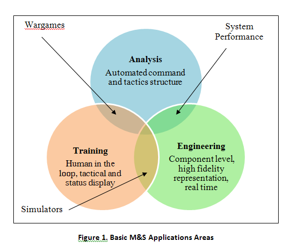
Military simulations, also known formally as wargames, are physical or electronic simulation of military operations designed to explore the effects of warfare or testing strategies or an operational concept without actual combat. Physical simulations as in the forms of sand-table exercises are used extensively for training. With the employment of large-scale computer simulation facilities available, a shift from sand-table exercises to digital battlefields and virtual warfare simulators has taken place [3,10,11]. The main advantages of developing training simulators are their ability to model real world operations and represent human reasoning in various decision-making processes. Human operators undergoing training are important decisions making entity which perceives the environment, evaluates the various alternatives, and decides upon the most appropriate actions to be taken to meet the set training objectives. The design and development of such large scale simulators demands a formal architecture and development of a military simulation framework that is often based upon the needs, goals of training and resolution of the wargames.
To achieve these objectives, an Air Warfare Simulation System (AWSS) has been designed and developed as a framework and test-bed using the Discrete Event System Specification (DEVS) methodology [6,10,12] for creating and simulating several classes of air-land battle scenarios [1,5]. The user can create a number of what-if scenarios and design battlefield experiments on the AWSS virtual battlefield test-bed to simulate various air-land battles.
In such training and analysis systems damage estimation of ground targets is the key component and thus requires development of high resolution models for the same. In this paper, we present a methodology for designing and developing damage estimation and assessment models based on the weaponeering concepts [2,4] to estimate and assess the damage caused to ground-based targets from air-borne platforms and weapons and evaluating their effectiveness in a synthetically generated air-land battlefield scenario.
The paper is organized as follows. In Section 2, we describe the AWSS virtual battlefield test-bed. Section 3 describes damage assessment models for point, area, bridge and building targets based on weaponeering concepts. OTRES software which estimates damage to targets is described in Section 4. Simulation of an air-land battlefield using AWSS in an integrated air defence scenario is described in Section 5 followed by conclusions and scope for future work.
Air warfare simulation system (AWSS)
Design and development of large scale military simulations need to be adaptive to the frequent changes in doctrines, tactics, upgrades in weapon systems capabilities and strategies in warfare. Hence, it becomes imperative to build flexibility and agility in the development of products and processes. An engineering approach to such development is to use an architectural approach that distinguishes between the commonality and variability aspects of development. A thorough analysis and evaluation of the M&S architectures was undertaken before finalising the architectural framework shown in Figure 2.
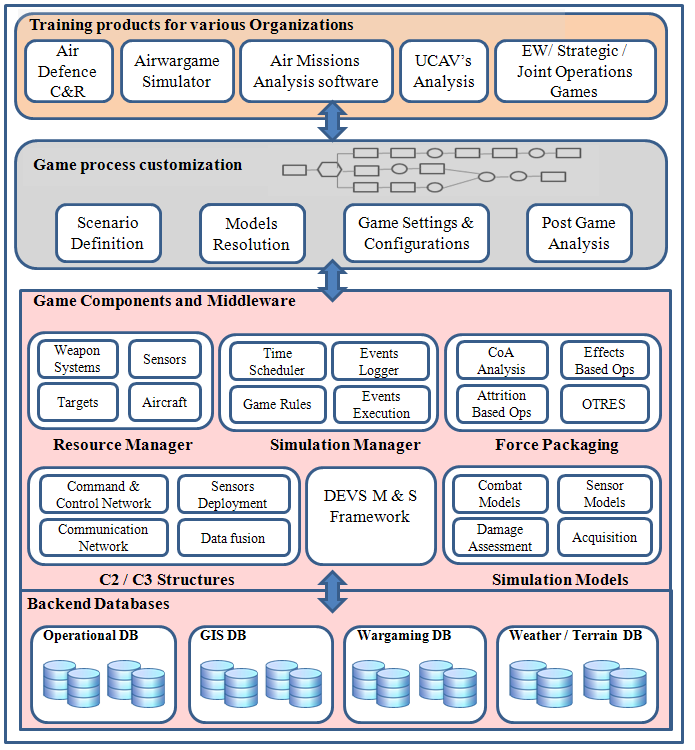
AWSS simulates a wide range of military air operations such as offensive / defensive counter air missions, counter surface force operations, air-defence missions, and combat-support operations between two or more opposing forces [3]to meet the objectives like destruction of a synthetically generated target such as an airfield, vital bridge, refinery, power plant, army installations or other locations of strategic importance. Extensive set of game rules have been developed over the period of time to simulate these operations under different weather and terrain conditions to generate realistic results in a quantitative manner. This system is being used for training and operational analysis and also as a decision-support tool for different echelons of the military planners.
AWSS provides a platform for deployment of resources, weapon target matching, force planning, force execution, damage estimation, damage assessment, quantitative results analysis and displaying reasoning for generating outcomes which is crucial for debriefing and learning purpose. It also computes the attrition rates, statistics of various operations and in-depth history of various events generated during the simulation which helps in analysis and validation of tactics and various operational objectives.
An important component of this system that is used to estimate the damage caused to the ground targets depends on a large number of parameters. Some of the parameters can be determined at planning time whereas parameters that are environment specific, new events generated because of the enemy reaction can only be seen at run-time. These events and the decisions taken thereof, determine the course of action of the simulation and affects the effectiveness of the missions, and the damages caused to the ground target.
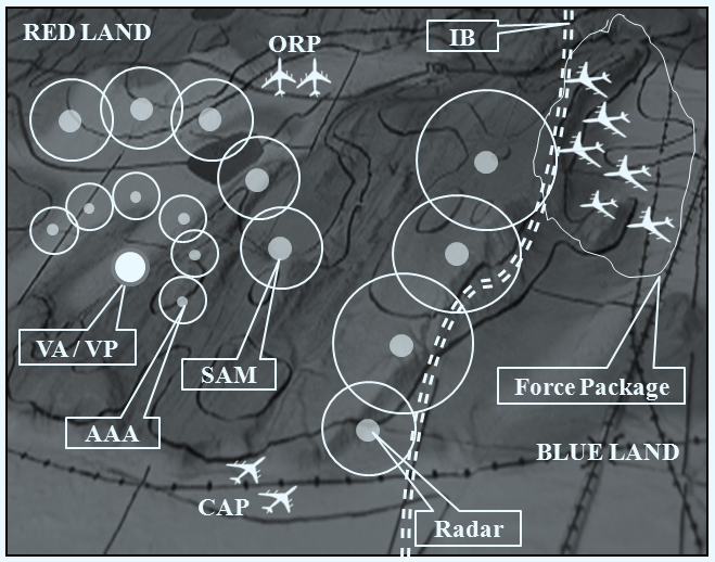
Figure 3 depicts a typical multi-layered air defence scenario. A synthetically generated border is created by an instructor, resources are allotted to the teams and one team is designated as defender and the other as an attacker. The teams deploy their ground and air assets for the protection of their VA/VPs. The attacking team plans air strikes to attack the VA/VPs of the other team. The first and foremost step in this process of planning air strikes is to estimate the number and type of weapons to be launched by the air platforms to nullify the ground targets [7,8]. A methodology for estimating the number of weapons required to cause a specific level of damage to a given VA/VP is described in the following section.
Damage estimation models
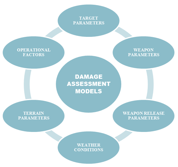
Weaponeering is defined as the process by which the minimum force level and optimum ordnance needed to achieve a desired level and assurance of damage to a target or a critical component, so that enemy war fighting capability is affected, are determined [2]. High-resolution physics based models for depicting the delivery of ground attack weapons from air platforms have been developed using weaponeering concepts. These models help in determining the optimal quantity of a specific type of weapon required to achieve a specific level of damage to ground targets considering weather, terrain, target vulnerability, weapon effectiveness, delivery accuracy, damage criteria, probability of kill, weapon detonation reliability, weapon release conditions and other operational factors. Factors affecting damage estimation models are shown in Figure 4.
Modelling damage estimation process can occur at different levels of resolution. High resolution models employ physics based principles to derive the damages whereas low resolution models may use statistical analysis of the past data to generate the damages caused to target. The choice of the models depends on the resolution of the analysis required. Multi-resolution modelling (MRM) is an important direction of research which uses aggregation and disaggregation techniques for effectively choosing a model for a given resolution [10,12].
3.1 Ground Targets Classification
Ground targets in AWSS are classified as point, area, bridges and buildings based on their size and structural characteristics stored in the target folder.
- Point target: A target of such small dimension that requires the accurate placement of ordnance in order to neutralize or destroy it. Targets such as a tank, an aircraft on ground, ground radar fall in this category.
- Area target: Target that contains multiple target elements uniformly distributed inside a defined area. Examples such as troops, tanks, vehicle convoys fall in this category.
- Bridge: Structures built to span physical obstacles, for the purpose of providing passage over the obstacle. These form an important entity in warfare simulations for logistics and personnel movement and therefore when attacked as a target has a cumulative and lasting impact on the course of actions in a war game.
- Building: Three-dimensional structures such as blast pens, hangars, control rooms fall in this category.
3.2 Damage Model For Point Target
For range direction which is the same direction as the velocity vector of the aircraft delivering the weapons, the accuracy distribution relative to the target is represented by Gaussian normal g(x), and the damage function can be represented by the Carleton damage function c(x) which is similar in shape to the bivariate Gaussian, except that it has value of unity at (0, 0). For Carleton damage function, value of the function itself is of interest, whereas for bivariate distribution, area beneath the function is important [2].
Suppose a single weapon is released against a point target which falls at a distance x = u from the target as shown in Figure 5.The damage caused to the target by a single weapon is the value of damage function at the target, denoted by SSPD1. The location of weapon impact is treated as a random variable, and, based on the analysis of delivery accuracy, can be considered as a normally distributed variable with known statistics.
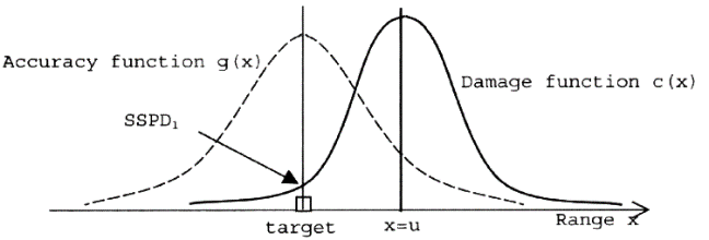
In this work we assume that the weapon accuracy in the range direction is independent from the weapon accuracy in the deflection direction thereby enabling the SSPD in the range and deflection directions to be evaluated independently. Accuracy function g(x) relative to the target is assumed to be normally distributed with mean zero expressed in the form:
whereand REP stands for range error probability value which denotes the weapon system’s precision along the range direction.
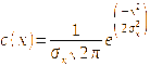
The damage function c(x) along the range direction is also assumed to take the one-dimensional form of the Carleton damage function which is defined as:

where LET is the effective target length and is computed for fragmentation and blast warheads as follows:
- For fragmentation warheads:
where, I is the impact angle of the weapon.
- For blast warheads:
Different random impacts of a weapon against the target produce different values of SSPD from the intersection of the target and damage function.
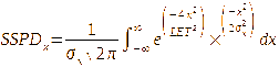
For the range direction:

After substituting the value of (1) and (2) in (3):
Solving this equation:
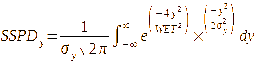
Similarly for the deflection direction:
Solving this equation:
Where WET is effective target width and is computed for fragmentation and blast warheads as follows:
- For fragmentation warhead:

For blast warhead:

The overall SSPD is then obtained by multiplying the individual range and deflection SSPD to obtain:

where is the weapon’s detonation reliability.
If there are n sorties then the total SSPDn is given by:

3.3 Damage Model For An Area Target
For an area target, damage is measured as expected fractional damage (EFD). This is because the target area contains a fixed number of target elements and of primary interest is the fraction of those elements damaged.
The following two cases arise:
- If the weapon lethal area is larger than the area target then the centre of the target is the desired mean point of impact (DMPI) and all the weapons will be aimed at this point.
- When the target area is larger than the weapon lethal area, there is something of a dilemma regarding the selection of aim points in order to get optimum coverage.
The fractional damage when the weapons are spread out would be larger than when they are aimed at a single DMPI. The average SSPD over all of the aim points can be obtained by spreading the single weapon lethal area over the whole of the target—that is, by enlarging the individual weapon lethal area to be equal to the target dimensions. Having done this, all weapons represented by the enlarged lethal area would be aimed at the centre of the target as for the preceding case. Enlarged weapon lethal area dimensions are denoted by LEP and WEP defining the effective pattern, where:
where LA and WA represent target length and width respectively. Fractional damage, FD, is thus defined as:

where FC is the fractional coverage and is defined as the fraction of the area target covered by a rectangular weapon lethal area and PCD is the conditional damage probability inside the rectangular lethal area. For a large number of independent trials, the average value of the damage function at the target will tend towards an expected value and thus expected fractional damage (EFD) would be computed as:
where E (FC) is expected fractional coverage and is obtained by multiplying the expected fractional coverages along the range (E (FR)) and deflection (E (FD)) directions [2]:

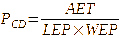
In order to preserve lethality, the conditional probability of damage inside the enlarged lethal area has to be reduced from unity to the following value
where, AET is effective target area and is computed as:

This is the same expression that would apply to the case where the weapon lethal area is greater than the target, expect that for that case PCD =1.
To provide one method for dealing with both cases, the variables LEP and WEP can be calculated from:
Hence, EFD is defined as:

3.4 Damage Model For A Bridge Target
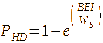
Bridges are an important target in air-land battles and joint warfare operations. Bridges are constructed in many different forms and materials, and their vulnerability to air-launched weapons depends on many factors. The basic approach for bridges is to determine a value of PHD using the bridge effectiveness index (BEI). PHD is defined as probability of damage given a hit. BEI is an empirically derived damage function and can be thought of as an equivalent width over which damage to a particular type of bridge by a specific weapon will occur.BEI is a function of both the weapon type and bridge type. The actual values of BEI are obtained from the various experiments conducted in test ranges and are generally classified, although they are found to be in the range 0–80 ft. PHD value for the bridge can be computed as:
whereWb is bridge width and is defined by:

For BEI method weapon lethal dimensions are set equal to the bridge dimensions:

where LET and WET are given by (4). The overall SSPD can be computed as follows:

3.5 Damage Model For Building Target
Similar to bridges, buildings construction materials and methods vary considerably. Building mean area of effectiveness (MAEBLDG) is used to describe the damage function for the building and it’s the area (in square feet in the ground plane) over which a weapon will damage the building. The actual values of MAEBLDG are obtained from the various experimental trials conducted in test ranges and are generally classified. The method begins by calculating an initial value of LET given by:
If LET is greater than the length of the building (LA, in feet) the equivalent miss distance (EMD, in feet) for the building is computed using:

Otherwise EMD is set to zero.
If the impact angle is 90° then no target shadow of the building height exists, and the shadow length and width(LSH and WSH, in feet) are set to zero. For all other impact angles LSH is computed using:

where HA is the target element height (in feet) and I is the impact angle of the weapon.
The new effective target area is calculated from:
Effective target area is computed using:
AET = [LA + 2 ×EMD] × [WA + 2 ×EMD] + LSH×WA
and WET is computed using: WET = AET / LET
The overall SSPD is computed from:
3.6 Guided Weapon Delivery Accuracy
The accuracy with which guided weapons are delivered depends on the weapon guidance system and is usually considered independent of the aircraft delivering the weapon. Guided weapon accuracies are not subject to ballistic dispersion. Unlike the unguided weapon, which has to be released at the ballistic point in order to hit the target, a guided weapon has a volume in space such that if the weapon is released anywhere within this volume it will reach the target. This volume is referred to as the launch acceptable region (LAR), or basket. For a missile, the LAR is larger and long standoff is possible with such weapons.
For such weapons, the miss distance distributions are not normally distributed. Such distributions have a relatively large number of impacts directly on the target. Hence a revised methodology for these weapons that exhibit a large number of direct hits is considered. To determine how non-Gaussian the data are, one can treat direct hits as having a miss distance of zero in both range and deflection and calculate the mean and standard deviation for all the data. Performing a chi-squared test would then reveal how close our miss distances are to an assumed Gaussian distribution and would result in a relatively poor result, that is, not close to Gaussian. This is because of the large number of hits in the bin are located at the target. If we now remove a few of the direct-hit data points and repeat the test, the results improve because the peak is reduced and the histogram becomes more like that representing a normal distribution. By removing a particular number of direct hits NHIT, the remaining data get as close to Gaussian as they can.
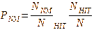
The calculation of SSPD is a little different to that for unguided weapons—PHIT and PNM are used as weighting factors to balance the direct hit and Gaussian miss distribution values of SSPD. An appropriate function takes the form:
whereSSPD1is the value for SSPD computed for unguided weapon.SSPD2is the same as SSPD1 except that the value of REP and DEP is taken as zero, PNM is the probability of near miss and PHIT is probability of hit, such that:
Where NNM is the total number of impacts included in the final Gaussian distribution, NHIT is the number of impacts that had to be removed from the data to form the best normal distribution for the remaining data and N is the total impacts.
Over target requirement estimation system (OTRES)
Based on the models discussed above, the Over Target Requirement Estimation System (OTRES) software has been designed and developed to estimate the number of weapons required to destroy a target with a given assurance level. The weapons are modelled using high-resolution physics-based models and take into account the various parameters that are specific to the weapon selected. However, this estimate is based on the ideal conditions and needs to be subjected to several factors such as weather conditions, ground and terrain conditions, visibility, drag coefficient of the weapon, target acquisition of onboard sensor, enemy air and ground defence, which affect the results and attrition of air and ground assets.
In most of the cases, the target parameters of interest are length and width. However, for point target these dimensions are not required. Weapon characteristics contain information about the drag properties of the weapon, ballistic dispersion, and detonation reliability. Weapon detonation reliability factor is used in weapon effectiveness computation to allow for the possibility that the weapon does not detonate correctly. Aircraft release parameters provide inputs to high-fidelity trajectory models for the computation of trajectory details. Weapon delivery accuracy is given by range error probability (REP) and deflection error probability (DEP).
OTRES software takes several input parameters such as target specifications (type, length, width and height), weapon specifications (warhead type, drag constant, ballistic dispersion, and reliability), weapon release conditions (airspeed, dive angle, release height, and number of weapons dropped) and weapon delivery accuracy (REP and DEP).The output parameters obtained as shown in Figure 6 are trajectory details (vertical impact velocity, horizontal impact velocity, impact angle, time of flight, slant range and ground range) and damage estimates (SSPD / EFD range, SSPD / EFD deflection, and combined SSPD / EFD).
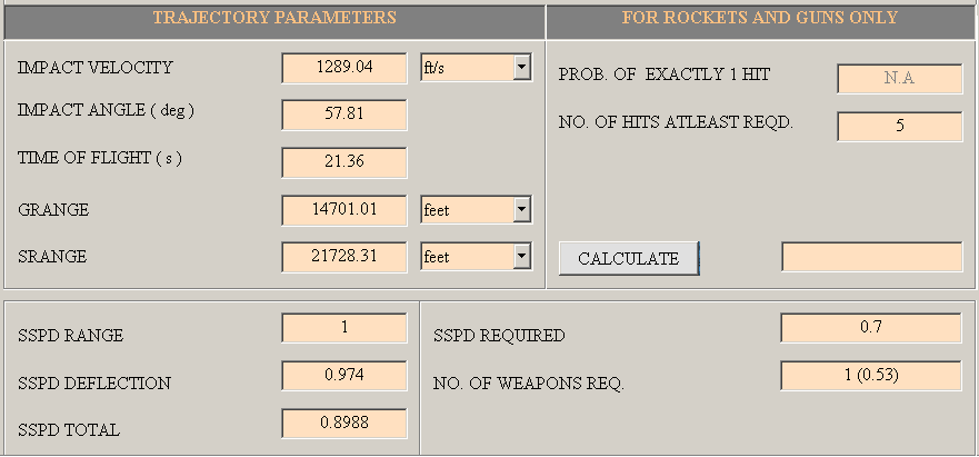
Example: For the following inputs as target specifications (type = area target, length = 200 ft, width = 80 ft), weapon specifications (warhead type = fragmentation, drag constant = 0.005, ballistic dispersion = 5 mils, reliability = 0.68), weapon release conditions (airspeed = 500 ft/sec, dive angle = 30 deg, release height = 3500 ft, number of weapons dropped = 1),output parameters obtained using OTRES are trajectory parameters (vertical impact velocity = 620ft/s, horizontal impact velocity = 710 ft/s, impact angle = 42 deg, time of flight = 6.81 sec, slant range = 6000 ft, and ground range = 5000 ft), and damage estimates (EFD range = 0.72, EFD deflection = 0.97 and combined EFD = 0.22).
Simulation using AWSS test-bed
In order to evaluate the effectiveness of the air campaigns / missions and performance of weapons systems a synthetic battlefield was created on AWSS test-bed.
The deployment patterns of the various ground air-defence systems, air-support (defensive) operations from the air assets such as Combat Air Patrolling (CAP), Operations Readiness Platform (ORP), the on-board weapon systems for EW and land forces deployment are considered as part of the air defence scenario that retaliate against the air missions. Deployment of radars and other sensors in the area provide the common operational picture of the battlefield to the commander on ground. Based on the situational assessment of the battlefield the commander provides the necessary instructions to the pilots of the air missions. High resolution models of the various sensors are used to generate performance curves and the detection probability of the enemy air missions. Each of the events such as detection of enemy aircraft by sensors, engagement with CAP / ORP / SAM / AAA, target acquisition, is subjected to statistical distribution functions that generate the events in the simulation framework. Air defence units deployed for the protection of VA / VPs are:
- One battery of surface-to-air missile (SAM) is deployed around each target with performance details as:
- Min range (km): 1
- Max range(km): 7
- Min altitude(km): 0.2
- Max altitude(km): 4
- Tracking radar range(km): 30
- Kill probability with ECM: 0.50
- Kill probability without ECM: 0.40
- Two batteries of anti-aircraft artillery (AAA)is deployed around each target with performance details as::
- Effective kill range: 2
- Effective kill height: 1.5
- Kill probability: 0.002
Some of the important factors affecting damage models taken during the estimation are shown in Tables 1–4. Table 1 describes the physical characteristics of target types, Table 2 describes the weather parameters, Tables 3 and 4 describe weapon and aircraft release parameters, and Table 5 describes the cluster bomb characteristics.
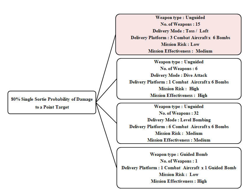
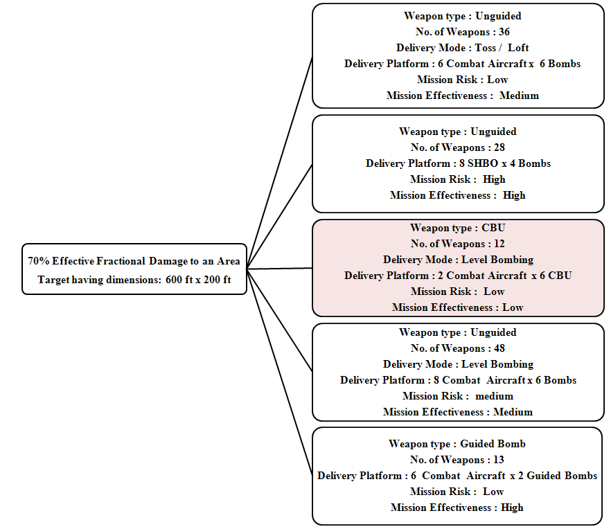
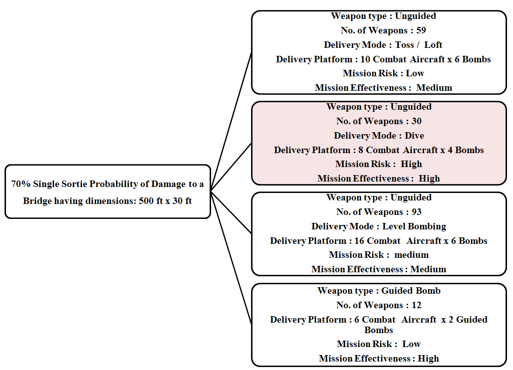
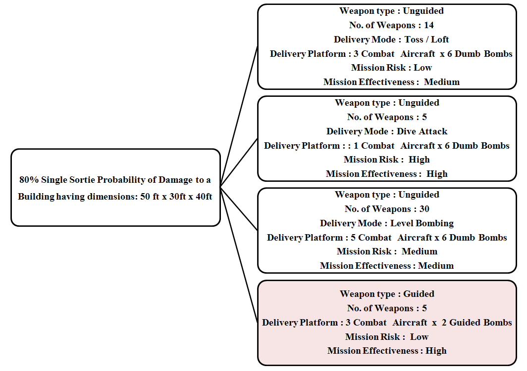
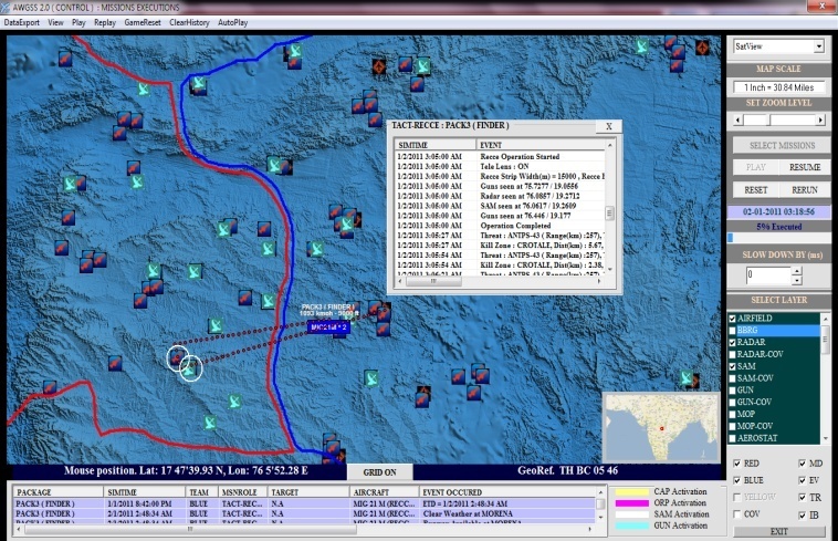
The weapons effectiveness (as the damage to the target and effects produced) as estimated by the OTRES leads to the generation of the various courses of action (COA) along with the Mission Risks and Mission Effectiveness as a cost-benefit measure to the planner. For instance, COA generated for a point target is shown in Figure 7. The planner then chooses a specific course of action which is then gamed on the AWSS test-bed for evaluating its effectiveness. A statistical analysis of the results is obtained and the planner visualizes his missions as he flies through the synthetic terrain, enemy defences, delivers weapons on the target and returns back to base. Similar results for the other targets are summarized in Figures 8, 9 and 10. Figure 11 shows the missions simulation using AWSS test-bed. Table 6 shows the descriptive statistics of the attrition summary because of air defence (AD) and ground defence (GD).
Conclusions
In this paper, we present a methodology for design and development of damage computation models based on the weaponeering concepts to estimate and assess the damage caused to ground-based targets from air-borne platforms.
The proposed architectural framework of AWSS test-bed helps in creating scenarios to design battlefield experiments to obtain a quantitative measure of the damages caused to ground and air borne targets. The OTRES software based on the proposed methodology has been successfully utilized in AWSS for estimating the weapons’ effectiveness in destroying ground targets. This provides valuable inputs to the decision maker (planner) to identify and choose an appropriate COA in the light of the situation posed. The decision taken by the planner is then analyzed using AWSS so that valuable training lessons can be drawn from it. Models developed based on this methodology gave realistic results when used in field training and deployment of the system and also proved to be an important mean for military systems analysis problems that are often posed as a pre-requisite to large scale acquisition, strategic, operational, and tactical decisions in the military circles.
The OTRES approach for modelling damage estimates and assessment are based on the conventional approaches of hard-kill to targets, and may not always be suitable to model the soft-kills and effects-based operations that are necessary in modelling net-centric warfare and strategic games. We are presently working towards including the effects based analysis and estimates as part of the OTRES system.
Acknowledgement
The author wishes to thank Mr Babloo Saha and Ms. Rekha Rani, scientists at ISSA, for their efforts in implementing the models in the AWSS software.
| Target Type | Length (feet) | Width (feet) | Height (feet) | Terrain |
|---|---|---|---|---|
| Point | - | - | - | Hill Peak |
| Area | 600 | 200 | - | Farmland |
| Bridge | 656 | 66 | - | Vegetation |
| Building | 50 | 30 | 40 | Vegetation |
| Clouds | High Level |
|---|---|
| Visibility | Haze (2-6kms) |
| Storm | No |
| Wind | 20 knots / 60 deg |
| Weapon Type | Delivery Mode | REP (ft) | DEP (ft) |
|---|---|---|---|
| Unguided | Toss / Loft | 57.3 | 57.3 |
| Unguided | Dive | 28.65 | 28.65 |
| Guided | – | 20.27 | 15.57 |
| Cluster Bomb | Dive | 170 | 150 |
| Weapon Type | Target Type | Delivery Mode | Height (ft) | Speed (ft/sec) | Dive Angle (°) | Reliability |
|---|---|---|---|---|---|---|
| Unguided | Point | Toss / Loft | 3000 | 760 | 30 | 0.94 |
| Unguided | Bridge | Dive | 3000 | 928 | 30 | 0.95 |
| Guided | Building | - | 12000 | 550 | 45 | 0.68 |
| Cluster Bomb | Area | Dive | 1000 | 928 | 0 | - |
| Number of Submunitions | 202 |
|---|---|
| Dispenser Reliability | 0.8 |
| Submunition Reliability | 0.93 |
| Functioning Time(s) | 1.6 |
| Ballistic Dispersion (mils) | 10.2 |
| Dispenser Spin Rate (rpm) | 5 |
| Dispenser Drag Constant | 0.2 |
| Submunition Drag Constant | 0.15 |
| Total Attrition | Case (i) | Case (ii) | Case (iii) | Case (iv) | ||||
|---|---|---|---|---|---|---|---|---|
| AD | GD | AD | GD | AD | GD | AD | GD | |
| Mean | 0.3 | 0.4 | 0.5 | 0.8 | 0.6 | 0.6 | 0.2 | 0.3 |
| Standard Error | 0.15 | 0.16 | 0.17 | 0.25 | 0.31 | 0.16 | 0.13 | 0.15 |
| Median | 0 | 0 | 0.5 | 1 | 0 | 1 | 0 | 0 |
| Mode | 0 | 0 | 0 | 1 | 0 | 1 | 0 | 0 |
| Standard Deviation | 0.48 | 0.52 | 0.53 | 0.79 | 0.97 | 0.52 | 0.42 | 0.48 |
| Sample Variance | 0.23 | 0.27 | 0.28 | 0.62 | 0.93 | 0.27 | 0.18 | 0.23 |
| Kurtosis | –1.22 | –2.28 | –2.57 | –1.07 | –1.22 | –2.28 | 1.41 | –1.22 |
| Skewness | 1.04 | 0.48 | 0 | 0.41 | 1.04 | –0.48 | 1.78 | 1.04 |
| Range | 1 | 1 | 1 | 2 | 2 | 1 | 1 | 1 |
| Minimum | 0 | 0 | 0 | 0 | 0 | 0 | 0 | 0 |
| Maximum | 1 | 1 | 1 | 2 | 2 | 1 | 1 | 1 |
| Sum | 3 | 4 | 5 | 8 | 6 | 6 | 2 | 3 |
| Count | 10 | 10 | 10 | 10 | 10 | 10 | 10 | 10 |
| Largest(1) | 1 | 1 | 1 | 2 | 2 | 1 | 1 | 1 |
| Smallest(1) | 0 | 0 | 0 | 0 | 0 | 0 | 0 | 0 |
| Confidence Level (95.0%) | 0.35 | 0.37 | 0.38 | 0.56 | 0.69 | 0.37 | 0.3 | 0.35 |
| SSPD / EFD Planned | 0.8 | 0.7 | 0.7 | 0.8 | ||||
| SSPD / EFD Achieved | 0.7 | 0.35 | 0.57 | 0.84 |
References
[1] Basic Doctrine of the Indian Air Force, 2012 (http://www.scribd.com/doc/109721067/Basic-Doctrine-of-Indian-Air-Force-2012-PDF).
[2] M.R. Driels, Weaponeering Conventional Weapon System Effectiveness, AIAA Education Series, Virginia, 2004.
[3] D. Vijay Rao, The Design of Air Warfare Simulation System, Technical Report, Institute for Systems Studies and Analyses, 2011.
[4] D. Vijay Rao and K. Jasleen, “A Fuzzy Rule-based Approach to Design Game Rules in a Mission Planning and Evaluation System”, 6th IFIP Conference on Artificial Intelligence Applications and Innovations, H. Papadopoulos and A.S. Andreou, Cyprus Springer, October 2010.
[5] A. Law andW. Kelton, Simulation Modelling and Analysis, McGraw-Hill, New York, 1991.
[6] J. Banks, Discrete Event System Simulation, Prentice Hall of India, 2002.
[7] C.C. Travers, Optimizing Aim Points for Multiple GPS Weapons Released Against a Single Target, MS Thesis, Naval Postgraduate School, Monterey, CA, September 2002.
[8] R. Ball, The Fundamentals of Aircraft Combat Survivability Analysis and Design, AIAA Education Series, AIAA, Reston, 2003.
[9] J.T. Dockery and A.E.R. Woodcock (eds), The Military Landscape: Mathematical Models of Combat, Woodhead Publishing, Cambridge, England, 1993.
[10] A. Tolk, Engineering Principles of Combat Modeling and Distributed Simulation, John Wiley and Sons, New Jersey, USA, 2012.
[11] N.K. Jaiswal, Military Operations Research: Quantitative Decision Making, Kluwer Academic Publishers, USA, 1997.
[12] S. Mittal and J.L. Risco Martin, Netcentric System of Systems Engineering with DEVS Unified Process, CRC Press, USA, 2013.