
Volume 17, Number 1, March 2014
Mitigation Of Fragment Spall Induced By Explosive Loading In High Performance Fragment Generators
Abstract
A typical pre-fragmented warhead uses explosive energy to launch fragments. On initiation of the explosive, detonation waves impinge on the fragments and thereby generate shock waves in the fragment material. As the shock wave reaches the fragment exposed surface, the compressive stress wave is reflected back as a rarefaction wave. At the same time, the rarefaction wave generated from detonation side enters in the fragment. The interaction of these rarefaction waves induces intense tensile stresses resulting in fragment spall. Several researchers have attempted to reduce fragment spall by reducing explosive charge to fragment metal mass ratio (C/M ≤ 0.5) or by altering the explosive initiation location or by provision of shock attenuation material between explosive and fragments or by capping individual fragments. The authors have evolved an innovative solution to mitigate spall by the provision of a composite layer on the fragment exposed surface in the design of high-performance fragment generator (FG) warheads. Its performance is demonstrated experimentally in FG warhead designs having C/M ratios of 1 and 2. The soft recovered fragments in the cone angle of 300 did not show any spall in the case of fragments covered with the composite layer, whereas, the conventional design of (uncovered) fragment did spall.
Introduction
In a fragment generator (FG) warhead configuration, a fragmenting disc is manufactured using premade fragments, which is integrated into one end of a cylindrical casing filled with an explosive charge, with an initiation system at the other end [1–4]. On detonation of the explosive, fragments are accelerated by the detonation shock front and by forces exerted by the casing expansion caused by generation of gaseous products following detonation.
The spall failure occurs in condensed matter loaded with enough dynamic tension for a sufficient time. This generally happens in case of impulsive loading, where rarefaction waves interact. The common examples of such loading are projectile impact and explosion. In the case of explosive loading, the detonation front, when it impinges on the material in contact, induces a compressive shock wave in the material. This highly compressed shock wave reaches the next surface of the material and is reflected back as a rarefaction wave. At the same time, due to rarefaction of the detonation front, one more rarefaction wave travels in the material. Both these rarefaction waves travel in opposite directions in the material. Their interaction generates extreme tensile stresses in the interior of the material, which causes microscopic size fracture in the interior of the fragment. Coalescence of these microscopic fractures and momentum transfer due to interaction of the waves separates a portion of fragment material. If the tensile stresses exceed the dynamic tensile strength (known as spall strength) of the material, it fails and this failure extends over a region where all the tensile stresses exceed the spall strength [5,6]. The failed portion of the material flies off in the form of a chip or scab.
The problem of fragment spall mitigation has been addressed by number of researchers. Walter and Zukas [7] suggested a few millimetres of gap between the explosive and fragmenting disc. A US Patent [8] describes a shock attenuator disposed between the fragments and explosive. Anderson [9] reported test results based on experiments conducted with aluminium-capped tungsten alloy fragments. This method suppressed the spall but failed to prevent fracture along the fragment centre line. Yet another concept of backward burning is reported by Lloyd [10]. The problem of fragment spall is observed to be pertinent, when the ratio of the explosive charge mass to fragmenting disc metal mass (C/M ratio) exceeds a value of 0.5 [7].
The reported methods prevent fragment spall either by reducing shock intensity or by providing a gap between explosive and fragment material or by disposing shock attenuating material or by the detonation wave front moving away from the material (backward burning). These methods reduce launch acceleration, which results in low fragment velocity. An alternate method of reduced explosive charge mass compared to accelerating fragment material mass, also results in low velocities. Adding an aluminium cap on individual fragments keeps the launch accelerations similar to those without capped fragments, although lateral rarefaction split the fragments.
Generally, FG configuration design calls for C/M ratio greater than 0.5 leading to fragment spall. The authors have also observed tungsten alloy fragment spall in FG configurations with C/M ratio of 1. Mass of the spalled fragment is lower than its original mass, which reduces its lethality. Hence, the fragment spall issue needs to be addressed.
To mitigate spall without reducing the impinging intensity of shock pulse, an innovative solution is devised and its performance is demonstrated experimentally. A composite layer on the exposed surface of premade tungsten alloy fragments in the fragmenting disc is provided. Its performance in FG configurations having C/M ratios 1 and 2 have been carried out. It is observed that there is no fragment spall and lateral fracture in the cone angle of 30°. The paper presents the details of composite layer and test results.
Fragment Generator Configurations
The configurations of FG warhead test evaluated are shown in Figure 1. Configurations 1 and 2 had a C/M) ratio of 1; whereas, Configuration 3 had a C/M ratio of 2. The fragmenting disc in Configuration 1 was made without any spall mitigation layer on the exposed surface of fragments. The disc was made by laying fragments on 2 mm thick aluminum alloy disc with resin. In Configurations 2 and 3 the fragment exposed surface was covered with a composite layer made of iron powder impregnated resin layer of 2 mm thick, followed by 2 mm thick aluminum alloy disc. The composition of resin layer was prepared by mixing resin, hardener and iron powder in the ratio of 220:20:380 by mass. Total 97 premade cubical fragments of 6 mm tungsten alloy having density 18 g/cc were used in all the configurations test evaluated. The fragments were manufactured by powder metallurgy having composition of tungsten 95%, nickel 3.5% and iron 1.5% by mass. The casing was made of 6 mm thick aluminum alloy and explosive used was HMX/TNT (70/30). The explosive charge diameter was Ø 71 mm. The explosive charge length in Configurations 1 and 2 was 57 mm. Configuration 3 was had explosive charge length of 114 mm. RDX/Wax (95/5) booster (Ø 20 mm x length 10 mm) and an electrical detonator provided in the FG warhead assembly for initiation.
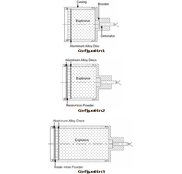
In the design of FG warheads, the fragments originating from the central portion of the fragment disc covering the central seven tenths of the explosive charge radius are considered to be the most effective for lethality. The fragments originating from the rest of the area of the fragmenting disc disperse significantly in their direction and also have low velocity due to edge effects [11]. The concentrated effective fragment beam for the experimented configurations was around 15° full cone.
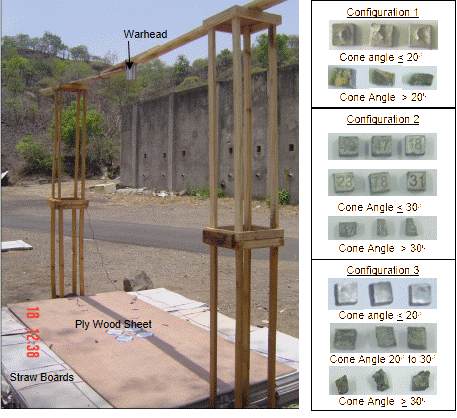
The trial layout and the recovered fragments after the trails are shown in Figure 2. The FG was placed at a height of 2.5m above the ground. Straw boards having sufficient thickness were kept on the ground for soft recovery of the fragments. A sheet of plywood was kept above the straw boards to record fragment dispersion angle.
Results and discussions
The trials in identical set up were conducted for all the configurations. The recovered fragments in different cone angles are shown in Figure 2. In Configuration 1, fragment spall was observed in the central cone of 20° and broken pieces of fragment were observed in the cone greater than 20°. In Configurations 2 and 3, no spall in fragments was observed up to 30° cone angle. Further, it is observed that, in the case of Configuration 3, the recovered fragments between 20° and 30° were slightly distorted. This is likely to be due to the higher quantity of explosive compared to fragment metal mass—that is, C/M ratio of 2. The fragments recovered beyond 20° in Configuration 1 and beyond 30° in Configurations 2 and 3 were found to be broken into a number of pieces, which may be due to lateral rarefaction waves [9].
In Configuration 1, fragments were laid with resin on aluminum alloy disc, and the fragment outer surface is exposed to air. The fragment spall is observed within 20° cone angle as shown in Figure 2. The fragments beyond 20° are observed to be broken due to excessive deformation and interaction between rarefaction waves, including from lateral directions. The impedance of air is significantly lower than the impedance of the tungsten alloy fragment. As the shock wave in the fragment comes in contact with low impedance medium of air, it generates a high-strength rarefaction wave in the fragment, resulting spall (as discussed in the introduction).
In Configurations 2 and 3, the fragment matrix was covered with a composite layer of iron powder mixed resin as well as an aluminum alloy disc. The iron powder mixed resin layer was in intimate contact with exposed surface of fragments, which also ensures intimate contact with a range of sizes and shapes due to manufacturing tolerances of the fragment and the aluminum alloy disc. As the shock wave reaches the fragment and iron mixed resin interface, comparatively low-intensity rarefaction waves are reflected in the fragment compared to the case where the fragment surface is exposed to air—consequently, it dissipates energy. Further, the shock passing through the iron powder mixed resin layer is transmitted to the outer aluminum disc and subsequently to air. Thus, at all these interfaces between materials, two shock waves are generated, which move in opposite directions. The provision of the composite layer reduces the intensity of rarefaction waves and alters the time of arrival of multiple rarefaction waves from the interfaces, thereby reducing the possibility of fragment spall.
The alternate material powders suitable for such application are nickel, boron, copper and tungsten, which increases the impedance characteristics of the resin.
Conclusion
This paper presents an alternate method to eliminate fragment spall by employing a composite layer on the fragment exposed surface in Fragment Generator (FG) warheads. The impedance mismatch provided by the composite layer and multiple interface surfaces, reduces the intensity, and delays the time of rarefaction wave interactions in the fragment—consequently resulting in mitigation of the fragment spall. The performance of the designed composite layer is demonstrated experimentally. It is found that composite layer on the fragmenting surface successfully mitigated fragment spall in 30° cone angle in high performance FG warheads having a C/M ratio of 2.
Acknowledgement
The authors are thankful to Shri A.M. Datar, Director, ARDE for his continuous motivation and support throughout the development and evaluation of various options to mitigate fragment spall in high-performance fragment generator designs.
References
[1] M. Held, “Fragment Generator”, Propellants, Explosives, Pyrotechnics, 13 (5), pp. 135–143, 1988.
[2] M. Held, “Test of Unconfined Single Fragment Generator”, Propellants, Explosives, Pyrotechnics, 25, pp. 3–7, 2000.
[3] M. Held, “Single Fragment Generator”, Propellants, Explosives, Pyrotechnics, 25, pp. 8–12, 2000.
[4] Q. Lixin, Q. Ming, W. Yu, Z. Yongqing and J. Daojian, “Dense Fragment Generator” Propellant, Explosives, Pyrotechnics, 27 (5), pp. 267–278, 2002.
[5] Y. Wang, H. He and L. Wang “Critical Damage Evolution Model for Spall Failure of Ductile Materials” Mechanics of Materials, 56, pp. 131–141, 2013.
[6] V. Leus, Y. Neumann and E. Racah, “Experimental and Numerical Study of Aluminum 6061-T6 Fragmentation Process at Very High Strain Rates”, Proceedings of the 26th International Symposium on Ballistics, Miami, Fl, 12-16 September 2011.
[7] W.P. Walters and J.A. Zukas, Fundamentals of Shape Charge: The Gurney velocity approximations, Wiley–Interscience, pp. 45–71, 1989.
[8] Caponi, Explosive Shock Attenuator for High Fragment Velocity Warheads, US Patent H 540, 1 Nov. 1988.
[9] C.E. Anderson, Jr, P.E. O’Donoghue and S.R. Bodner, “Fracture of Cubical Tungsten Specimens under Explosive Loading”, International Journal of Impact Engineering, 7 (4), pp. 371–377, 1988.
[10] R.M. Lloyd, Physics of Direct Hit and Near Miss Warhead Technology: Forward Firing Warhead Technology. Progress in Astronautics and Aeronautics, Vol. 194, pp. 264–270, 2001.
[11] A. Zlatkis, N. Korin and E. Gofman, “Edge Effects on Fragments Dispersion”, Proceedings of 23rd International Symposium on Ballistics, Terragona, Spain, 16-20 April 2007, pp. 177–184.