
Volume 17, Number 1, March 2014
Optimization Of Cubical Fragments To Defeat Spaced Targets At Hypervelocity Impact
- 1 Armament Research & Development Establishment (ARDE), Pashan, Pune-411021, India.
Abstract
Abstract: Fragment penetration in multilayered target at hypervelocity, is a complex phenomenon and is influenced by fragment and target geometries as well as impact conditions. Authors carried out simulation studies of Tungsten Heavy Alloy (WHA) cubical fragments impacting multilayered spaced target at hypervelocity in various conditions. The target is chosen as a stack of three steel plates, which are separated by 100 mm. The first two plates are 4 mm thick and the third is 10 mm thick. The simulation models are validated by conducting two-stage gas gun trials with 9.5 mm WHA cube against the target. Using these validated models, studies are carried out to estimate the minimum size of a cubical fragment that is required to defeat the target in corner, edge and face orientations; with obliquities of 00, 150, 300 400 and 500; at 3 km/s and 5 km/s. The results are represented by a set of equations and the probability of kill given a hit is estimated for each size of fragment. The methodology is useful to optimize fragment size for neutralization of multilayered spaced targets such as ballistic missiles and spacecraft with a specified probability of kill.
Introduction
Fragment penetration at hypervelocity in multilayered targets, such as missiles and spacecraft, is a complex phenomenon. At hypervelocity (that is, where the fragment impact velocity is much greater than the critical velocity of its shatter for a given impact condition), both the fragment and the target materials undergo massive plastic deformations and may erode, shatter, melt or even vaporize. Materials experience very high strain rates and their responses are non-linear. The phenomenon is further complicated due to impact obliquity, and the orientation and shape of the fragment. The target may be single-layered or multilayered, thin or thick, finite or semi-infinite, composite or metallic. Hence, selection of a fragment depends on likely impact conditions.
Extensive research, both numerical and experimental in nature, is being carried out throughout the world with a specific interest of understanding hypervelocity penetration of multilayered targets. The literature indicates that the penetration of the fragment in a target is influenced by impact velocity, obliquity, and orientation. At hypervelocity, the fragment mass should be sufficiently high so that the expanding debris of the fragment behind the first layer of the target has sufficient energy to penetrate the next layer of the target. However, for effective target neutralization, the fragment delivery system needs to be optimized, with minimum fragment mass and the maximum number of fragments. This leads to selection of a fragment size by a probabilistic approach considering various impact conditions.
The effect of fragment shape on typical spacecraft shield damage at hypervelocity impact has been studied by Schonberg et al [1] and Williamsen et al [2]. Both identify that the fragment shape and orientation should be considered in damage prediction models as both factors have a significant effect on penetration. Hermann et al [3] and Ryan et al [4] studied the aluminium alloy projectile performance against a dual-plate shield of aluminium alloy. It is revealed that the phenomenon of formation of fragment debris after impacting the thin bumper plate and the subsequent damage to the rear plate changes with impact velocity. The materials of the fragment and the target undergo very high strains, resulting in shattering/ erosion/melting/evaporation depending on the impact velocity. Yatteau et al [5] observed that when a compact fragment impacts on a relatively thin target (that is, the thickness of the target plate is less than the size of the fragment) at hypervelocity, the fragment shatters into multiple pieces and forms expanding hollow ellipsoidal debris. After penetrating the first layer of the target, the damage to the subsequent layers depends on the concentration and velocity of the fragment and target materials in the debris. Huang et al [6] proposed an engineering model to predict characteristics of debris due to the hypervelocity impact of an aluminium alloy projectile against a thin aluminium alloy bumper. The published literature [7–9] on oblique impact of a compact fragment against thin target plates at hypervelocity indicates that beyond 50° of impact obliquity, the residual mass of the fragment behind the first layer of the target decreases drastically and most of the fragment mass ricochets.
In general, target (missile/spacecraft) neutralization involves multiple fragment impact conditions with random distributions of orientation and obliquity, at a range of velocities. Considering all likely impact conditions, the fragment parameters need to be optimized for a given probability of target kill (neutralization).
The paper presents the simulation results of Tungsten Heavy Alloy (WHA) cubical fragments penetrating a typical three-layered target with impact velocities of 3 km/s and 5 km/s. Impact obliquities ranging from 0° to 50° and three impact orientations of a fragment (corner, edge, and flat face) are considered in the simulations. The simulation models are validated by two-stage gas gun trials. Based on the simulation results, a methodology is presented for selecting an optimum fragment size for specific target neutralization with a given probability of kill.
Validation of simulation
Simulation studies were carried out using commercially available software: ANSYS Autodyn-3D non-linear hydro-code. To validate the simulation models, experimental data was generated in two-stage gas gun trials, for a fragment impacting on the target. A three-layered target was considered for simulation as well as for experimentation. The first two layers of the target were 4 mm thick and the third layer was 10 mm thick. All three layers were made of general purpose steel to IS 2062 having yield strength 250 MPa. The size of each layer plate was 300 mm × 300 mm and plates were kept at 100 mm apart. A 9.5 mm (15.4 g) cubical WHA fragment was launched by a two-stage gas gun onto the target, impacting on the 4 mm thick first layer. Trials were conducted with fragment impact velocities of 1.8 km/s, 3.1 km/s and 4 km/s. The damaged target plates, after the trial at 4 km/s, are shown in Figure 1.
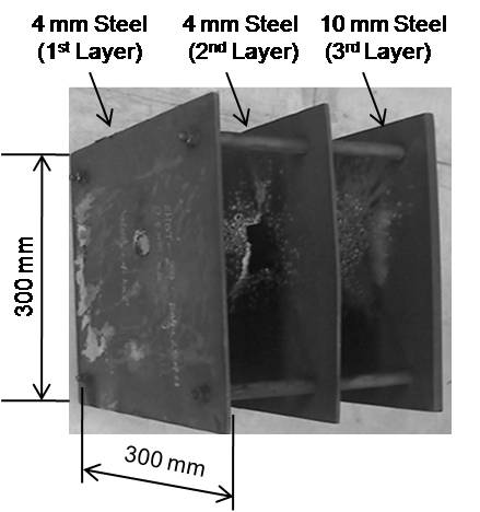
In these trials, it was observed that the penetration phenomenon is different at an impact velocity of 1.8 km/s than that at impact velocity of 3.1 km/s and 4 km/s. The fragment penetrated all three layers of the target at 1.8 km/s, whereas it could not penetrate the third layer at 3.1 km/s and 4 km/s. Further, it was observed that, with increase in impact velocity, the damage (hole size) on the target plates increases. At low velocity (1.8 km/s), the fragment partially eroded and did not form debris. However, at hypervelocity (>3.1 km/s), a debris cloud is formed behind the first layer. The debris cloud has sufficient coherency and energy to damage the second layer. The debris cloud behind the second layer could not penetrate the third layer and only a few dents were formed.
At hypervelocity, both target and fragment materials experience large deformations and shattering. Smooth Particle Hydrodynamics (SPH) is a mesh-free solver, which simulates flow and shattering of material. Hence, the SPH technique [10–11] of the Autodyn-3D software was used to simulate fragment penetration phenomenon at 3.1 km/s and 4 km/s. Material models for the fragment and the target are considered as a Johnson-Cook strength model with shock equation of state. A failure criterion for the fragment was chosen as Grady-spall (stochastic failure), which simulates the shattering of fragment at hypervelocity impact. The default critical strain value of 0.15 was considered, since WHA exhibits ductility. For SPH, the smoothening length shall be as low as possible to achieve near practical results. However, during the validation of the models, the authors found that smoothening lengths of 0.75 mm and 1 mm are adequate for the fragment and the target respectively. Simulation model details are as follows:
Fragment: Tungsten Alloy
- Equation of state: Shock
Reference density: 18.1 g/cc
Gruneisen coefficient: 1.54
Hugoniot parameters ‘c’: 4.029 m/ms and ‘s’: 1.237
- Strength model: Johnson-Cook
Shear modulus: 160 GPa
Yield stress: 1506 MPa
Hardening constant: 177 MPa
Hardening exponent: 0.12
Strain rate constant: 0.016
Thermal softening exponent: 1.0
- Failure model: Grady-spall with stochastic failure
Critical strain value: 0.15
Target: Steel 1006
- Equation of state: Shock
Reference density: 7.85 g/cc
Gruneisen coefficient: 2.17
Hugoniot parameters ‘c’: 4.569 m/ms and ‘s’: 1.49
- Strength model: Johnson-Cook
Shear modulus: 81.8 GPa
Yield stress: 250 MPa
Hardening constant: 350 MPa
Hardening exponent: 0.4
Strain rate constant: 0.04
Thermal softening exponent: 0.94
- Failure model: Johnson-Cook
Damage constants: D1: - 0.05; D2: 3.0; D3: - 1.0; D4: 0.015; D5: 0.06
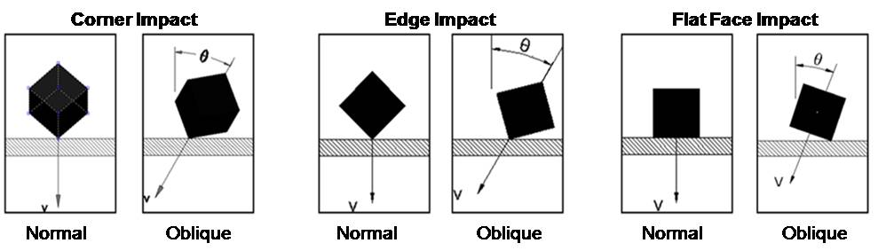
As the impact condition is a random phenomenon for a cubical fragment, simulations were carried out in all three orientations (corner, edge, and flat face) impacting the first layer of target as shown in Figure 2.
The comparison of simulation results with trial data is given in Table 1. The target plate damage profile achieved in the simulations and observed in the experiments is compared in Figure 3 and Figure 4 for impact velocities of 3.1 km/s and 4 km/s, respectively (where, Impact Vel is impact velocity; Sim is simulation result; Exp is experimental data; Co is corner impact; Ed is edge impact; and Fa is face impact.)
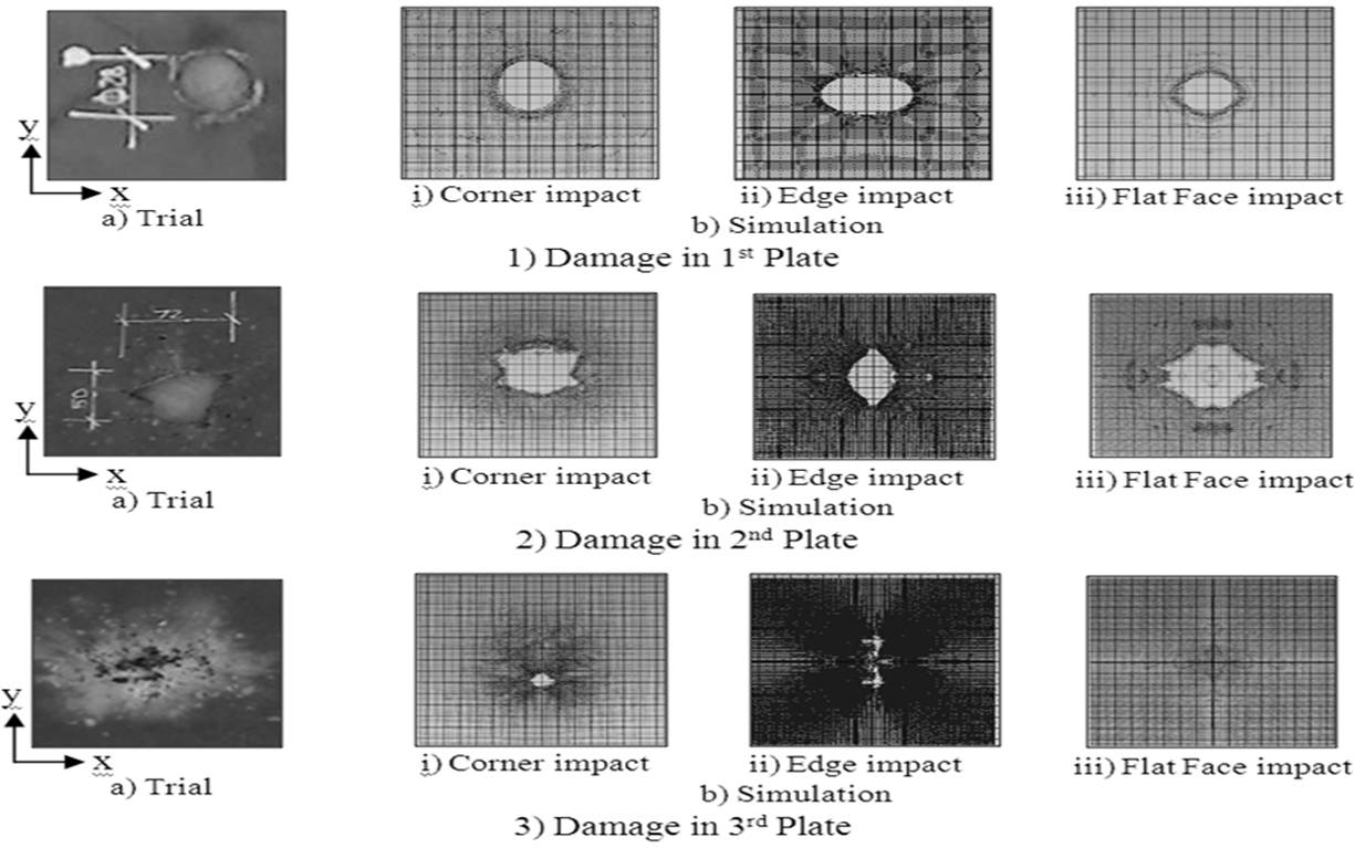
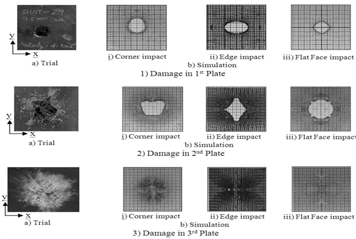
From Table 1, it is observed that, the hole size in the target plate depends on the impact condition. By observing the crater size and shape of hole at both velocities of 3.1 km/s and 4 km/s in the experiment, it appears that the fragment impacted somewhere between corner and face of a cubical fragment. The pattern of dents on the third layer of target plate in the simulations and in the two-stage gas gun trials is similar.
| ImpactVel (km/s) | Hole size in x and y directions (mm) | |||||||||
|---|---|---|---|---|---|---|---|---|---|---|
| Layer 1 | Layer 2 | Layer 3 | ||||||||
| Co | Ed | Fa | Co | Ed | Fa | Co | Ed | Fa | ||
| 3.1 | Sim | 22×30 | 38×24 | 22×22 | 58×48 | 30×54 | 70×60 | 16×12 | 10×40 | --- |
| Exp | 22x28 | 72×50 | No perforation | |||||||
| 4 | Sim | 25×32 | 40×25 | 23×23 | 60×50 | 60×80 | 62×62 | --- | 2×2 | --- |
| Exp | 23×28 | 73×86 | No perforation |
At hypervelocity, the debris cloud of the fragment and target materials impacts on the next layer of target. Exact details of the impact condition and the shattered pieces of target and fragment materials (that is, the debris density distribution) are not known. In addition, Autodyn-3D solver may cause some variation in the results due to energy errors and numerical approximations. However, as the simulation results were comparable with the experimental values, further simulations were carried out using the same models.
From the simulations it is observed that, after each target plate penetration, the density of the debris cloud decreases. Further, as the debris cloud is an expanding hollow ellipsoid in nature, the distance between the layers of target affects the damage. The fragment, orientation and obliquity at the time of impact also influence the concentration of the debris cloud.
Simulations for optimum fragment size
In the case of targets such as a ballistic missile, the typical impact velocity of a fragment with reference to the target is in the range of 3 km/s to 5 km/s. The fragment delivery system and the uncertainty in the target spatial orientation during engagement cause various impact conditions. Hence, arriving at an optimum fragment size, considering various impact conditions, is essential in design of a fragment delivery system.
The simulations were carried out with a WHA cubical fragment impacting on the three-layered steel target, having impact obliquity of 0° to 50°, in corner, edge and flat face orientations. The minimum fragment size required to penetrate all the three layers of the target was evaluated by considering the fragment size in steps of 0.5 mm at both impact velocities of 3 km/s and 5 km/s. However, in the cases where the fragment size was not affected, over a range of obliquity angles, the simulations were repeated with fragment size in steps of 0.1 mm. The effect of corner, edge and flat face of a 10.5 mm cubical WHA fragment impacting on the target at 3 km/s having normal impact is shown in Figure 5.
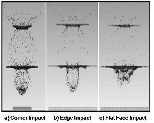
The fragment debris cloud at 70 µs shows that, penetration in the target depends on fragment orientation. In corner impact, a concentrated fragment debris cloud is available to penetrate third layer, whereas in edge and in flat face impact conditions, the debris cloud is comparatively less dense. Therefore, in the case of edge and flat face impact, the hole size is bigger in the second layer than that of corner impact (Figure 5).
From the simulations, the minimum fragment size required to defeat the target at both the velocities of 3 km/s and 5 km/s is arrived at and given in Table 2, for various impact obliquity and impact orientations.
| Impact Orientation | Obliquity | ||||
|---|---|---|---|---|---|
| 00 | 150 | 300 | 400 | 500 | |
| Corner | 10.5 | 10.3 | 10.5 | 10.5 | 13 |
| Edge | 11 | 10.1 | 11 | 13 | 17 |
| Flat Face | 15 | 11 | 11 | 11 | 15 |
| Impact Orientation | For: 00 ≤ θ < 300 | For: 300 ≤ θ ≤ 500 |
|---|---|---|
| Corner | 8.9×10-04θ2 –0.027θ+10.5 | 0.012θ2–0.83θ+24.5 |
| Edge | 0.004θ2 – 0.120θ+11.0 | 0.010θ2 – 0.50θ+17.0 |
| Face | 0.009θ2 – 0.403θ + 14.9 | 0.020θ2 – 1.4θ +35.0 |
| Cube Size (mm) | Successful Impact Obliquity Angles | Pkh | |||||
|---|---|---|---|---|---|---|---|
| Corner | Edge | Face | 00 | < 300 | < 400 | < 500 | |
| 10.5 | 00 – 400 | 50 – 250 | 190 – 260 | 0.31 | 0.68 | 0.59 | 0.47 |
| 11 | 00 – 430 | 00 – 300 | 140 – 400 | 0.77 | 0.90 | 0.75 | 0.67 |
| 11.5 | 00 – 450 | 00 – 340 | 110 – 420 | 0.77 | 0.92 | 0.87 | 0.74 |
| 12 | 00 – 470 | 00 – 360 | 90 – 440 | 0.77 | 0.93 | 0.90 | 0.79 |
| 13 | 00 – 500 | 00 – 400 | 50 – 460 | 0.77 | 0.96 | 0.97 | 0.87 |
Optimum Fragment Selection
The probability of target neutralization given a fragment hit (Pkh) needs to be assessed in conjunction with other system constraints. An optimum fragment delivery system requires a minimum fragment size which is capable of penetrating the target in all impact conditions, which may not be feasible in most cases. Hence, a methodology to evaluate Pkh, for selecting a fragment size has been developed to design a fragment delivery system.
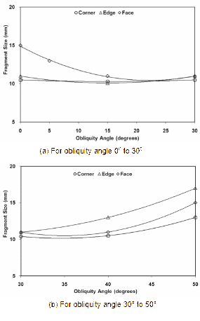
The data given in the Table 2, does not fit to a single trend line with desired accuracy. Hence, the data is plotted for 0° to 30° and 30° to 50° impact obliquities separately, as shown in Figure 6. The equation for the trend lines in the Figure 6, is given in Table 3, for both the ranges of obliquity. R2-value reflecting the goodness of fit for all the equations is close to 1. θ represents the impact obliquity angle in degrees with reference to normal to the target surface as shown in Figure 2. These equations, estimate the fragment size in millimetres for various impact conditions.
From Figure 6(a), it is observed that, in the flat face impact condition, for 0° impact, the minimum fragment size is 15 mm. As the obliquity increases, the size of the fragment reduces drastically until 15° and remains more or less constant until 30°. Since the reduction is significantly large until 15°, to check the trend an additional run at 5° obliquity was carried out, which resulted in a minimum fragment size of 13 mm. In the case of corner and edge impact conditions, the effect of obliquity is marginal up to 30°. From Figure 6(b), it can be observed that over the range of obliquity angles from 30° to 50°, the fragment size required to defeat the target increases gradually in all three cases of impact.
The probability of kill for each size of fragment, at various impact obliquities, is estimated using the equations given in Table 3. The cubical fragment has 12 edges, six faces and eight corners. The probability of kill for a given fragment hit ‘Pkh’ against the specified target is estimated by (1):
- where, E is the total number of successful edge impact conditions, C is the total number of successful corner impact conditions, F is the total number of successful face impact conditions, and T is the total number of impact conditions.
The number of successful conditions is estimated by varying the obliquity angle from 0° to 50° in steps of 1° and is given in Table 4.
It is observed that fragment impact orientation and obliquity angle affects the probability of kill given a hit. From Table 4, it is observed that, at 30° obliquity, kill probability is maximum in most cases.
Based on the overall system constraints, a suitable fragment size can be selected for a desired Pkh. For example, to yield a Pkh of at least 50% and 75% with obliquity angles < 50°, minimum fragment size required is 11 mm and 12 mm, respectively. Similarly, to yield Pkh of 75% with obliquity < 30°, minimum fragment size is 11 mm only. Thus, the methodology can be used, in selection of an optimum fragment size, to defeat a given target with desired probability of kill given a hit (Pkh), within a range of obliquities.
Conclusion
Two-stage gas gun trial data and Autodyn-3D simulations have been used to understand the fragment penetration phenomenon at hypervelocity. The simulation models were validated with the experimental data. Simulations were carried out for WHA cubical fragments impacting on the three-layered steel target, at various obliquities and orientations. Based on the results, in various impact conditions, the minimum fragment size to defeat the target was determined. For each of these fragment sizes, the probability of kill (Pkh) given a hit was computed, for a range of obliquities from 0° to 50°. Finally, a methodology is presented, to select an optimum fragment size to achieve a desired Pkh with impact obliquity. The methodology can be adopted in optimizing the design of fragment delivery system.
Acknowledgement
The authors are thankful to the Director, ARDE for his encouragement and motivation to carry out the study and for giving permission for publication.
References
[1] W.P. Schonberg and J.E. Williamsen, “RCS-based Ballistic Limit Curves for Non-spherical Projectiles Impacting Dual-wall Spacecraft Systems”, International Journal of Impact Engineering, 33, pp.763–770, 2006.
[2] J.E. Williamsen, W.P. Schonberg, H. Evans, and S. Evans, “A Comparison of NASA, DOD, and Hydro Code Ballistic Limit Predictions for Spherical and Non Spherical Shapes Versus Dual and Single-wall Targets, and their Effects on Orbital Debris Penetration Risk”, International Journal of Impact Engineering, 35, pp.1870–1877, 2008.
[3] W. Herrmann and J.S. Wilbeck, “Review of Hypervelocity Penetration Theories”, International Journal of Impact Engineering, 5, pp. 307-322, 1987.
[4] S. Ryan, M. Bjorkman, and E.L. Christiansen, “Whipple Shield Performance in the Shatter Regime”, International Journal of Impact Engineering, 38, pp. 504–510, 2011.
[5] J.D. Yatteau, R.F. Recht, and D.L. Dickinson, “High Speed Penetration of Spaced Plates by Compact Fragments”, Proceedings of 9th International Symposium on Ballistics, RMCS, Shrivenham, 1986.
[6] J. Huang, Z. Ma, L. Ren, Y. Li, Z. Zhou, and S. Liu, “A New Engineering Model of debris cloud produced by Hypervelocity Impact”, International Journal of Impact Engineering, 56, pp. 32–39, 2013.
[7] J.W. Walter and P.W. Kingman, “Numerical Modelling of High-obliquity Impact of a Compact Penetrator on a Thin Plate”, Proceedings of 16th International Symposium on Ballistics, San Francisco, C.A., 1996.
[8] D.L. Orphal, “Highly Oblique Impact and Penetration of Thin Targets by Steel Spheres”, International Journal of Impact Engineering, 23, pp. 687–698, 1999.
[9] M. Higashide, T. Koura, Y. Akahoshi and S. Harada, “Debris Cloud Distributions at Oblique Impacts”, International Journal of Impact Engineering, 35, pp. 1573–1577, 2008.
[10] C. Carrasco, O. Melchor-Lucero, R. Osegueda, L. Espino and A. Fernandez, “Damage-potential Comparison of Spherical and Cylindrical Projectiles Impacting on a System of Bumper Plates”, International Journal of Impact Engineering, 33, pp. 143–157, 2006.
[11] G. R. Johnson, “Numerical Algorithms and Material Models for High-velocity Impact Computations”, International Journal of Impact Engineering, 38, pp. 456–472, 2011.