
Volume 16, Number 3, November 2013
Temporal Aspects Of Enterprise Architecture
- 1 Atego, 5930 Cornerstone Court West, Suite 250, San Diego, CA 92121, US.
- 2 Syntell AB, PO Box 100 22, SE 100 55 Stockholm, Sweden.
Abstract
IEEE Std 610.12−1990 defines architecture as “the fundamental organization of a system embodied in its components, their relationships to each other, and to the environment, and the principles guiding its design and evolution.” [1] With previous versions of architecture frameworks, this was quite difficult. Modelling this evolution or the temporal aspects in architecture frameworks such NAF (NATO Architecture Framework), MODAF (Ministry of Defence Architecture Framework) or the Department of Defence Architecture Framework (DoDAF), have improved the state of the art. These architecture frameworks are based on the use of a four-dimensional ontology such as IDEAS where the spatio-temporal extent of an element is a crucial concept. This is embodied in DoDAF 2 as well as the re-engineering effort of MODAF (MODEM: which provides an IDEAS foundation basis for MODAF). Time can now be dealt with to a much greater extent than previously. The challenge is to identify areas of architecture where time can be modelled and how to take best advantage of it. The Unified Profile for DoDAF and MODAF (UPDM) delivers an implementation of DoDAF 2.0 and MODAF that provides a clear and concise way of expressing concepts dealing with time without requiring the user to become an expert in the DoDAF 2.0 or MODEM “internal wiring” and detailed ontological concepts. Since MODEM was not available when UPDM 2.0 was finalised, MODEM is a requirement for UPDM 3.0. MODEM has also been accepted as the basis for an upgrade of NAF and will make its appearance as NAF version 4.0. This paper will examine the temporal concepts defined in NAF (MODEM) and DoDAF 2.0 and show how time can be effectively integrated into a model to express essential temporal concepts.
Introduction
As Cummings noted humorously, “Time is what keeps everything from happening at once.” [3] William Shakespeare wrote in Julius Cesar, “Timing is everything.” [2] Philosophers have also mused on the concepts and flow of time for as long as human beings have roamed the planet. Time is no less important when building a military architecture framework. It is necessary to show how a configuration will evolve over time, how the variations will differ, common components, additional and emergent behaviour, how a system’s behaviour and capabilities change over time, and so on. Some examples of the use of time are:
- Modelling a sequence of events for different scenarios.
- Showing how a system changes over time and its different versions.
- Showing how the use of a system can change over time as defined by different scenarios.
- Capability modelling and how different systems support a capability over time.
- Showing how a system supports multiple capabilities at different phases of its lifecycle.
- Modelling system states to show time dependent behaviour as well as transitions and actions taken as a result of these transitions.
- Time dependent activity sequences.
- Scheduling deployment of systems over time.
- Personnel deployment and competency assessment.
- Data management lifecycles.
- Integrating system acquisition cost, deployment cost etc to show total cost of ownership.
- Showing cost versus time versus capability.
Architecture frameworks and ontologies
Arguably, the most widely used military enterprise architecture frameworks are the US Department of Defence (DoD) Architecture Framework (DoDAF), the British Ministry of Defence (MOD) Architecture Framework (MODAF) and the NATO Architecture Framework, (NAF). Military Architectural Frameworks such as DoDAF define a standard way to organize an enterprise architecture (EA) or systems architecture into complementary and consistent views. DoDAF was developed in the 1990s as the C4ISR architectural architecture framework. C4ISR v1.0 was released 7 June 1996, and was created in response to the passage of the Clinger-Cohen Act. It addressed the 1995 Deputy Secretary of Defence directive that a DoD-wide effort be undertaken to define and develop a better means and process for ensuring that C4ISR capabilities were interoperable and met the needs of the war fighter. C4ISR Architecture Framework v2.0 was released in December 1997.
DoDAF Versions. DoDAF v1.0 was released in August 2003. It broadened the applicability of architecture tenets and practices to all Mission Areas rather than just the C4ISR community. This document addressed usage, integrated architectures, DoD and Federal policies, value of architectures, architecture measures, DoD decision support processes, development techniques, and analytical techniques. The data format was expressed as CADM v1.01. [4] This was the start of the data-centric approach and placed emphasis on architecture data elements that comprise architecture products. However, it was widely misunderstood, misinterpreted and misused. Largely this was due to nature of CADM. As it was expressed as a set of disconnected entity relationship diagrams, there was no standardized means to create assertions regarding the architecture and demonstrate them. The ontological approach based on IDEAS concepts (discussed later) does in fact provide this capability. DoDAF Version 1.5 was released in April 2007 as a stop-gap update, mainly concerned with SOA (Service oriented architecture). [5–7] On May 28, 2009 DoDAF v2.0 was approved by the Department of Defence. [8]
DoDAF Views. DoDAF 1.0 and 1.5 contained four basic views: the overarching All Views (AV), Operational View (OV), Systems View (SV), and the Technical Standards View (TV/StdV). Each view is aimed at different stakeholders, and it is possible to create cross references between the views. Although they were originally created for military systems, they are commonly used by the private, public and voluntary sectors around the world, to model complex organizations such as humanitarian relief organizations and public services such as FEMA. The goal is to improve planning, organization, procurement and management of these complex organizations. All major DoD weapons and information technology system procurements are now required to document their enterprise architectures using DoDAF.
Evolution of MODAF/NAF. MODAF kept compatibility with the core DoDAF viewpoints in order to facilitate interpretation of architectural information with the US military. However, MODAF v1.0 added two new viewpoints. The new elements were the Strategic and Acquisition Viewpoints. These were later incorporated in DoDAF 2.0 were called the Capability (CV) and Project Views (PV). These were added to better contribute to MOD processes and lifecycles, specifically the analysis of the strategic issues and dependencies across the entire portfolio of available military capabilities within a given time frame. In MODAF v1.2, Service views were added to support the development of Service Orientated Architectures (SOA). These views, called SOV views in MODAF and SvcV views in DoDAF 2.0, were based on NAF 3. NAF 3.0 service views were however based completely on the MODAF 1.1 service views that were contained as part of the proposed package in MODAF.
DM2. DoDAF has a meta-model underpinning the framework, defining the types of modelling elements that can be used in each view and the relationships between them. DoDAF versions 1.0 thru 1.5 used the CADM meta-model, which was defined in IDEF1X (then later in UML) with an XML Schema derived from the resulting relational database. From version 2.0, DoDAF has adopted the IDEAS Group foundation ontology as the basis for its new meta-model. This new meta-model is called ‘DM2’; an acronym for ‘DoDAF Meta-Model’.
Ideas
IDEAS is the International Defence Enterprise Architecture Specification for exchange. DoDAF version 2.0 is based on the IDEAS ontology foundation. [9] The current versions of NAF and MODAF are influenced by IDEAS to some degree but are still UML profiles. An update to MODAF called the MODAF Ontological Data Exchange Mechanism (MODEM) is based entirely on the IDEAS Foundation ontology and is largely backward-compatible to MODAF 1.2.004. A large amount of documentation concerning MODEM has been produced. It has been published by the MOD as a replacement for MODAF and will be used as the basis for NAF version 4. The purpose of IDEAS is to develop a data exchange format for military Enterprise Architectures. This goal is to provide seamless sharing of architectures between the partner nations regardless of which modelling tool or repository they use. The initial scope for exchange is the architectural data required to support coalition operations planning:
- Systems—communications systems, networks, software applications, etc.
- Communications links between systems.
- Information specifications—the types of information (and their security classifications) that the communications architecture will handle.
- Platforms and facilities.
- System and operational functions (activities).
- People and organizations.
- Architecture meta-data—who owns it, who was the architect, name, version, description, etc.
Before going further, it would be best to explain a few of the main concepts in the IDEAS foundation key objects .At the base of the IDEAS ontology is the ‘Thing’. There are three types of Things:
- Types (which are like sets);
- Tuples (ordered relationships); and
- Individuals (not persons, but Things that have spatial and temporal extent—spatio-temporal extent.)
Mereology is a collection of axiomatic first-order theories dealing with parts and their respective wholes. In contrast to set theory, which takes the set–member relationship as fundamental, the core notion of mereology is the part–whole relationship. Mereology is both an application of predicate logic and a branch of formal ontology. For further information see IDEAS [9]. The IDEAS foundation key objects are shown in Figure 1.
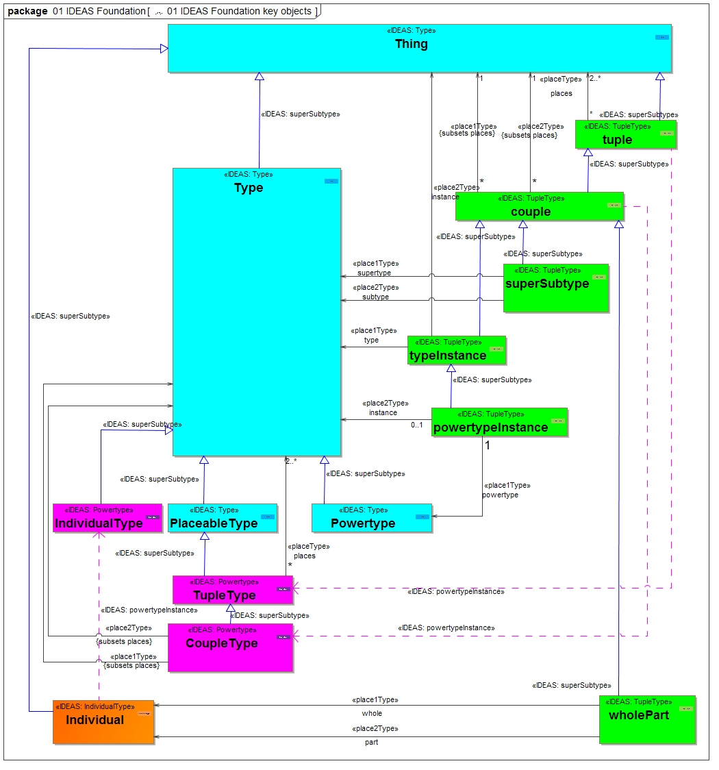
Foundation Objects. None of these foundation properties found in Figure 1 are unusual; they are all used in everyday reasoning:
- Individuals, things that exist in 3D space and time—that is, have spatial-temporal extent.
- Types, sets of things.
- Tuples, ordered relations between things—such as, ordered pairs in 2D analytic geometry, rows in relational database tables, and subject-verb-object triples in Resource Description Framework.
- Whole-part—such as components of a service or system, parts of the data, materiel parts, subdivisions of an activity, and elements of a measure.
- Temporal whole-part—such as the states or phases of a performer, the increments of a capability or projects, the sequence of a process (activity).
- Super-subtype—such as a type of system or service, capability, materiel, organization, or condition.
Higher-level Objects. These can then be used together to model kinds of things and their relationships. In enterprise architecture kinds of things are usually more interesting than individuals and these elements are therefore of great importance:
- BeforeAfter (IDEAS foundation element).
- BeforeAfterType (IDEAS foundation element).
- TemporalWholePart (IDEAS foundation element).
- TemporalWholePartType (IDEAS foundation element).
- Desired Effect (DM2 element).
- Work Streams (MODEM and DM2).
- Sequence of events in the form of sequence diagrams (MODEM).
- State modelling (MODEM).
- Milestones (MODEM).
There are a number of items above that are pure IDEAS elements. The fact that they are allowed for direct use in DM2 actually represents a problem since this places considerable responsibility on the modeller. Although Milestones are part of MODEM/ MODAF, they are not part of the DM2 vocabulary. The closest that DM2 gets to this is by assuming that a kind of project contains a kind of activity that is assumed to be a milestone by the modeller.
Ideas examples
Since the main topic of this paper deals with timing concepts, a few examples that describe their use based on IDEAS foundation elements may be appropriate.
Figure 2 describes a simple wholePart relationship between a distinct laptop computer and its display. It should come as no surprise that the set of all wholePart relationships should have an instance within it that is the relationship between the laptop and the display. Both of these individuals have a defined spatio-temporal extent. The wholePart relationship can contain both spatial as well as temporal wholeParts and the next example shown in Figure 3 deals with a wholePart that is completely temporal. IDEAS created a special subset of wholePart where completely temporal wholeParts can be dealt with.
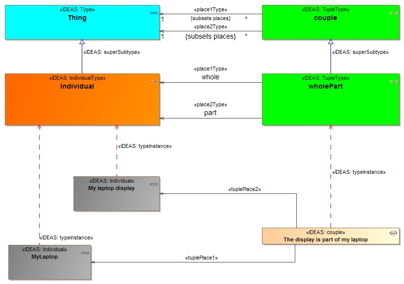
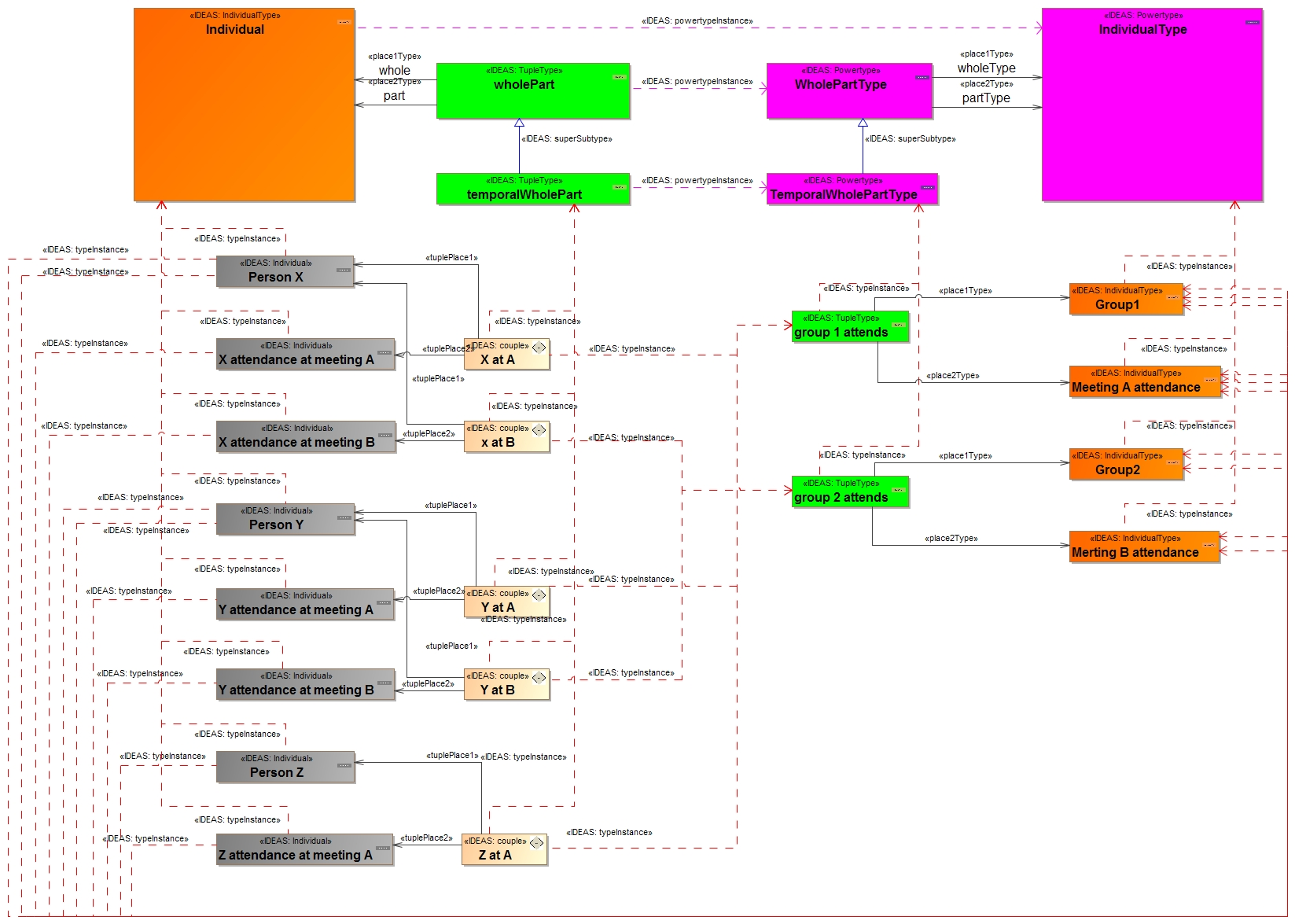
Figure 3 shows an example that exemplifies temporalPart as well as TemporalWholePartType.
The example shows a group of people X, Y and Z. They have attended meeting A and B (Z only attended A) and their attendance is therefore a temporal part of their whole life. This makes it possible to create a set of instances of the temporalWholePart set that connects as an example Person X with X attendance at A. This is shown by the couple X at A and similar connections are described for the other persons.
This starts to bring us into the area of time handling made possible by MODEM as well as DoDAF 2.
A simple project schedule diagram has been created to help explain the temporal aspects further and also includes discussions of higher level temporal elements and their use. Figure 4, apart from being unreadable looks extremely complicated. However, it is actually almost completely an explicit DoDAF 2 PV-2 model. It contains all of the DoDAF defined necessary elements for a PV-2 model. DoDAF 2 actually allows exactly 150 different optional element types as well for this view something that poses quite a challenge for any tool palette. It also contains some elements defined as optional for the view and some that a modeller is actually not allowed to use: notably Individual and IndividualType. These are used here since to exclude them would make it difficult to see where different elements point to.
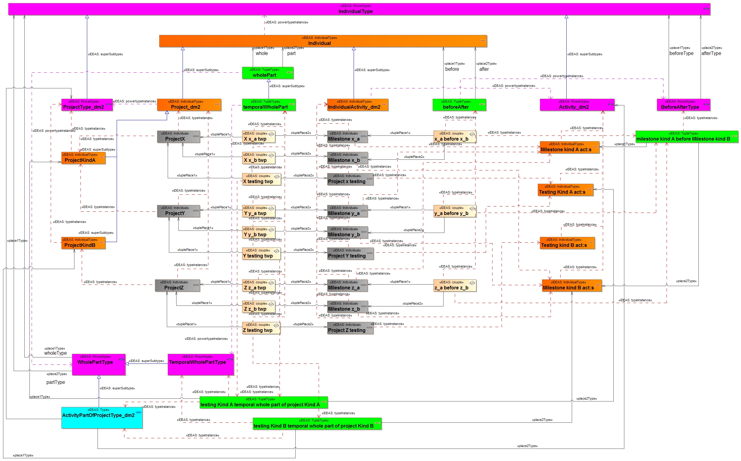
Figures 5 to 9 detail Figure 4 in a more legible format. Figure 10 contains the MODEM equivalent of Figure 4 and some discussions concerning the reason for the differences.
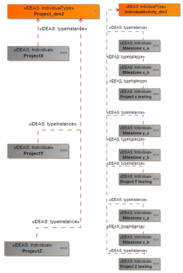
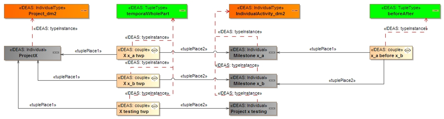
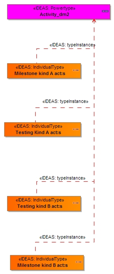
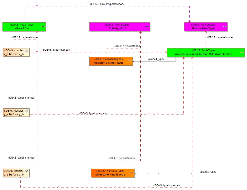
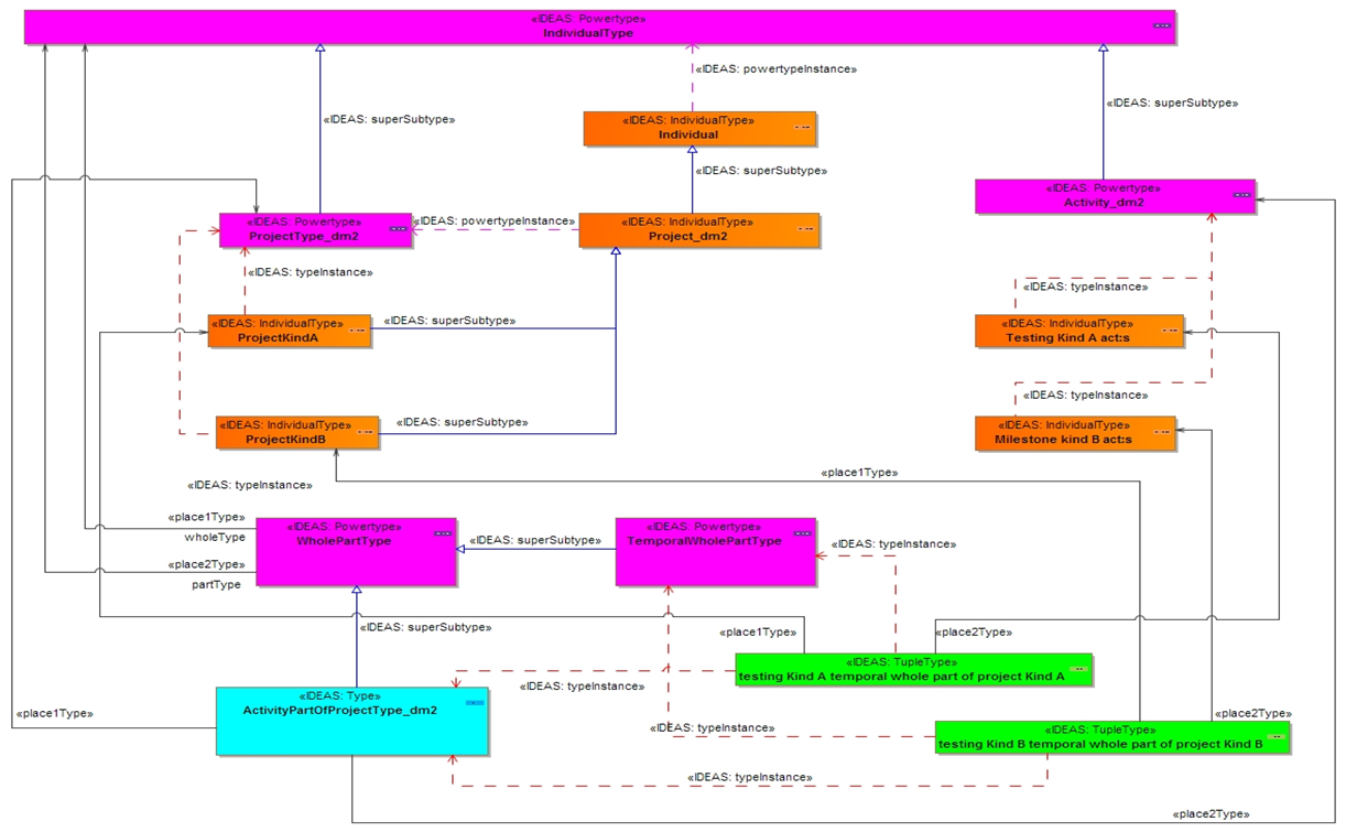
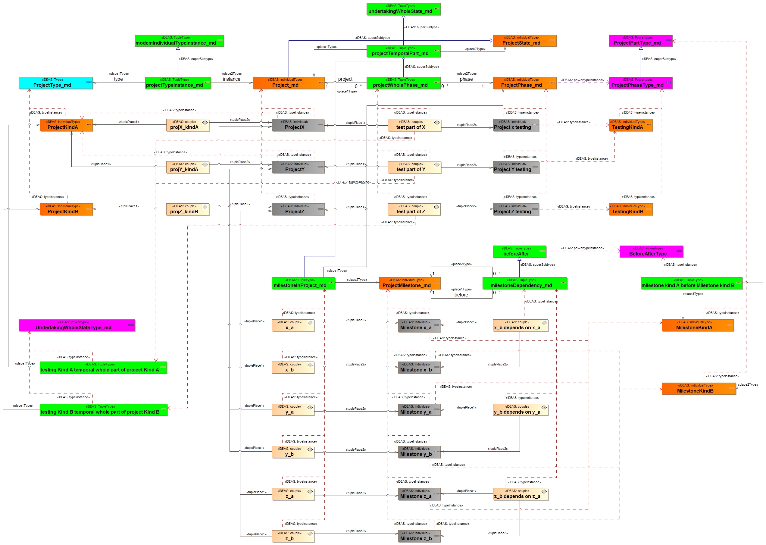
Figure 5 shows:
- A set of individual projects are contained in the example model and a set of example activities.
- Since milestones are not a part of the DoDAF vocabulary activities have been chosen instead and there are a few different individual milestones as well as a completely different type of activity (testing) associated with each individual project.
Figure 6 associates projects with individual activities:
- The above shows project X with three different individual activities. Two of these are milestones and one is a testing activity.
- All three activities are temporal parts of the X project and before after is used to indicate that milestone a is before milestone b. Note that there is no indication of the time interval in between.
Activity in DoDAF 2 is the set of all subsets of the set of all individual activities (it is a powertype) and therefore the four sets defined here are instances of the Activity_dm2 set.
- Testing Kind A activities contain: Project x testing and Project y testing.
- Testing Kind B activities contain: Project z testing
- Milestone Kind A activities contain: Milestone x_a, Milestone y_a and Milestone z_a
- Milestone Kind B activities contain: Milestone x_b, Milestone y_b and Milestone z_b
Figure 8 shows an example of a BeforeAfterType instance
- Since all instances within Milestone Kind A activities occur (that is, end) before all instances within Milestone Kind B activities an instance of BeforeAfterType can be created in the form of the element milestone Kind A before Milestone Kind B.
- This element contains all of the before after relationships defined in the example.
Figure 9 carries this further by showing a TemporalWholePartType example:
- As was shown previously, the testing activities can be combined into two distinct subsets that are instances of Activity (since it contains all possible subsets).
- This also means that instances of TemporalWholePartType can be created that contain the relationships that deal with temporal whole parts for testing Kind A and testing kind B.
- These in turn are instances of the DM2 element activityPartOfProjectType.
Figure 10 shows the same project model as in figure 4 as a MODEM model. As can be seen this differs somewhat from the representation using DM2, a detailed study will however reveal that the main difference is that DM2 makes use of IDEAS foundation elements directly to quite a large extent whereas MODEM does this much more sparingly if at all. There is considerable advantage in this since it implies that modelling is more constrained and regulated. In DM2 an attempt to constrain modelling is presented as a set of textual rules available in the DoDAF documentation. Allowing direct use of elements such as wholePart in DM2 makes it possible to consider a Country to be part of a Point. This kind of usage is constrained in DM2 by textual rules rather than by the model itself which is the case in MODEM.
The unified profile for dodaf and modaf (updm)
The Unified Profile for DoDAF and MODAF, (UPDM) initiative was started by members of INCOSE, the OMG, the US Department of Defence, and the British Ministry of Defence. UPDM provides a consistent, standardized means to describe DoDAF and MODAF architectures in SysML/UML-based tools as well as a standard for interchange. The concepts found in the Systems Modeling Language (SysML) such as parametrics, blocks, complex ports, enhanced activity modelling, and cross-cutting constructs improve the state of the art for systems engineers and architects. The formal meta-model basis of UPDM also provides a basis for trade-off analysis, model execution, requirements traceability, and the transition to systems development and implementation. It is important to stress that UPDM is not a new architecture framework. Instead, it provides a consistent, standardized means to describe DoDAF, MODAF and NAF architectures in UML-based tools as well as a standard for interchange [8,10–14].
The Ministry of Defence Architecture Framework (MODAF) [15] was published as early as 2003 and is supported in its latest version by UPDM. The work that resulted in the MODAF Exchange Model (MODEM) [16] builds on MODAF and is an ontological model based on IDEAS [9]. It is very close to MODAF at leaf level. MODEM is currently being proposed as a candidate for the next version of the NATO Architecture Framework.
Updm examples
The following section contains several examples of the use of UPDM to express temporal aspects of architectures. The set of concepts listed in the introduction cannot all be described due to the limitations of space for this paper. It is also worth noting that that list is a short subset of all the concepts that are possible to express in UPDM. Consequently we will touch on a demonstrative subset.
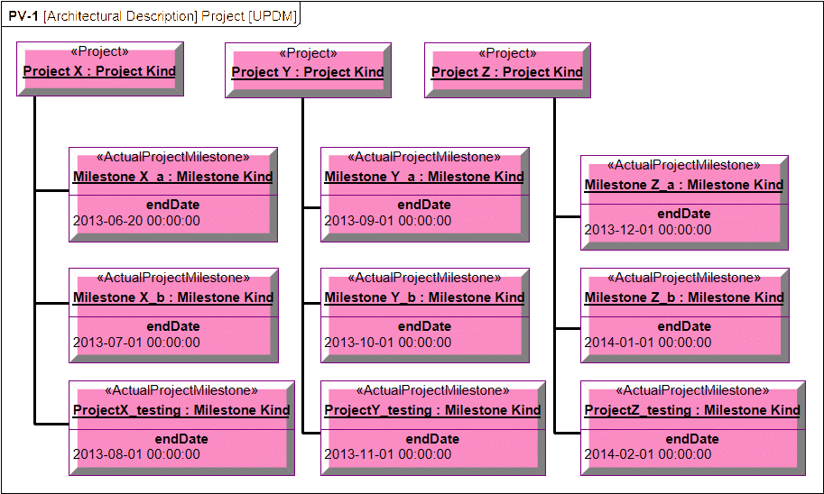
Project Sequences. The PV-2 model shown in Figures 4 and 10 has been redrawn using UPDM in Figure 11. The same information is shown but in a different manner. UPDM project and milestone types are defined as classes with the project class comprising a composite aggregation of its milestone types. Actual projects and milestones can then be created from these classes in the form of project and milestone instances. These instances contain specific data values for the defined attributes. For example, Figure 11 shows three projects each with a set of milestones as well as additional information regarding organization, fielded systems, milestone and project sequences, starting and ending dates, etc. Because of the infrastructure supporting UPDM, most of the detailed relationships shown on the previous diagrams is implicit.
Systems Changing Over Time. It is obvious that systems change over time for a variety of reasons. These include:
- system lifecycle of design, manufacture, deployment, maintenance, retirement;
- changes for mission-based configurations; and
- changes due to maintenance.
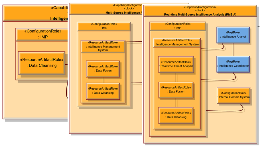
Take the example of an aircraft. Given the above listed changes; is it the same aircraft because it has the same tail number, or is it a different aircraft and should we consider it so when creating an architecture mode that includes this aircraft? DoDAF SV-1 diagrams are used to show system configurations as well as interfaces between systems and interactions. Figure 12 contains several SV-1 diagrams showing the evolution of an Intelligence Analysis (IA) system over time. The acronym IMP refers to information (in any medium or form), material, or persons that can be collected and analysed to produce intelligence. Starting from left to right, the initial IA system contains the IMP with Data Cleansing as well as a human Intelligence Analyst and Internal Communications System and the interfaces between them. The central system groups the additional Data Fusion into an Intelligence Management system along with Data Cleansing. The final version adds Real-time Threat Analysis and an Intelligence Coordinator. All variations of this system provide the same basic capability. What varies is the degree to which they do so. By building the different configurations, this provides a construct against which trade-off analysis can be performed. This is especially important when considering a cost-benefit analysis. As UPDM leverages SysML, constructs such as parametric equations and simulation can be utilised for this purpose.
Scheduling System Deployment. As mentioned earlier, the project view shown in Figure 6 also is used to show when systems are deployed over time. When linked to the capabilities, these can be used to show capability coverage as well as gaps using the CV-3 report. O’Shea et al [17] expanded this view creating a Fit for Purpose view adding cost vs. budget, project dependencies, broken constraints, etc. as shown in Figure 13. Although UPDM simplifies the information involved in defining project views, the sheer quantity of detail involved in managing over multiple projects would be overwhelming for decision makers. Consequently, it becomes necessary to express the information in a form that is more fit-for-purpose.
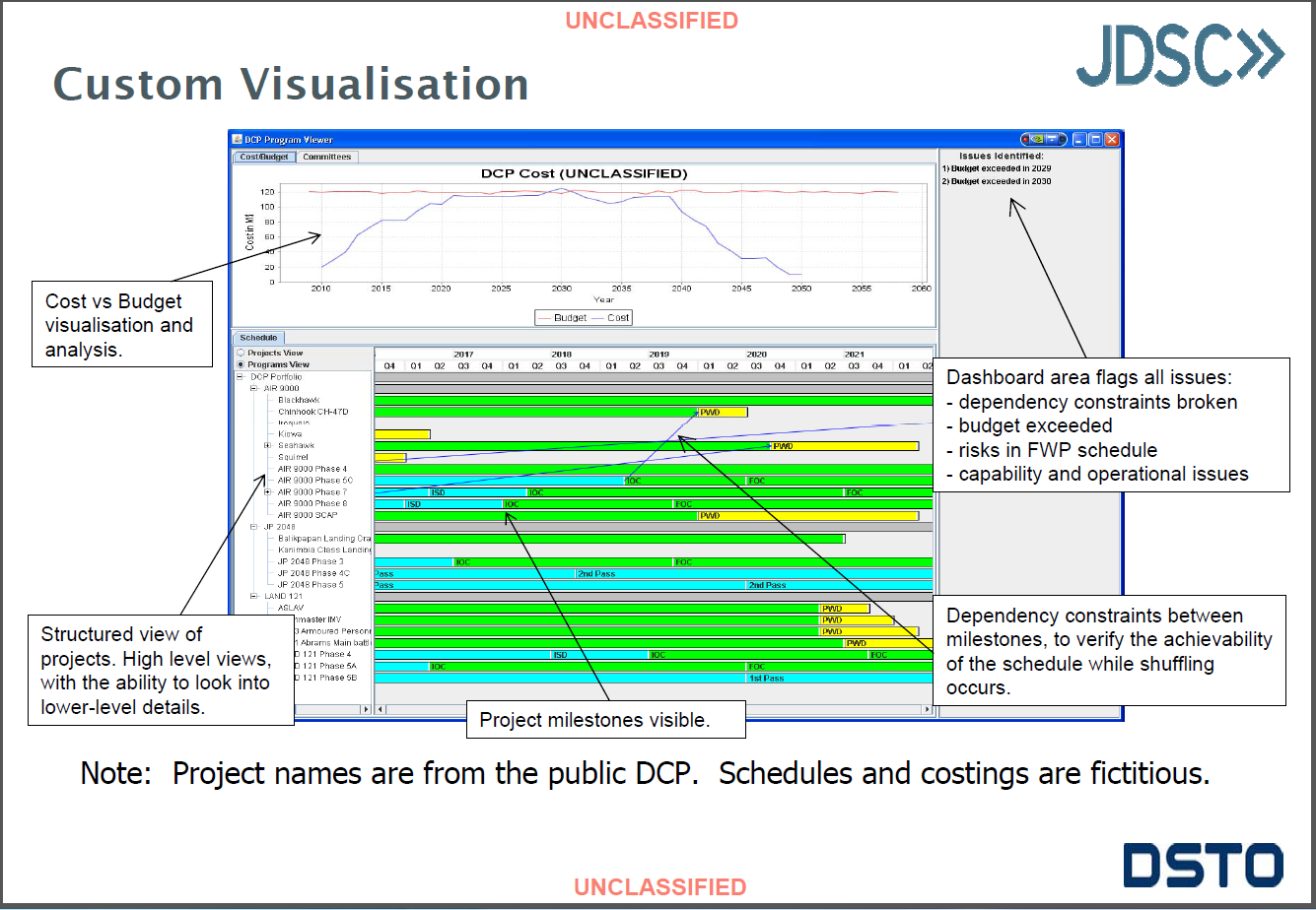
The work described in O’Shea [17] applies a UPDM-based architecture development approach to capture capability development information with an emphasis on developing a fit-for-purpose visualization to support decision making. This work includes the development of prototype visualization software to facilitate decision support from architectural models. Users have the ability to shift projects on the timeline to determine the impact on overall budget as well as to ensure that costs for fiscal periods are not exceeded. Shifting the timeline will also affect equipment availability, thus impacting the ability to deliver essential capabilities. Without the use of this tool, the work would largely be done by hand or by using multiple disconnected data sources. Finally, the use of the UPDM repository will allow architects to further develop integrated architectures within the same repository rather than creating multiple disconnected models. Sections of the model can be extracted to form the basis of the development of architectures that support the required capabilities. This provides continuity throughout the development lifecycle. This “Fit for Purpose” visualisation is exactly what is needed by decision makers as well as what was envisioned by the stakeholders of UPDM. Effective graphics have been created directly linked to the data repository. Changing the graphic changes the data and changing the data changes the graphic.
Event and Interaction Sequences. The DoDAF OV-6c diagram can be used to describe operational activity sequence and timing that traces the actions in a scenario or critical sequence of events. The SV-10c provides a time-ordered examination of the system data elements exchanged between participating systems (external and internal), system functions, or human roles as a result of a particular scenario. Each event-trace diagram should have an accompanying description that defines the particular scenario or situation. Each SV-10c in the Systems and Services View may reflect system-specific aspects or refinements of critical sequences of events described in the Operational View. An example SV-10c is shown in Figure 14.
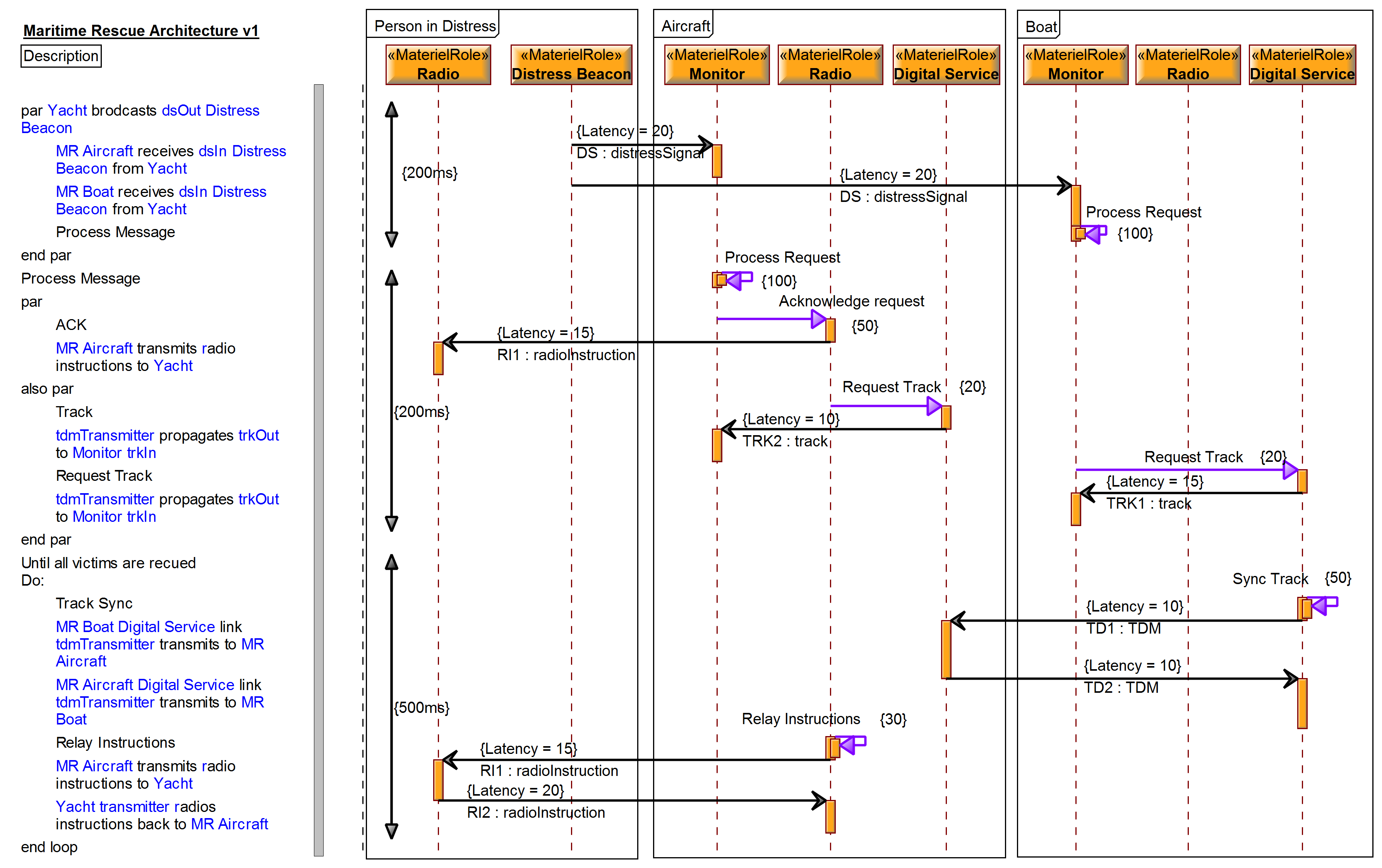
The diagram is owned by the system context. The elements shown are parts of this system. The interactions (horizontal flows) are those already defined in the in the SV-1 and SV-2. Time progresses from the top to the bottom of the diagram. Additional timing information has been added such as transmission latency and processing duration. Timing constraints are shown as vertical arrows on the left of the diagram. Static analysis can be done by collating the timing information on these diagrams into spread sheets for numerical analysis. This provides architects with the ability to evaluate the performance of potential variant architectures. As the interactions are limited to those available in the configuration, consistency is enforced by the model. Simulation of behavioural portions of the model can be used to verify timing and behaviour of the model for trade-off analysis and requirements specification. Having run the simulation, the timing information can be displayed on the sequence diagram, allowing the architect to evaluate alternate solutions.
State-Based Specification. The SV-10b state diagram is a graphical method of describing how a system (or system function) responds to various events by changing its state. The diagram basically represents the sets of events to which the systems in the architecture will respond (possibly by taking an action to move to a new state) as a function of its current state. Systems can also respond to events and remain in the same state. In this way, a cross reference can be created to document the available functionality of a system within each state. Each transition specifies an event and an action. Guard conditions including timing information can be added to these transitions to specify time-based transitions. The before-after concept described earlier is the underlying mechanism for the transitions. This is called a directed relationship in that it shows the transition from one state to another as shown in Figure 15Another aspect of UPDM is the ability to show the interaction of more than just data. Energy, people, systems, organizations, and software can be shown to be exchanged (or travel) between systems. This provides the ability to create architectures for logistics among other applications. The example shown in Figure 10 shows a simplified case management lifecycle for the delivery of a parcel. It shows the various states of the parcel, activities that can be performed on the parcel while in that state, valid transitions to other states, error conditions, and how the processing of the parcel changes in relation to its state. The SV-10b is normally used to show the state-based behaviour of a system.
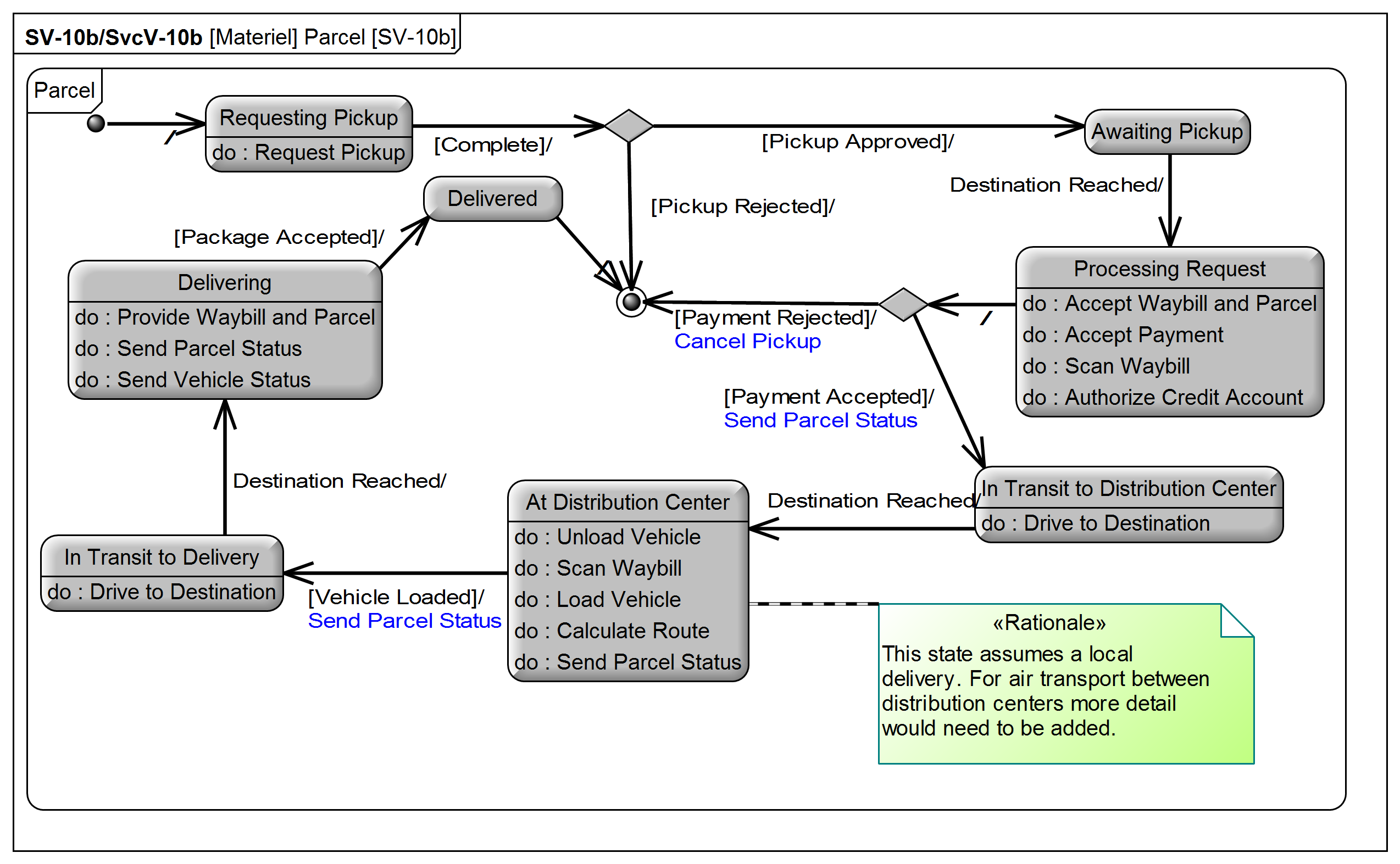
The state machines shown above can be executed in UPDM tools. Timing constraints can be added to the transitions as well as embedded in the operations and activities of the state machine to demonstrate the behaviour of the owning entity including time based behaviour. By executing this state machine in conjunction with others in the model, the architect can perform behavioural and timing analysis of the architecture. This provides a means of performance based trade-off analysis.
Conclusion
Military architecture frameworks are powerful tools for enabling architects to define, design, plan, and implement enterprise architectures. The latest versions of frameworks such as MODEM and DoDAF 2.0 are based on the ontological concepts in the IDEAS foundation objects. These concepts provide the detail necessary to express temporal concepts in precise and testable ways. Using tools implementing the UPDM standard, architects now have the tools to build the complex models needed to manage both government and industrial enterprises. UPDM tools provide the means to develop these architectures in a far more useable format. This paper has described examples of these concepts using UPDM Atego’s Artisan Studio. There are numerous other examples and it is hoped that these can be explored in future papers.
References
[1] IEEE Std 610.12−1990, IEEE Standard Glossary of Software Engineering Terminology.
[2] W. Shakespeare, 1613, The Complete Works of William Shakespeare, H. Pordes, 529 Finchley Road, London, NW3 7BH, England.
[3] R.K. Cummings, The Girl in the Golden Atom, University of Nebraska Press, p. 46, 1992 Retrieved 9 April 2011.
[4] DoD, 2003, Architecture Framework Version 1.0 Volume I: Definitions and Guidelines, 30 August 2003.
[5] DoD, 2007a, Architecture Framework Version 1.5, Volume I: Definitions and Guidelines, 23 April 2007, DoD Architecture Framework Working Group.
[6] DoD 2007b, Architecture Framework Version 1.5, Volume II: Product Descriptions, 23 April 2007, DoD Architecture Framework Working Group.
[7] DoD 2007c, Architecture Framework Version 1.5, Volume III: Product Descriptions, 23 April 2007, DoD Architecture Framework Working Group.
[8] DoDAF/DM2 2.01, Version 2.01 as of 1 April 2010. Version Description Document for the DoD Architecture Framework (DoDAF) and DoDAF Meta Model (DM2), Version 2.01 can be downloaded from http://cio-nii.defense.gov/sites/ dodaf20/products/DoDAF_DM2_VDD_v2-01.doc.
[9] IDEAS, 2012, Online http://www.ideasgroup.org.
[10] M.C. Hause, “The UPDM RFC Development Project—An Exercise in Model-Based Virtual Team Development or ‘Practicing What We Preach’”, 5th Annual Israeli National Conference on Systems Engineering, Herzlia, Israel, 2009.
[11] Object Management Group (OMG), 2005, Military Architecture Framework Request for Information, Available from www.omg.org. [Accessed April, 2005].
[12] Object Management Group (OMG), 2010. Unified Modeling Language: Superstructure version 2.3 /2010-05-05. [online] Available from: http://www.omg.org/spec/UML/2.3/Superstructure/PDF/ [Accessed November 2012].
[13] Object Management Group (OMG), 2009, Service oriented architecture Modeling Language (SoaML), available at http://www.omg.org/spec/SoaML/
[14] Object Management Group (OMG), 2012, Unified Profile for DoDAF/MODAF (UPDM) 2.0, available at http://www.omg.org/spec/UPDM/2.0/PDF, Accessed Nov 2012.
[15] MOD Architectural Framework, Version 1.2, 23 June 2008, https://www.gov.uk/mod-architecture-framework.
[16] MODEM: MODAF Ontological Data Exchange Mechanism, October 2012, https://www.gov.uk/mod-architecture-framework.
[17] K. O’Shea, Kevin, P. Pong and G. Bulluss, Fit-for-Purpose Visualisation of Architecture to Support Defence Capability Decision-Making, Joint Operations Division, Defence Science and Technology Organisation, DSTO-TN-1098, 2012.