
Volume 16, Number 3, November 2013
Electro-Textile Development For Embedded Networks In Combat Uniforms
- 1 Defence R&D Canada Valcartier. 2459 De la Bravoure Blvd, Québec (QC), Canada G3J 1X5.
- 2 Bennett-Fleet Québec Inc. 380 Fortin Street, Québec (QC), Canada G1M 1B1
Abstract
Recent developments in materials have enabled the integration of more specific functionalities into textile fabrics, such as the exchange of information or energy distribution. With the increased use of peripheral electronic devices such as communications and sensors, a soldier requires the distribution of information and power around the body. The use of efficient interconnection technologies, embedded directly in electro-textiles inside a soldier’s uniform, would optimize the use and distribution of available power and information. This could lead to important weight savings but also in increased system availability and reliability. This paper presents the development of new wired interconnection and network topologies that could be applied to a combat uniform design. A description of different conductive textiles is presented as well as textile connectors and network topology that were selected for a prototype demonstrator.
Introduction
Recent developments in materials and nanotechnologies have enabled the integration of more specific functionalities into textile fabrics. For example, textiles that changes colours depending on the temperature of the body, or thin membranes that enhance heat exchange and/or breathability in certain conditions, have been used by athletes in international competitions. More interesting is the miniaturization and compact packaging of electronics and sensors, which enable monitoring of the body and/or its surrounding environment, which could then be integrated into the textile. In the past few years, there has been active research and development of ‘intelligent textile’ materials that include active functionality directly built into the textile of the clothing. The term ‘electro-textile’ has also been widely used to describe the interconnections for energy and/or information exchange between different areas of the clothing. The integration of intelligent textiles, electronics and sensors into modern clothing, such as a combat uniform, will be driven by an increased interoperability between all the embedded functions through an efficient and normalized physical interface such as an electro-textile. In that regard, electro-textiles will be a critical building block for the future design of combat uniforms. Solid and direct connections between electronics are useful for military purposes in order to minimize the risk of hacking data, unlike wireless solutions which can be intercepted. Additionally, wireless solutions have limited ability to transport energy to peripheral devices.
In the current Canadian approach to the design of soldier systems [1], the most important aspects to consider are integration, easy reconfiguration, and usability (that is, user acceptance). The simplest and most feasible way to distribute complicated electronics or computers around a soldier’s body is to employ electronic components that could be attached to transmission lines in textiles. The electronic component could then be replaced, exchanged or upgraded depending on the mission requirement. Thus, in the proposed approach, the electro-textile is embedded in the various fabrics of a combat uniform that carries only transmission lines and connectors, which allows the clothing to be flexible and comfortable (and therefore ‘transparent’ to the user. Also, it will avoid some of the long-term reliability issues [2] related to embedded electronics inside clothing that have to survive the rigours of the harsh military environment as well as repeated washing and drying cycles.
This paper describes electro-textiles technologies that were developed for the distribution of power and for information exchange inside a combat uniform. The structure of the paper is as follows. Section 2 describes the physical constraints of textiles in a military environment. Section describes the different electro-textile conductor technologies that were developed in the project. Reliability and performance issues are also discussed. This is followed in Section 4 by a description of the proposed textile connector configuration. Section 5 describes the prototype electro-textile clothing system currently under development. Finally, conclusions and future work are presented in Section 6.
Physical constraints of electro-textile in military environment
In order to realize practical electro-textile clothing systems, certain mechanical and electrical properties must be validated to ensure long term stability and reliability. After an extensive literature survey, it was noted that there has been very little research and development that systematically evaluates the physical behavior of electro-textiles in simulated military conditions. Moreover, in the literature, each research project uses its own evaluation method, different from normalized textile testing method such as ASTM or ISO. This makes the interpretation of results difficult to understand in term of mechanical and electrical behavior of electro-textiles.
Any electro-textile incorporated into a uniform will experience abrasion either from the outside or even the inside with the human skin. Any textile-embedded conductor should be protected and/or disposed away from areas of high bending angle where wear usually occurs, such as at the knees or elbows. Intermittent failure in signal transmission with the lack of conductive contacts is usually the result of abrasion on conductors. In some rare circumstance, short circuits between different conductors might occur. The need to protect any electro-textile from abrasion is a significant difference between conductors used in uniforms and those used in more conventional electronic devices. As discussed in [3], a typical uniform fabric will experience a large number of flex cycles during its useful life. Given the potential for relatively quick fatigue failure, the fatigue life of any metallized textile conductor should be considered in the overall clothing design. Also, multiple paths signal redundancy should be included into the basic design of the electro-textile to increase long-term reliability.
One of the most difficult tests for electro-textiles is to go through normal clothing wash cycles. Since electro-textiles are usually made of metallic yarns, interconnections and even connectors, they have to endure the harsh environment of detergents and water inside a high-temperature washing machine. Electro-textiles have to survive simultaneously these conditions and be operational after being properly dried. This also raises the problem during the operational use of electro-textile under rainy conditions, submergence in water (such as when crossing a river) or even with the sweat of soldier. As described in [4], most research pertaining to washability involved testing in controlled conditions metal-plated fabrics not electro-textiles. Not surprisingly, conductive fabrics lost their conductivity after repeated laundering.
Other technologies are slowly emerging from industry and R&D agencies to solve the wash cycle issue but also the operability of electro-textiles in wet conditions. One promising approach consists in packaging conductive fibres into a semi-permeable membrane structure that allows a certain amount of water to enter inside, but also to escape more easily. Drying of the electro-textiles is consequently much quicker, thus preventing long-term oxidization of the metallic yarns. From an operational point of view, the electro-textile might stop functioning properly when soaked in water but it will more likely return to operational status quickly when dried out. By monitoring the ‘wetness’ of electro-textiles, it should be possible to allow harmonious degradation of the electro-textile and then allow recovery of the system when drier operational conditions return.
In the military environment, electromagnetic interference (EMI) could be caused by electro-textiles inside clothing via the signal or the power lines especially when a good ground connection is not available. EMI will be produced when the electrical impedance between components, circuits, or equipment having some mutual impedance through which currents or voltages in one circuit can cause currents or voltages in another—the mutual impedances vary greatly depending on the frequency and power density. Simple steps could be taken to reduce EMI from an early design perspective inside an electro-textile system. As a first step, all unused transmission line or conductive layers should be linked to the ‘electronic ground’ of the clothing system. In this case, a link to the real ground might be necessary depending on the requirement of the system. For humans, the use of conductive boots might then be necessary to reduce EMI. Electronic filters (capacitive and/or inductive) are another means of reducing emissions causing EMI by absorbing the current and voltage surges or spikes produced on a transmission line. Electromagnetic shields can also be added to attenuate EMI between sources and susceptible equipment.
Electro-textile development
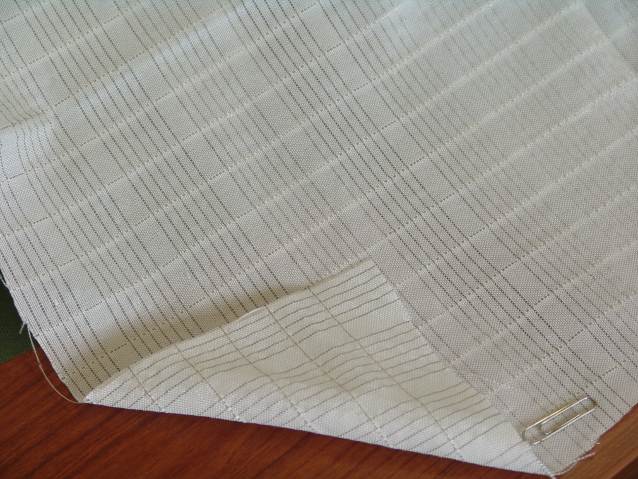
One of the simplest ways to integrate conductive yarn into the fabric in an electro-textile is to weave it as one of the warp or weft yarns. Because of its Cartesian X-Y design, plain weave has been mainly used since its construction represents the most elementary and simplest textile structure, in which no lateral yarn movement is possible and a very stable fabric structure is created. Also, by embedding multiple conductive yarns, redundant transmission line paths could be created. One major drawback of this technique is the interconnections between the X and Y (warp and weft) yarns for signal transmission. Figure 1 shows an image of a typical conductive line weave structure produced by Lincoln Fabrics [5]. Depending on the application and on the type of conductive yarns, reliable transmission line network could be difficult to construct and manage. This is especially the case when clothing is made of multiple individual pieces where electric signals have to be passed through the sewing seams.
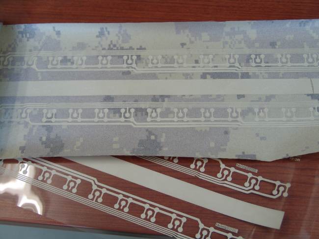
Another type of technology is available for the creation of a conductive layer on textile. The deposition of a metallic thin film could be made inside a low-temperature vacuum chamber where plasma induction deposits a very thin layer of metal over the inner surface of the textile. By using a subsequent chemical etching process, a portion of the deposited metal can be removed to form transmission lines. A prototype electro-textile, produced by Stedfast [6], is shown in Figure 2. Multiple transmission lines are visible on the inner side of a textile. Copper, silver, and brass are typical metals that are used in the deposition process. The size, length, and shape of those conductive lines could be tailored to specific applications. Only the sizes of the base textile and of the etching mask limit the area of application. The electrical conductivity of the deposited film is directly proportional to the width of the transmission line. For example, wire gages ranging from 18 to 26 AWG (American Wire Gauge) could be integrated to the textile, which would be acceptable for power distribution and data exchange over the length of a combat uniform. One drawback of this technique is that the resulting textile cannot be stretched in the direction of the transmission line which would lead to an increased resistivity, tearing or even breaking of the link. Further, the conductive lines have to be covered with an insulation layer to prevent short circuits or a drop in signal, which increases the stiffness of the resulting textile.
One of the easiest way to distribute a conductive yarn is to stich it on the fabric surface to create a conductive trace in any length or orientation. A sewn trace forms a similar structure to the plain fabric woven with conductive yarns. One of the main advantages of the sewing line is that it can cross over seams in clothing composition. At the bottom, a conductive thread is not required, which could have implications on abrasion resistance. Further, sewing threads are less resistant on knitted materials because of the stretch requirement of the base material so flexibility of the conductive yarn becomes important. This approach offers a good potential for electro-textiles but protection issues of the conductive yarns must be resolved.
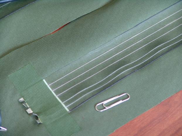
As another example, collaborative developmental work between Defense R&D Canada (DRDC) and Bennett Fleet Québec has enabled the production of a novel approach to the placement and distribution of different conducting wires with different resistivity over a textile substrate which is then covered with a semi-permeable membrane maintaining the wires in place as shown in Figure 3. This technology (called C@PS™ patent pending) consists of continuous macro encapsulation of conductive wiring ranging from 20 to 26 AWG with a semi-permeable membrane. This technique also enables the placement of conductors inside existing clothing.
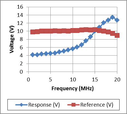
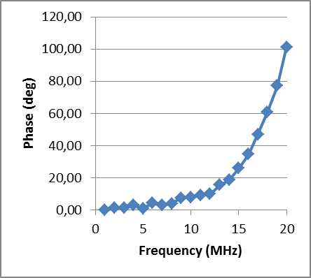
Samples of the C@PS™ technology was submitted to extensive electrical testing to determine the performance envelope. Figure 4 presents the frequency response and the phase shifting for an electro-textile sample made of a 66 Ω/m yarns. Details of the measurement setup are described in [7]. All measured samples demonstrated a frequency response that could be approximated to a linear progression below 10 MHz, and a phase shifting stable below 15 MHz At frequencies over 15 MHz, the systems responded with increased phase shift and output voltage amplitude—this response is explained by the greater importance at higher frequencies of the parasitic capacitance and inductance of the transmission line.
In addition to energy transport and data transmission, the C@PS™ technology has the potential to detect various stimuli. During the developmental phase, it was observed that the electrical characteristics wiring (such as the conductivity) varied with the environmental conditions. With the use of proper components, the electro-textile structure can detect moisture, temperature, and movement. Depending on the context, variations of stimuli can be measured and modulated, and therefore are predictable. Those properties will be further investigated and could have implication in the detection of infiltrated water in the electro-textile thus allowing proper responses to prevent electrical failure of the electro-textile system during operation.
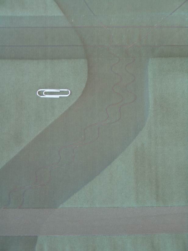
Another practical problem that had to be solved with transmission line was to go over sewing threads and seams when two adjacent textile pieces are joined together. Figure 5 shows a sample of wirings that crosses over a sealing seam (lower part of the image) as well as crossing a perpendicular set of conducting wiring without any interference. The centre of Figure 5 also illustrates that the wiring is laid in a zigzag formation in order to allow the electro-textile wires to accommodate about 5 mm of stretch of the textile at certain locations such as the elbows and shoulders. This aims at increasing the long-term reliability of the system and at reducing the variation of wire’s conductivity during movement of the user. Practically, up to 10 W of continuous power (15 W peak) could be transmitted over the standard wiring with an add-on weight budget of about 25 g per linear metre of wire. The current scheme is washable and is resistant to abrasion in normal conditions of operation.
In the current approach, it is planned to use rechargeable Li-Ion cells with a voltage range from 10–16.8 V with an average at about 15.2 V. In order to minimize power loss (or to optimize power distribution), some analysis were made about the wire size versus the voltage of the battery. From this analysis, we decided to use 22 AWG wiring to minimize loss under this voltage range (see curve). A small passive filter will be used with each battery in order to reduce overvoltage spike and reduce loss. Also, the battery that we plan to use is employing the SMBus smart battery technology to limit current output and enhance the battery lifecycle. Based on this protocol, the current will be limited at the battery level to regulate discharge. Each add-on devices on the network will also have its own power/voltage regulator to energize its own electronic component. Different power management level, such as Full power, Idle, Standby or Off, will be implemented in each devices and a user can select the state at which the device operate. In this way, the user can individually configure its system depending on the requirement of the mission.
Connector development
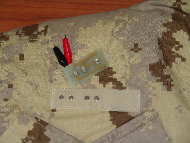
In order to interface external electronic devices to the electro-textile system, specially designed low-profile connectors must be positioned at specific locations on the combat uniform to interface with the embedded network. Durability, ability to be washed and costs were considered in the early phase of design. Development of a quick-disconnect interface based on magnetic contact and Velcro© was undertaken. Figure 6 shows one of the prototype printed circuit boards (PCB) that were constructed with small conductive magnets. Proper holes and Velcro© ties are used to make the corresponding male or female connectors. Military users found this approach interesting, but it was quickly realized that the size of this connector was critical when the number of interconnection exceeded six points. Additionally, it was found that the reliability of this approach was reduced when exposed directly to dirt and water. Nevertheless, this type of connection could be used in internal layers of clothing where the number of pins is small and exposure to the environment is limited.
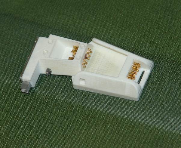
Another design approach was taken with a low snagging profile so that the interconnection would allow reliable contact. Figure 7 shows an image of the proposed male and female low-profile connector made of highly resistant injected plastic. A total of nine pins for data, energy, and ground signals are available. The current design could be expanded horizontally to allow more electrical contacts. Gold-plated, flat contact pins are horizontally inserted on the textile connector on the right of Figure 7. This approach protects the pin from direct external shock. An ‘orientation’ groove was placed in front of the pin to properly align the corresponding ‘spring-loaded’ pins of the external electronic device. A lock mechanism is included to avoid unintended disconnection of the external electronic device. As shown in Figure 7, gold-plated pins are judiciously placed to allow easy soldering of transmission lines from the electro-textile and also from external devices. This also allows to completely seal the device with epoxy, which is important in harsh military environments and to survive repetitive laundering.
Prototype uniform with combined energy and data networks
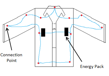
In order to simplify the wiring and to allow a certain level of redundancy and reliability, a baseline network topology was defined that includes an information exchange protocol for data and power exchange. Figure 8 shows the architecture of the electro-textile wirings, interconnections and energy pack installed inside a military shirt. Discussion with several military users have identified that the most probable location for a thin energy pack is near or under the arm pits of soldiers. In this location, an energy pack has less chance of being crushed by the weight of the soldier when crawling or snagged by external objects. Also, this location will keep the energy pack at relatively warm temperature (close to the body) when colder temperatures are encountered. As shown in Figure 8, two energy packs are placed on each side to allow a certain level of redundancy in power distribution inside the uniform. Connection points are laid at strategic locations on the uniform where possible electronic devices, sensors and communications bridges would be connected, such as in the collar of the uniform that links to the helmet. The connection points in Figure 8 are considered to be the most strategic locations to place external electronic devices and sensors. The points that are located on the torso could be used to link with other clothing layers or to the ballistic vest. The lower connection points could provide links with the pants or with other devices located on the external load carrying vest. The precise layout of connection points will have to be validated with potential users and will depend on the type of equipment to be used during operations.
As shown in Figure 8, energy packs are linked to a network of connection points that are laid in a hybrid ring and line network topology. In this configuration, data and energy are exchanged from the power source successively from one device to another and it optimizes the amount of wiring in the shirt compared to a star network topology such as USB. Instead, for this architecture, the CAN (Controller Area Network) protocol [8] was chosen because of its robust interface in noisy environments and its large support from the electronic industry. Moreover, its basic design is well suited for the proposed line/ring network topology with a non-master/slave hierarchy. At the time of writing, version 2.0 of the CAN standard is used with up to a 1 MB/s data speed which can be easily supported by current electro-textile technologies. A new version is currently under discussion with higher noise immunity, higher voltage and higher data exchange rate. Current CAN 2.0 requires a differential pair of wires for operations with terminal impedance resistors. An optional shield is recommended in noisy electrical environment.
Figure 9 shows the first prototype of an electro-textile network installed on a “2in1” raincoat. Data and power are carried from lower pockets to the upper chest pockets. Embedded conductive wirings were installed along the front opening and around the waists. Connectors were installed in each pocket to support a range of electronic devices. This prototype was used to validate concept, usability and reliability of operations with potential users before proceeding to a more extensive design.
Conclusion and future work
It is now feasible to develop reliable wearable systems that links electronic components to the textile in which transmission lines and connectors are embedded. Because the electronics are attached and detached freely, they can be protected from the physical stresses of laundering. As many different types of electronic device can be connected to any clothing, a wearable system becomes more versatile, and the user can change its functionality depending on the environment, operational context, and individual preferences. At this point, standardization (of voltage, current and connections) is the biggest challenge for wearable systems. Standardization should be done in a way that covers the multidisciplinary aspects of an e-textile as a textile, an electronic system and a computer at the same time. Another challenge is to ensure safety against potential offenses from the wearable system itself or from abusive users. For example, concerns regarding harmful effects of EMI field or leaks of confidential information must be resolved before the clothing is fielded by the users.
Future work will consist of designing and testing a full-scale wearable system (from helmet to boots) of the proposed electro-textile architecture. As much as possible, COTS components should be used to develop the prototype and appropriate diagnostics and testing tools. Textile designers and electrical system engineers will need to work as closely as possible to reach optimal designs. Prototypes should then be tested on military users in real operational conditions to validate performance as well as acceptance.
Acknowledgements
We would like to thank Ms. Isabelle Vincent, Mr. Bruno Gravel and Mr. Alain Cinq-Mars for their contribution to this project.
References
[1] Soldier System Technology Roadmap (SSTRM) Capstone Implementation Report, http://soldiersystems-systemesdusoldat.collaboration.gc.ca/ eic/site/sstrm-crtss.nsf/eng/home.
[2] M. Suh, “E-textiles for Wearability: Review of Integration Technologies”, Textile World, April 2010.
[3] M. Suh, “E-textiles for Wearability: Review of Electrical and Mechanical Properties”, Textile World, June 2010.
[4] J. Slade, et al, “Washing Electrotextiles”, Material Research Society Fall Session Symposium D3.1, Boston, 2002.
[5] http://lincolnfabrics.com/.
[6] http://www.stedfast.com.
[7] J. Dumas, and I. Vincent, “Electro-Textile Technologies for the ASAP TDP”, DRDC Valcartier Technical Report TR-2011-234, to be published.
[8] http://www.kvaser.com/en/about-can.html.
Jean Dumas is from the Québec City region in Canada and is a graduate from Laval University in electrical engineering. He has been working at DRDC-Valcartier for almost 25 years and his main R&D interest is in the use of multi-functional textiles for the reduction of the electro-optical signatures of military vehicles and personnel for the Canadian Land Forces. Jean.Dumas@drdc-rddc.gc.ca
Gaétan Demers graduated from St-Hyacinthe College in Textile Chemistry and from Laval University (Quebec City) in marketing in the 80’s. He has been a Technical Director at Consoltex Canada for 8 year and then started his own business in technical textile field in the 90’s to become specialized in the new e-textile market segment. Recently, he became the president of Bennett Fleet Quebec Inc. His vision is to develop technologies to be the worldwide leader in integrated flat electrical cable for data and/or power transmission into flexible materials (e-Textile) for wearable electronic markets. gdemers@bennett-fleet.com