
Volume 16, Number 3, November 2013
A Test Of The Acoustic Impedance Model Of Blast Wave Transmission
- 1 BTG Research, PO Box 62541, Colorado Springs, CO 80962, USA.
- 2 United States Air Force Academy, 2354 Fairchild Drive, USAF Academy, CO 80840, USA.
Abstract
The ability of armour to minimize blast wave transmission is key in mitigating blast-related injuries. The acoustic impedance model is commonly employed to estimate blast wave transmission of candidate armour materials even though the model assumes semi-infinite material thickness. The applicability of the acoustic impedance model to blast wave transmission through plates has not been experimentally verified. In this study, a 79 mm diameter, oxy-acetylene driven shock tube was used to generate a blast-like wave with a peak pressure of 1173 kPa. The pressure wave transmitted through 6.35 mm thick plates of ten different materials spanning a range of acoustic impedances was measured and compared with predictions of the acoustic impedance model. The magnitude of the peak transmitted blast pressure averaged over five trials for each material was well correlated with both the acoustic impedance of the material (correlation coefficient, r = –0.709) and with the predicted peak transmitted blast pressure (r = 0.844). However, in all cases, the acoustic impedance model predicted significantly lower peak blast pressure transmission than was actually observed, with the peak transmitted pressure varying from 9 to 90 times greater than the prediction of the model, with an average transmission of 41 times the prediction of the model. These results show that even though plate materials with higher acoustic impedance tend to transmit lower peak blast pressure, transmitted pressures are much higher than model predictions, and increasing the acoustic impedance does not ensure a decrease in peak transmitted blast pressure when selecting armour materials.
Introduction
Improvised explosive devices are commonly encountered in modern military operations, and the injury potential of both improvised and conventional explosives is well documented. Blast waves can cause injuries independently of penetrating fragments or impact injuries, and injuries attributable to the blast wave itself are called primary blast injuries [1]. Risk and severity of primary blast injuries are believed to increase with the increasing blast wave magnitude reaching the body [2–3]; therefore, decreasing the blast wave magnitude transmitted through armour materials is one goal of armour design [4].
Element-based numerical modelling of blast transmission through candidate armour designs is still in the developmental stages. Numerical modelling techniques of blast wave transmission that have been experimentally validated with a variety of materials and geometries are not yet widely available, and even when models become available, the accuracy of material properties at the very high strain rates associated with blast (~10,000/s) remain an open question. Consequently, armour designers often employ the acoustic impedance model to predict blast wave transmission through materials [4–6]. Various approaches to layering and mismatching impedances have been used under the assumption that greater impedance mismatch necessarily leads to reduced blast wave transmission and resulting injury risk [6,7].
However, the acoustic impedance transmission model assumes semi-infinite volumes of material and requires independent knowledge of the wave propagation velocity [5]. In practice, plate-based armour designs are not reasonable experimental realizations of semi-infinite volumes, and the speed of sound may not be a reasonable estimate to the shock/blast wave propagation velocity in a material. The application of acoustic impedance ideas in selection and consideration of armour materials seems to be based more in the simplicity and availability of the model than in rigorous justification and reasonable expectation of accurate predictions. To the authors’ knowledge, the accuracy of predictions based on application of the acoustic impedance model to blast wave transmission through simple plate geometries have not been experimentally verified beyond a small number of cases where blast wave transmission and resulting injury were observed to be decreased with a significant increase in the impedance mismatch [4]. The present study quantitatively tests the applicability of the acoustic impedance model for predicting transmission of air blast through materials in a simple plate geometry.
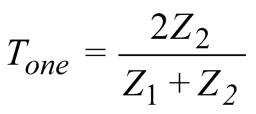
The stress wave propagation impedance in a material is the product of the material density and the wave propagation speed [4,5]. In the absence of other information, shock and blast wave speeds are often approximated by the speed of sound in a material, so that the stress wave impedance is approximated by the acoustic impedance, Z. For wave propagation normal across one plane interface of two semi-infinite media, the predicted transmission ratio, T, is:
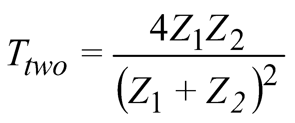
where Z1 is the acoustic impedance of the material from which the wave propagates, and Z2 is the acoustic impedance of the material into which the wave is transmitted. It is clear from (1) that the wave is perfectly transmitted in the case that the two materials have the same impedance. In the case of a wave transmitted through a material in air, the combined transmission is the product of the transmission ratios from air into the material and then from the material back into air (through two plane interfaces):
where Z1 and Z2 are the impedances of air and the intervening material, respectively.
The present study employs a laboratory scale shock tube and high speed pressure transducers to measure the blast wave transmission in air through ten different homogeneous materials of the same thickness. Results are compared with the predictions of the acoustic impedance model both in absolute terms and in terms of correlations between the acoustic impedance and predicted transmission ratios with the experimentally measured transmission ratios. It is determined that the acoustic impedance model significantly underestimates blast wave transmission through plates of material by factors ranging from 9 to 90, but that the predictions of the model are reasonably well correlated with the experimental transmission ratios (r = 0.844).
Methods
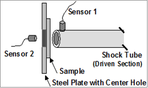
The shock tube and experimental method have been described previously [8,9]. Briefly, an oxy-acetylene driven, 79 mm diameter shock tube was used to simulate the blast waves. The shock tube was a 305 cm long piece of steel pipe. The driving section, which was filled with the fuel-oxygen mixture, was 30.5 cm long [8]. A piezoelectric pressure sensor (PCB 102B15), sensor 1, was mounted near the opening of the shock tube with its face parallel to the direction of the blast wave. Pressure sensor 2 (PCB 102B18) was placed behind the test sample with its face perpendicular to the direction of the blast wave. It was used to measure the transmitted blast wave (Figure 1). Sensor 2 was placed so that the total distance between it and the shock tube opening was 40 mm, with the sample centred in between. Given that the plates were 6.35 mm thick and were half-way between the tube opening and the sensor, the front face of the plate was 6.8 mm from the tube opening and the back face of the plate was 6.8 mm from sensor 2. The applied blast wave with peak magnitude of 1173 kPa and duration of approximately 2 ms corresponds with realistic battlefield parameters which are expected to present a significant risk of brain and lung injuries [3,4,8], while being small enough that it is reasonable to employ the sonic velocities to estimate acoustic impedances.
The test samples were 152.4 mm square by 6.35 mm thick pieces of cast acrylic, polycarbonate, aluminium oxynitride (ALON, [10]), steel, aluminium, copper, brass, magnesium, and zinc and a 304.8 mm square by 6.35 mm thick piece of tempered glass. The test materials were chosen to represent a span of impedances from ~2×10⁶ kg/m2s to ~50×106 kg/m2s. Each test sample was placed in front of the shock tube and mounted on a 304.8 mm square by 6.35 mm thick mild steel plate with a 76.2 mm diameter hole in the centre. The mild steel plate was used to minimize any influence on the pressure measurements of components of the blast wave that may have diffracted around the samples [7].
Peak transmitted pressures were recorded and pressure-time profiles were plotted for each trial. Since the peak pressure decreases with distance from the shock tube opening, the transmission ratio was calculated as the peak transmitted pressure divided by the peak unobstructed pressure at the face of the sensor, which was measured in separate trials [8]. The blast waves coming from the shock tube have a steep shock front, a near exponential decay, and a positive pulse duration of about 2 ms. Five trials were conducted for each sample tested; mean peak transmitted pressure and standard error of the mean (SEM) were computed for each sample. Acoustic impedances are computed from material properties obtained from reference literature and are given in Table 1 along with the predicted transmission ratios calculated with (2).
Results
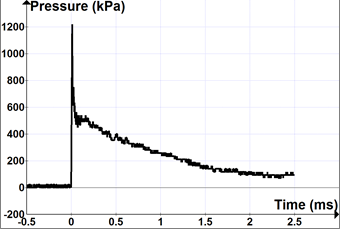
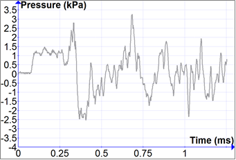
Representative pressure-time curves for the unobstructed blast wave and blast wave transmitted through a plate of magnesium are shown in Figures 2 and 3, respectively. The general characteristics of the transmitted blast wave were similar for other materials, though the peak transmitted pressures were different. Note that contrary to the expectation of Meyers [5] for transmission across a planar boundary in semi-infinite materials, transmission through a plate does not nearly preserve the original wave shape. Not only is the wave attenuated, its shape is completely different with both positive and negative pressures of comparable magnitude with the peak transmitted pressure.
| Material | Z (×106 kg/m2s) | T (measured) | T (predicted) |
|---|---|---|---|
| 6061 Aluminium (Al) | 17.4 | 3.25×10⁻³ | 7.07×10⁻⁵ |
| B36 Brass | 29.9 | 2.91×10⁻³ | 4.12×10⁻⁵ |
| B152 Copper (Cu) | 42.3 | 2.60×10⁻³ | 2.91×10⁻⁵ |
| A231B Magnesium (Mg) | 10 | 2.80×10⁻³ | 1.23×10⁻⁴ |
| A36 Steel | 47.9 | 1.39×10⁻³ | 2.57×10⁻⁵ |
| 99.997% Zinc | 29.8 | 2.39×10⁻³ | 4.13×10⁻⁵ |
| Cast Acrylic (CA) | 2.6 | 6.68×10⁻³ | 4.73×10⁻⁴ |
| Polycarbonate (PC) | 2.3 | 4.71×10⁻³ | 5.35×10⁻⁴ |
| Tempered Glass (TG) | 12.7 | 1.67×10⁻³ | 9.69×10⁻⁵ |
| ALON | 37.3 | 8.10×10⁻⁴ | 3.30×10⁻⁵ |
The experimental transmission ratio of each trial is defined as the peak transmitted pressure divided by the peak unobstructed blast pressure measured at the same location (1173 kPa). The average of five trials is shown in Table 1 and in Figure 4 for each material. The uncertainty is the standard error of the mean for the five trials.
The measured transmission ratios are much larger (by factors of 9 to 90) than those predicted by the acoustic impedance model, as shown in Figure 4 and Table 1. There is a definite negative correlation (r = –0.709, p = 0.022) between the measured transmission ratio and the acoustic impedance and a definite positive correlation (r = 0.844, p = 0.002) between the measured and predicted transmission ratios of the ten materials. A best fit empirical model for transmission ratio versus acoustic impedance is also shown in Figure 4. The model that fits the equation the best is:
where a = 6.207 and b = 1.389 are the best fit parameters. Z1 = 0.00031 × 10⁶ kg/m2s is the acoustic impedance of air at the altitude where the experiments were performed, and Z2 is the acoustic impedance of the plate material as the independent variable. The best-fit to this model had a coefficient of determination R2 = 0.716. Clearly, there is a trend of decreasing transmission with increasing acoustic impedance, but the acoustic impedance does not explain all of the observed variation in blast transmission observed in different materials.
Correlations between the measured blast transmission ratio and other material properties can also be considered. The strongest correlation of the measured blast transmission ratios is with the speeds of sound in the materials at r = –0.778 (p = 0.008). Blast transmission is not as strongly correlated with material density or elastic modulus with correlation coefficients of r = –0.443 (p = 0.200) and r = –0.747 (p = 0.013), respectively. Figure 5 shows the measured blast transmission ratio plotted against the speed of sound in each material along with a best fit function of the form:
where u is the speed of sound in the material in km/s. The best fit yields a = 0.0868, b = 1.376, and c = 0.366 km/s. It may be notable that c is close to the speed of sound in air and that the exponent b is close to that obtained in the best fit model using acoustic impedance as the independent variable.
Discussion
The results summarised in Table 1 show significant differences between the measured blast transmission and the predictions of the acoustic impedance model. This is not surprising, since plates of material 6.35 mm thick fail to satisfy the assumption of semi-infinite geometry made by the model. Using plates of finite thickness introduces several significant sources of error in predicting blast transmission with the acoustic impedance model.
The fact that shock and blast waves often have different propagation speeds from sound is a potential source of error, but the high correlation of blast transmission with the speed of sound suggests that is not a dominant source of error in this case. The high correlation of the blast transmission with the modulus of elasticity suggests that bending and flexing of the 6.35 mm thick plate contributes to transmission of the blast wave. The oscillatory nature of both the transmitted and reflected blast waves also suggest contributions from the bulk motion of the plate.
The empirical models providing best fits to the data are likely only useful for predicting blast transmission for materials of comparable thickness subjected to blast waves of comparable magnitude to the present study. If the acoustic impedance model accurately predicts blast wave transmission for material of sufficient thickness, then it would follow that plates of increasing thickness would have blast wave transmission in between the best-fit model for the 6.35 mm thick plates measured here and the prediction curve for the acoustic impedance model. In other words, as plate thickness is increased, one would expect the parameter a to become closer to 1 and the parameter b to become closer to 2 in (3). The required thickness for the acoustic impedance model to yield accurate results remains an open question, but the observation that bending and flexing likely contribute to blast wave transmission suggest that the required thickness likely depends on the magnitude of the incident blast wave and not only on the material properties.
Since armour that is so thick that bending and flexing would be negligible is likely prohibitively heavy in any application, the acoustic impedance model should be considered only as a starting point in the process of selecting armour materials to reduce blast wave transmission. Experimental data relating more directly to blast wave transmission and validated computational modelling for candidate armour materials in simple geometries are valuable and necessary to optimizing armour designs. Unfortunately, there are few, if any, computational models for which published experimental validation is available. The blast transmission data and simple geometry of the present study might provide a suitable test bed for computational approaches purporting to quantify blast wave transmission through materials.
Acknowledgements
This work was funded, in part, by the United States Air Force Academy. The authors are grateful to E.D.S. Courtney for use of the data on cast acrylic, ALON, polycarbonate, and tempered glass from an earlier study [9] and for assistance exactly replicating the earlier experimental design in the current study. The present study was motivated, in part, by comments of an anonymous referee on the earlier study [9] to consider the applicability of the acoustic impedance model to the experimental design. Comments of anonymous reviewers were also incorporated to improve the manuscript.
References
[1] I. Cernak and L.J. Noble-Haeusslein, “Traumatic Brain Injury: An Overview of Pathobiology with Emphasis on Military Populations”, Journal of Cerebral Blood Flow and Metabolism, Vol. 30, pp. 255–266, 2010.
[2] M. Courtney and A. Courtney, “Working Toward Exposure Thresholds for Blast-Induced Traumatic Brain Injury: Thoracic and Acceleration Mechanisms”, NeuroImage, Vol. 54, No. S1, pp. S55–S61, 2011.
[3] L.G. Bowen and E.R. Fletcher, Estimate of Man's Tolerance to the Direct Effects of Air Blast, Defense Atomic Support Agency #2113, AD693105, 1968.
[4] G. Cooper, “Protection of the Lung from Blast Overpressure by Thoracic Stress Wave Decouplers”, Journal of Trauma Vol. 40, No. 3, pp. S105–S110, 1996.
[5] M.A. Meyers, “Shock Wave Attenuation, Interaction and Reflection”, Dynamic Behavior of Materials, John Wiley & Sons, pp. 179–201, 1994.
[6] O.E. Petel, F.X. Jetté, S. Gtroshin, D.L. Frost, and S. Ouellet, “Blast Wave Attenuation through a Composite of Varying Layer Distribution.” Shock Waves Vol. 21, No. 3, pp. 215-224, 2011.
[7] M. Alley, Explosive Blast Loading Experiments for TBI Scenarios: Characterization and Mitigation, Purdue University, UMI Microform 1470126, 2009.
[8] A. Courtney, L. Andrusiv, and M. Courtney, “Oxy-Acetylene Driven Laboratory Scale Shock Tubes for Studying Blast Wave Effects”, Review of Scientific Instruments, Vol. 83, pp. 045111-1–045111-7, 2012.
[9] E.D.S. Courtney, A.C. Courtney, and M.W. Courtney, “Blast Wave Transmission through Transparent Armour Materials”, Journal of Battlefield Technology Vol. 15, No. 2, pp. 19–22, 2012.
[10] L. Goldman, S. Balasubramanian, N. Nagendra, and M. Smith, “ALON® Optical Ceramic Transparencies for Sensor and Armor Applications”, Surmet Company. http://www.surmet.com/pdfs/news-and-media/Surmet_ ALON_Paper_for_2010_EMWS%20final.pdf. Accessed 4 June 2012.