
Volume 16, Number 1, March 2013
An In-Air Passive Acoustic Surveillance System For Urban Threats Detection And Classification
- 1 D’Appolonia S.p.A. Largo Carlo Salinari, 18/19 – 00142 Rome, Italy.
- 2 ITTI Ltd., ul. Rubież 46, 61-612 Poznań, Poland.
- 3 University of Pannonia, Dept. Computer Science and Systems Technology, Egyetem u. 10, H-8200, Veszprem, Hungary.
- 4 Computer Technology Institute & Press “Diophantus”, N. Kazantzaki, 26504, Rio, Patras Greece.
- 5 TNO Netherlands Organization for Applied Scientific Research, Oude Waalsdorperweg 63, NL-2597 AK, The Hague, Netherlands.
Abstract
Recent military operations in urban environments are changing the requirements imposed on sensing technologies. The final goal remains threat mapping within the area of operation, but the environmental constraints and the intrinsic nature of urban threats are radically novel. AUDIS (Acoustic Urban Threat Detector for Improved Surveillance Capabilities) consists of a novel cognitive sensor that offers flexibility and adaptivity to the encountered scenarios, while also ensuring an improvement in recognition and characterization of such ground threats. AUDIS specifically aims to increase the state-of-the-art capabilities in threat detection, localization, classification and identification, supporting urban situational awareness. To achieve this goal, the novelty also resides in the sensor concept and proposed logical architecture. AUDIS exploits the conceived sparse/arrayed antenna configuration by means of an innovative ensemble of digital processing stages that support a learning-based, fully adaptive approach to urban threat recognition and characterization. The “knowledge” on the scenario and the expected/actual threats will be collected, stored and managed, exploited and grown by AUDIS to form the “base” on which the expected capability improvements can be found.
Introduction
Military forces are currently being deployed to conduct military actions, peacekeeping operations and humanitarian relief in a number of countries undergoing crisis events. As the crisis management missions evolve, a number of diverse operations are potentially conducted, which have different objectives and vulnerability levels to opponent attacks. These include (i) patrolling and inspection, (ii) secured areas monitoring, and (iii) intervention planning for relief. The common requirement of these operations is the detection and mapping of threats in the area of relevance with adequate time in advance for prompt reaction and correct decision making. The success is clearly dependent on the local scenario. In most cases, the local environment limits the mentioned operations “within the space of three contiguous city blocks” [13]. The urban environment conformation (such as the presence of alleys, shadowing buildings, and dense traffic/population) makes difficult (i) the detection of relevant targets, and, (ii) discerning between “passers-by” and “real threats”.
In addition, threats to be faced are rather uncommon: the systems should be capable of contrasting irregular, asymmetric and heterogeneous offences. Specific attention is paid to ground vehicles and human groups, potentially offensive or which have just perpetrated an offence. Surveillance capabilities should be tailored for such targets (such as low persistence time in line-of-sight, and ambiguities in detection and recognition).
These surveillance capabilities are currently supported by diverse sensor technologies to a variable degree. Systems for short/medium range area surveillance include acoustic and electro-optical (EO) sensors, infrared (IR) and magnetic sensors, and eventually radars. However, their performance is largely dependent on the observed environment, which concurs in determining the effectiveness of the “sensing domain”. The urban environment complexity is dramatically increased by the presence of neutrals (such as a crowd), the reverberation/multipath effects, the obstacles (such as buildings and trees), dense fog and light smoke-screens, which are well known degrading factors for seismic, acoustic, radar, and electro-optical sensing technologies.
To answer such problems, we developed the Acoustic Urban Threat Detector for Improved Surveillance Capabilities (AUDIS) system, based on acoustic technology for enhanced early warning and classification capabilities, including non-line-of-sight operation. Specifically, by using passive acoustic sensors, it aims to provide a remote, robust and accurate system for detecting, locating, and classifying a wide range of targets in real-time. Acoustic sensors outperform EO/IR devices, which suffer from low-coverage areas and poor visibility. Also, passive acoustic technology does not share the bistatic geometry constraints of passive coherent radars [10].
Advantages of acoustic-based sensing systems include, among others:
- They are low-cost, passive, low-power, non line-of sight, 360 degrees field-of-view, and wide area coverage.
- They provide the ability to detect-classify-localize-track a variety of transient events (such as mortar, snipers and explosions), continuous sources (such as tanks, trucks, and helicopters) and personnel.
- They can complement other sensor modalities via cueing and fusion.
In this work, we discuss the overall architecture of the AUDIS system and briefly present the functional software and hardware components used in its implementation. The AUDIS system achieves effectiveness in threat detection, localization, classification and identification; acoustic sensors cooperate with the city environment by ensuring adaptivity to the scenario and current mission objectives, extended coverage beyond and in non-line-of-sight, robustness to interferences, a multi-perspective vision, and cognitive capabilities for supporting threats discrimination in a noisy scenario.
In this paper the related work and the state of the art is first reviewed, and then the overall architecture of the system is presented, followed by the introduction of the main system components. Finally, the main features and the innovation of the proposed system are discussed.
State-of-the-art acoustic sensors for military operations
Acoustic sensors have been the leading technological solution for gunfire detection for over 20 years, having also been deployed in static locations (such as rooftops) for battlefield remote surveillance, or mounted on vehicles in order to augment the situational awareness of the crew. Pilar (US Army) [2], SADS (Sniper Acoustic Detection Sensor, by Rafael) [3], and Boomerang (BBN Technologies) [4] systems are small-size solutions for sniper detection. Larger area coverage (up to 2,000 km2) is ensured by ARTILOC (Artillery Location Acoustic System, by Rafael) [5] and HALO (BAE System) [6] systems, being very efficient in the location of mortar and artillery fire as well as identify impact points. Acoustic sensors are often integrated with other technologies in battlefield surveillance applications. The Remotely Monitored Battlefield Sensor Systems (REMBASS) II [7] uses omni-directional seismic-acoustic, infrared and magnetic sensors in small range area surveillance (less than 350 m). Ground vehicle detection capabilities have been demonstrated for stand-alone acoustic components of anti-intrusion systems (detection performance of tanks up to 1–2 km) [7]. It is worth noting that acoustic “stealth” vehicles are currently under development [11].
Acoustic-based systems are also common solutions for air surveillance, due to their “passive” nature. One such example is the RAFAEL Helispot system [8], which demonstrated good performance in the detection of helicopters flying at low altitude in ranges of tens of kilometres and without line-of-sight visibility. Moreover, aircraft flight path estimation by means of acoustic sensors is supported by signal processing advances that exploit acoustic array technologies [8]. In recent years, large networks of passive acoustic omnidirectional sensors have been efficiently tested to track aircrafts—such as the land-based acoustic surveillance research conducted by DSTO (Defence Science and Technology Organization, Australia), deducing the motion parameters from the Doppler analysis of the acoustic radiation [12].
Furthermore, acoustic wireless sensor networks have been utilised in the US DARPA project (NEST) [9] for implementing an acoustic shooter localization system, where the sensing was performed by a large distributed sensor network. The sensor elements were tiny, inexpensive devices each collecting information in their neighbourhood. The acoustic events related to shots (muzzle blasts and shockwaves in case of supersonic weapons) were detected and time-stamped by the sensors, and after sensor fusion the position of the sniper (and, in case of supersonic weapons, the direction of the shot) were detected with high accuracy.
Audis overall architecture
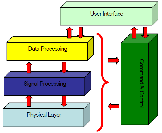
The proposed acoustic urban threat detector consists of five functional layers. These layers are designed in accordance with the AUDIS objectives—that is, to detect, localize, classify and characterize a number of diverse “acoustic” threats in an urban environment.
- The Physical Layer (PL) is the interface of the system with the real world and it is constituted by a couple of microphone arrays. The environment acoustic signals are acquired and converted into electrical signals that are elaborated in the devices belonging to the next layers. The antenna positioning is a strategic choice in order to maximize the coverage of the key infrastructures in the monitored area. Finally the design of the antenna geometry affects the overall system performances.
- The Signal Processing Layer (SP) works directly with the raw signals coming from each microphone. Those signals are intelligently combined in order to reduce the effect of the noise and interferences (maximize the signal‐to‐interferences plus‐noise ratio) by exploiting ad‐hoc signal processing algorithms (that is, beamforming techniques).
- Data Processing Layer (DP) operates on the refined signals coming from the signal processing block. At this step the signals are transformed into information on the warfare scenario. The aim of this block is to detect, track and classify potential threats (represented by ground vehicles and people) and to generate the tactical picture of the monitored scenario. This layer is also in charge of analyzing the generated picture by means of behavioural reconnaissance and threat detection algorithms to generate alarms to be provided to UI layer.
- Command & Control Layer (C2) operates as a cross‐level controller that supervises and synchronizes all the other levels. This block interprets also the user commands provided by the UI layer.
- User Interface Layer (UI) collects the information from the DP block and reproduces a digital map of the warfare scenario with the upgrading of urban environment actors (ground vehicles and people). An intuitive, user friendly interface is provided by the system for the operator.
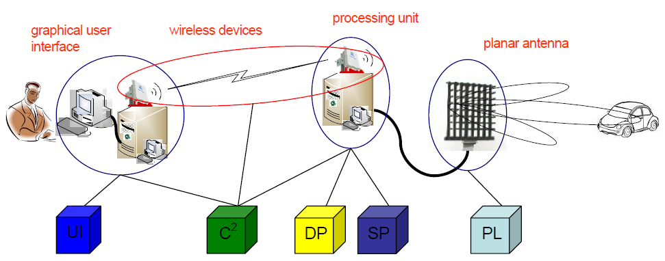
The physical architecture of the AUDIS System is constituted of the following parts:
- microphones array sensor (UAS);
- processing unit located close to the UAS;
- communications devices (such as wireless nodes); and
- graphical user device.
In Figure 3 a scheme of the physical architecture is provided, where the corresponding logical layer is also indicated for each device. The planar antenna is directly connected with a local processor, in which the SP and DP operate. The processed data are then transferred by wireless or wired devices to the end-user computer, to which the user interface layer corresponds. The data transfer rate is only related to the high level data (such as target position and class), so bandwidth requirements are very low. As mentioned above, the C2 is the cross‐level controller that is physically distributed on the different devices. Depending on logistic and practical considerations, the processing unit and the graphical user Interface can also be co‐located.
System components discussion
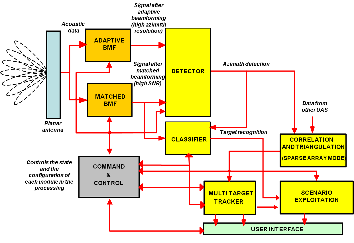
In Figure 4 the instrument flow logic is schematically represented. The components and their functionality represented in Figure 4 are the following.
Planar antenna
This component is constituted by an array of microphones. Each microphone converts the urban environment acoustic signals into electrical signals that are post‐processed. AUDIS applies the concept of Acoustic Arrays to urban situation awareness, focusing on NTTs (non-transient threats). Technological capabilities offered by arrayed configurations allow for: (i) enhanced target detection probability, (ii) volume scanning for target search, (iii) enhanced localization capabilities, (iv) target tracking along its path, (v) improved non-LOS echo rejection, and (vi) multi-functional operations.
In the AUDIS system, a 2D array antenna is used since both vertical and horizontal directivity is required. Nevertheless directivity requirements are strongly different along the two directions, making rectangular antenna shape the most appropriate solution. Rectangular shape has several advantages with respect to other shapes that are crucial for the problem at hand:
- It makes easy to handle very different directivity requirements along vertical and horizontal directions.
- The instrument is modular and easy to resize.
- Simple paths are provided to the design procedure for requirements fulfilment.
- It helps structuring the beamforming processing and properly distributing it across the antenna elements.
Beamforming techniques (matched - adaptive)
The data received from the microphones are first converted to the frequency domain by means of Fast Fourier Transform (FFT) processing. Then signal processing, based on two beamforming blocks (matched/adaptive) running in parallel, is performed.
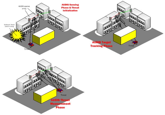
Real-time beamforming allows volume search and target tracking operations, which are essential for sensing the urban scenario and collecting information on the addressed menaces. A pictorial view of the target tracking capabilities is reported in Figure 5. Sensing phases are reported where UAS resources engagement is tailored to the current threat scenario. It is evident how multi-perspective observations are used for classification and target characterization.
The matched beamforming block operates to combine coherently the signals from the microphones for each direction with an electronic steering mechanism, which enhances signals from the direction of interest and suppresses signals from other directions. This block provides highly robust operation under non-ideal conditions as well, but the output Signal to Noise and Interference Ratio (SINR) is modest, due to high side-lobe patterns.
The adaptive beamforming block minimises all coherent contributions from other directions than the looking direction. For this purpose, adaptive filter weighting have to be determined based on the correlation matrix of the microphones data. In this way, the adaptive beamformer maximises the beam output SINR by means of minimising the total output power while maintaining a constant gain in a specified beam direction. The goal is to suppress directional noise, by adaptively changing the array weighting in such a way that the side-lobes corresponding to sound sources of non-interest are lowered under the background noise. Adaptive beamforming leads to adequate suppression of interferences but makes the signal phase information not available for further processing (classification). In the proposed logic chain the adaptive beamforming is used for detection and estimation purposes by identifying threat bearings, while the output of the matched beamformer is used in the tracker and classifier units
Detector
The detector block is the first step of the data processing layer. The aim of this unit is to decide if in a given direction a target is present or not. The decision is based on the output of the matched and adaptive beamforming. In particular the detection algorithm is based on an adaptive threshold that guarantees good performances also in a time-varying environment.
Classifier
The classifier block operates on the detector and the selected matched beamformers outputs. Its aim is to classify the target detected. The classification is based on the target acoustic signature, by correlating the features of the measured data with the features stored in the signature database. The estimation of physical parameters (such as speed of target) can provide useful information to derive the target behaviour and to help the operation of the classification stage.
Correlation and triangulation
The correlation and triangulation blocks operate only in sparse mode (when multiple arrays are present). Its aim is to fuse the information from the different antennas to have a multi-perspective view of the warfare map and to resolve the position of the targets.
Multi target tracker
The multi target tracker operates on the output of the detector and of the classifier. It is in charge of filtering the observation noise, as well as estimating and predicting the motion of the targets (that is, to track). Its output is represented by a tactical picture of the warfare scenario
Scenario exploitation
In the scenario exploitation block the behavioural analysis and the threat detection are provided, based on the class and the position/trajectory of the targets (that is, tactical picture). Track labels are produced by the AUDIS system with attributes derived from the classification stage. The identification of the threat level for a given patrol, friend building, etc is to be derived on the basis of model-based analysis and risk evaluation. When acoustic phased arrays are used yielding higher sensor directivity, multiple perspectives well support target behavioural description and prediction of intent functions (such as a stationary vehicle that switches the engine on can be detected and its subsequent movement predicted; it will be potentially harmful only if it moves towards the patrol or exhibits an anomalous behaviour, such as stop-and-go or unusual accelerations). This implies a twofold effort: (i) characterization of the urban scenario in which the target moves, and (ii) representation of behavioural models to be used for risk assessment.
The output of this block is a series of alert messages delivered to the UI, to help decision making and to activate the proper emergency protocols.
Command and control
The command and control (C2) component is a cross‐level supervisor that synchronizes all the other components. It is a substructure that switches automatically the operating modes of each block. The C2 must interpret the orders derived directly from the user, and convert them to functional instructions for each block.
The C2 is in charge of the following operations:
- configuration of the blocks (such as thresholds, algorithms parameters and settings);
- management of the blocks (such as on/off turning, fine tuning, data transfer control, and communication protocols);
- maintenance and diagnostic (such as error check on the devices); and
- synchronization.
User interface
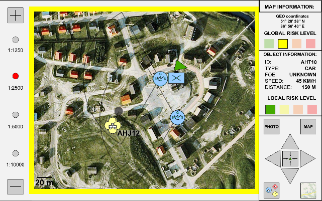
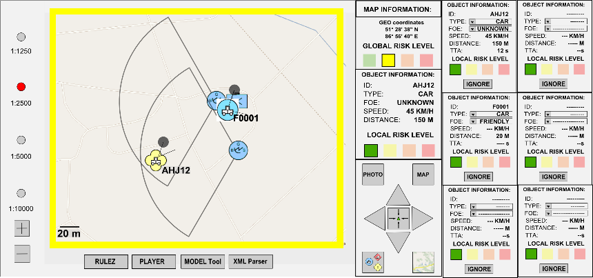
The user interface collects the information from the Multi Target Tracker and Exploitation blocks and reproduces a digital map of the warfare situation in the urban environment. In particular, the target positions are indicated on the map with the corresponding type. Moreover the warning reports, deriving from the threat analysis, are graphically represented on the screen.
In order for the Graphical User Interface to meet different user’s operational requirements, it was developed in two different versions, the Mobile Unit GUI and the Command & Control GUI. The Mobile Unit GUI acts as a viewer, responsible to visualize information, as sensor’s position and threat’s position and type. On the other hand, the Command & Control GUI is responsible to act as a bridge between the users and the system’s sub-modules, such as Multi Target Tracker and Exploitation Unit. The Command & Control GUI visualizes multiple threats information, while it interacts with end users in order to forward information to other system’s sub-modules.
Other integrated sensors
Apart from the standard microphone sensors incorporated within the array, there is a list of additional sensors that need to be integrated due to the following two fundamental reasons:
- Precise information regarding environmental parameters such as temperature, humidity, and wind conditions is needed, in order to use them in our model of the environment due to their effect on sound propagation velocity.
- Precise information regarding the placement and the orientation of the microphone arrays is needed, in order to be as accurate as possible in our steering vectors definition and targets positions derivation.
In order to measure this information, a small number of wireless sensor network nodes with integrated sensor boards are used. This is an extremely low-power solution, which can operate completely independent of the microphone array. Cost-wise it is comparable to the cost of a high-precision scientific weather station, offering the additional advantages of programmability (such as, using high-rate sampling) and ease of interfacing with other systems. Additionally, this solution is highly modular and elements that need not be present on each and every microphone array can be omitted, a feature not available in most scientific weather stations. Such sensor modules are equipped with high-quality antennas, which can enable radio communication in the range of a few hundred meters, eliminating the need for additional wiring between the arrays and on their surface.
The list of sensors placed on each microphone array is as follows:
- GPS sensor. This sensor module is required to have precise information about the placement of the array (including height).
- Accelerometer and Tilt sensor. This sensor module is required in order to take into account small movements and other changes to the orientation of the microphone array due to environmental parameters (i.e., wind). The detection process should be aware of such changes and the operator of the array should also be informed in order to act accordingly.
- Digital Compass / Magnetometer. The input from this sensor module completes the required information regarding the orientation of the microphone array.
- Temperature sensor. Since sound propagation is effected by the ambient temperature, the output of this sensor is used to tune the acoustic model.
- Humidity sensor. Similarly to temperature, humidity is used to tune the acoustic model used for the microphone array.
- Wind sensor. Wind speed must be taken into account in order to estimate the respectively caused background noise level. Also, wind speed and direction is used to estimate ‘bending’ of propagated sound waves.
System hardware components
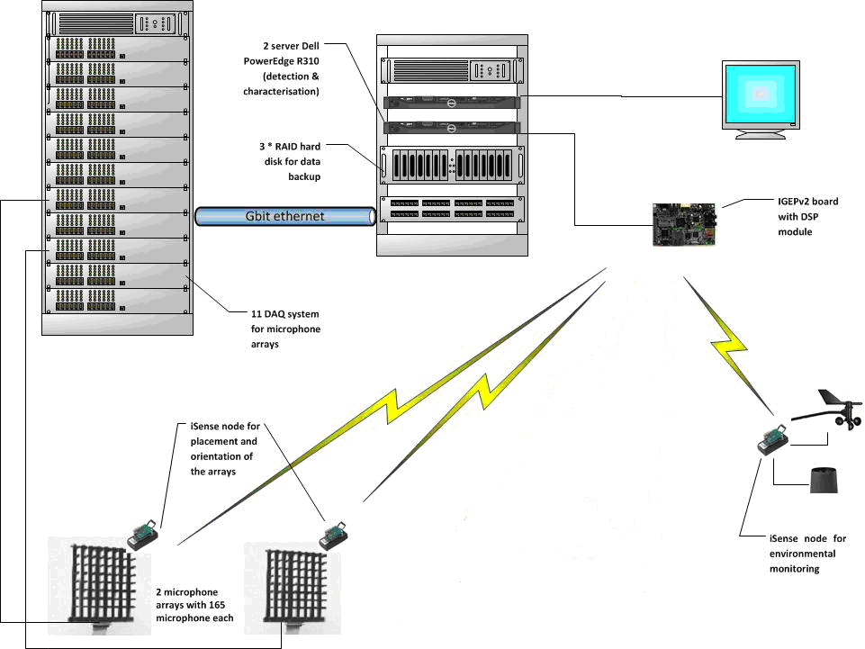
In Figure 6, an overall view of the AUDIS physical architecture can be seen. More specifically, the following fundamental components are shown:
- The rack, housing the DAQ units that sample the microphone arrays.
- A Gigabit Ethernet network connection from the DAQ units to a networking switch.
- A rack, housing the hardware for the Data Manager (can be the same one housing the DAQ units).
- A server unit, housing the processing and storage capabilities utilized for the Data Manager.
- A set of disk drives storing the information sample from the DAQ units.
- An IGEPv2 gateway station connected to the server unit.
- A set of integrated sensor components (GPS, thermometer, etc) sampling the surrounding environment, forming a wireless sensor network and using this board as a gateway to the rest of the system.
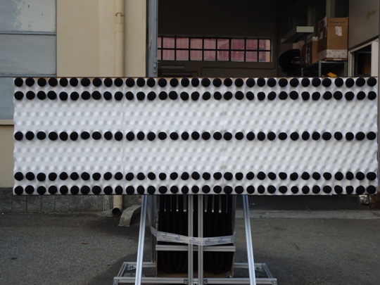
Table 1 contains the characteristics of the acoustic antennas.
The acoustic array is equipped with 165 microphones. The data acquisition unit that sample these microphones is composed of 11 capture boards, a collector board, and a server processing unit. In general, each capture board acquires the signals coming from 15 microphones placed on the acoustic array, and then provides the sampled and pre-processed signal for further processing. One of the capture cards also has the task of generating a sync signal (master acquisition board) for the remaining 10 cards (slave acquisition board). The acquisition cards communicate with the card collector through two ports (Link-port), utilizing a bandwidth of 166 Mbps each. The collector board, after acquiring data from the 11 capture boards, further processes the data and sends them to the server through an Ethernet 1000Base-T.
Each acquisition card is made of a bank of 16 pre-amplifiers followed by the same number of “ΣΔ” ADC with maximum sampling rate of 48 kHz and 24-bit resolution. The outputs of each ADC (which should ensure a simultaneous sampling) are sent to a processing unit. The signals pass through a serialization and de-serialization mechanism and through a bank of high-speed opto-couplers that provides a galvanic isolation between the analogue and digital modules. The selected DSP is a 450 MHz Sharc (ADSP21469). It can calculate an FFT (real input) of 8 k in about 120 µs. The processor is supported by 64 Mbit external RAM, which is essential to store the data before and after transformation in the frequency domain.
| Parameter | Value |
|---|---|
| Microphone Type | MPA466 TEDS |
| Microphone Noise Floor | 29 dB(A) |
| Microphone Operating Frequency Range | 20 Hz ~ 20KHz (complied with IEC 61672 Class 1 req. @ reference conditions) |
| Array Shape | Rectangular |
| Vertical Shape | 0.6 m |
| Vertical Elements Spacing | Non-Uniform (between 85 mm and 215 mm) |
| Number of Microphones in Vertical Dimension | 5 |
| Horizontal Size | 2 m |
| Horizontal Elements Spacing | 61.3 mm |
| Number of Microphones in Horizontal Dimension | 33 |
| Total Number of Microphones | 165 |
Discussion—innovation in audis
AUDIS objective is to conceive and implement a novel acoustic sensor, tailored for operations in urban environment, where a number of diverse “acoustic” threats are to be faced. Specifically, AUDIS is intended to overcome existing shortfalls in the detection, localization, classification and behavioural characterization of human beings and ground vehicles.
AUDIS goal is to fill the existing technological gaps for prompt, operational use of acoustic sensing technologies in urban warfare and peace keeping operations in urban environment
Key innovative aspects are the following:
- Arrayed configuration: array of microphones allow increased performance in target detection, enhanced spatial coverage, interference reduction (for example, reverberation in urban scenarios) and multi-tasking via adaptive beamforming of the collected echoes.
- Sparse arrayed configuration: increased beam steering capabilities and narrower antenna beams are expected to allow enhanced performance in target tracking and characterization via adaptive multi-perspective observation of the tracked NTT. Cooperative sparse modules of the array cooperate in NTT recognition within the entire area of operations.
- Multi-modal Sensor control: AUDIS sensing mode is adapted to the tracking, classification and characterization needs via real-time control of the modules, sub-arrays and antenna elements. Passive vs. active, wide vs. narrow area observation, scanning vs. fixed modes are cued by the target behaviour in analogy with bio-inspired approaches for prey sensing (such as bats).
- Multi-tasking: multiple tasks are assigned simultaneously and performed by the sensor due to the capability of forming multiple acoustic beams and processing multiple channels of data. This paves the way to area surveillance capabilities where multiple, heterogeneous threats are to be faced.
- Scenario characterization: AUDIS “learns” from the scenario itself by identifying acoustic sources and their behaviour in space and time. This allows depicting the “normal/neutral” scenario in which to search for anomalous elements (that is, initiators of potential threats).
- Threat characterization: AUDIS relies on a model-based syntactic approach for target classification, which responds to the necessity of fully representing the structures of the acoustic radiation, establishing the fundamental relationship between the target (and target behaviour) and its acoustic signature (including specific structures in the signature).
- Risk Analysis: potential threats identified by AUDIS are fully analysed in order to infer on their suspiciousness and dangerousness with respect to own forces current position and mission. The rule-based approach allows providing real time threats consolidation and verification and minimization of false alarms.
Acknowledgements
This work was supported by the AUDIS project A-0829-RT-GC that is coordinated by the European Defence Agency (EDA) and funded by 20 contributing Members (Austria, Belgium, Cyprus, Czech Republic, Estonia, Finland, France, Germany, Greece, Hungary, Ireland, Italy, the Netherlands, Norway, Poland, Portugal, Slovakia, Slovenia, Spain and Sweden) in the framework of the Joint Investment Programme on Force Protection (JIP-FP).
References
[1] T. Pham, “Advanced Concepts of Acoustic and Seismic Technology for Military Applications”, NATO Research and Technology Organisation, Technical Report, July 2010.
[2] “PILAR Sniper Countermeasure System”, November 2009, http://www.canberra.com.
[3] “SADS—Small-Arms Detection System”, January 2011, http://defense-update.com/products/s/sads.htm.
[4] J.A. Mazurek, J.E. Barger, M. Brinn, et al., “Boomerang Mobile Counter Shooter Detection System”, Sensors, and C3I Technologies for Homeland Security and Homeland Defense, IV, Vol. 5778, Proceedings of SPIE, Bellingham, Wash, USA, 2005, pp. 264–282.
[5] “Artillery Location Acoustic System—ARTILOC”, January 2010, http://www.rafael.co.il/Marketing/401-1180-en/ Marketing.aspx
[6] “Hostile Artillery Locating System—HALO”, February 2011, http://www.baesystems.com/Newsroom/NewsReleases/2005/press_11022005.html
[7] “Remotely Monitored Battlefield Sensor System-II – (REMBASS-II)”, March 2004, http://www2.l-3com.com/cs-east/pdf/rembassii.pdf
[8] C. Stubbs, M. Brenner, L. Bildsten, P. Dimotakis, S. Flatt´e, J. Goodman, B. Hearing, C. Max, R. Schwitters, and J. Tonry, “Tactical Infrasound”, Report of JASON Defense Advisory Panel, May 2005.
[9] G. Simon, M. Maróti, Á. Lédeczi, G. Balogh, B. Kusy, A. Nádas, G. Pap, J. Sallai, and K. Frampton, “Sensor Network-Based Countersniper System”, Proc. of the 2nd International Conference on Embedded Networked Sensor Systems (SenSys ‘04), ACM, New York, NY, USA, 2004, pp. 1–12.
[10] R.J. Iannuzzelli, C.E. Schemm, F.J. Marcotte, L.P. Manzi, H.E. Gilreath, J.M. Hanson, Jr., D.A. Frostbutter, A.S. Hughes, A.D. Bric, D.L. Kershner, and L.E. McKenzie, “Aircraft Wake Detection Using Bistatic Radar: Analysis of Experimental Results”, Johns Hopkins APL Technical Digest, Vol. 19, No. 3, 1998.
[11] “Shadow Reconnaissance, Surveillance, Targeting Vehicle (RST-V), July 2012. http://www.army-technology.com/projects/shadow/
[12] Clearer Radar Images of Rotating Objects, Defence Science and Technology Organization (DSTO), Vol. 2, No. 3, September 2011.
[13] C.C. Krulak, “The Strategic Corporal: Leadership in the Three Block War”, Marines Magazine, January 1999.