
Volume 16, Number 1, March 2013
Reducing The Footprint Of Deployed Information Systems With Cross Domain Solutions
Abstract
Deployed land operations across force, formation, and unit node levels typically require information systems that support multiple security domains. Each domain requires its own servers, switching, cabling, and user terminals. This infrastructure limits mobility and places significant demands on transportation, set-up time, engineering support, and field power generation systems. Thales has successfully deployed the Cross Domain Solution (CDS), from Raytheon’s Trusted Computer Solutions, aboard Royal Australian Navy (RAN) platforms and we are currently developing it for the strategic environment under the Chief Information Officer Group’s (CIOG) Next Generation Desktop (NGD) program. The CDS enables user terminals to access multiple security domains across a single distribution network, improving user efficiency and significantly reducing the infrastructure footprint. This paper introduces CDS, explains how it works and provides supporting analysis of the logistical and other benefits from adopting a CDS—compared to existing deployed LAN architectures. It also describes how CDS can be used to provide efficient access for users within the constraints of vehicle mounted C4I solutions. The reduced footprint has many benefits. These include lower overall power consumption—which in turn equates to lower generator loads and fuel consumption, reduced time to deploy with fewer devices and less cable roll out and simplified introduction of new network services to deployed users as deployment scale changes. The key benefit for Defence is that a CDS will enable essential multi-domain information systems to be deployed in the land environment in a manageable, efficient, and effective way.
Introduction
Currently a Combat Signal Regiment requires a Unimog and an 8-tonne trailer full of ICT equipment to support a brigade headquarters of approximately 50 staff. Typically, this only provides Deployed Defence RESTRICTED Network (DDRN) and Deployed Defence SECRET Network (DDSN) capability, and a handful of unclassified and DSN VoIP phones.
A typical user will have four devices on their desk, with some users managing as many as six. These include a Parakeet phone, DSN VoIP phone, DDRN laptop and DDSN laptop. If a user requires access to coalition networks or telephony, additional devices must be deployed. Each of these will need its own power supply and peripheral devices (keyboards, mice, monitors), and an individual run of network cable for connectivity.
Once the brigade arrives at a new location, there is a major cabling task to connect the servers, workgroup switches and user devices—simply due to the number of users in the command post and the required number of devices per user. These cabling activities are the most time consuming aspect of manoeuvre for the brigade headquarters and have a disproportionate effect on the number of ICT and technical staff required to support the organisation, as well as reducing the agility of the formation and reducing the ability of the headquarters to generate operational tempo.
The cabling is often bundled into groups based on the standard deployment template for the headquarters in an effort to speed up deployment times. The bundles themselves, while reducing the risk generated by tangles of unorganised cabling, are bulky, difficult to fault-find, and vulnerable to damage. They also reduce flexibility because they dictate the maximum distance between elements of the headquarters. Changing the headquarters configuration in response to threat or terrain is rendered difficult and slow.
This lack of speed in turn impacts the ability of the headquarters to exercise command and control (C2) on behalf of the commander. During the hours consumed by set-up or recovery of cabling as part of the process to enable repositioning of the headquarters, access to situational awareness and battle planning tools on the ICT networks is limited. Staff officers are forced to attempt coordination with reduced situational awareness of the battlespace during these periods, creating lulls in brigade tempo. While drills and procedures have been created to minimise these effects, they are likely to remain whilst the headquarters is constrained by these factors.
The quantity of mains-powered devices in the headquarters creates similar issues with field electrical power. The use of four to six independent mains powered devices creates a large power dependency within the headquarters. A modern deployed headquarters in the field will always have this dependency but the problem is increased in magnitude due to the large number of independent devices currently deployed. Reductions in power consumption through more efficient delivery of ICT services would lead to supply chain advantages due to reduced fuel consumption, signature reduction due to reduced thermal load, and increased agility due to reduced setup and teardown times.
Reference [1] from 2009 discusses the state of Cross Domain Solution (CDS) architectures at that time and the need for change because of the increasing reliance on information in the battlefield. We believe that many of the capabilities outlined in [1] are now available in today’s CDS—such as those described in this paper—and will effectively address the information system needs for deployed land operations.
Reference [2] from 2012 describes a cost-benefit analysis for a military use case where the CDS approach can deliver up to a 60% return on investment over three years with a total payback period of about six months.
Thales has worked with Raytheon’s Trusted Computer Solutions (RTCS) Trusted Thin Client (TTC) product extensively [4]. Thales supported its evaluation by Defence Signals Directorate (DSD) for use in Australia [5] and installed an accredited solution on HMAS SYDNEY [6]. It is currently being developed for the Chief Information Officer Group (CIOG) as a key component of the Thales solution for the Australian Defence Strategic Network under the Next Generation Desktop (NGD) program [7,8]. We understand that CIOG will flow on the positive outcomes of the NGD work to future programs.
Traditional multiple domain multiple user network
This section describes the architecture of a contemporary multiple-domain, multiple-user network and the opportunity that a cross domain solution provides.
Computer networks essentially consist of an interconnection of devices (such as computers, printers, and routers) that exchange information with each other. Typically, dedicated computer servers are used to store, process and provide shared information. User terminals enable users to process, create and otherwise benefit from the shared information. Network infrastructure, such as routers and cables, are used to provide the connectivity to distribute this information across the devices.
When users are physically distributed or need simultaneous access to the shared information, multiple user terminals and associated network infrastructure are provided to increase the usability and overall power of the computer network. In a Defence context, a unit node may have up to 25 simultaneous users, a formation node may have up to 100 simultaneous users and a force node may have up to 500 simultaneous users.
When users need access to information held at different security levels (for example, UNCLASSIFIED, RESTRICTED, SECRET, TOP SECRET) then dedicated computer networks are required for each security level. In addition, when nodes use caveats, such as AGAO, AUSTEO, COALITION and others, additional dedicated networks may be required.
As an example, Figure 1 presents the architecture of a multiple-domain, multiple-user (M×N) computer network. This architecture includes: dedicated computing infrastructure (crypto, routers, gateways, printers, and servers) to provide the back end for each of the M domains; common ICT support equipment (such as consumables, spares, and tools) that can be shared across the security domains; dedicated network infrastructure (such as routers, switching, cabling, and conduits) for the front-end network that interconnects the devices within each domain; and N user terminals (such as thin clients, laptops, and desktop) connected to each domain.
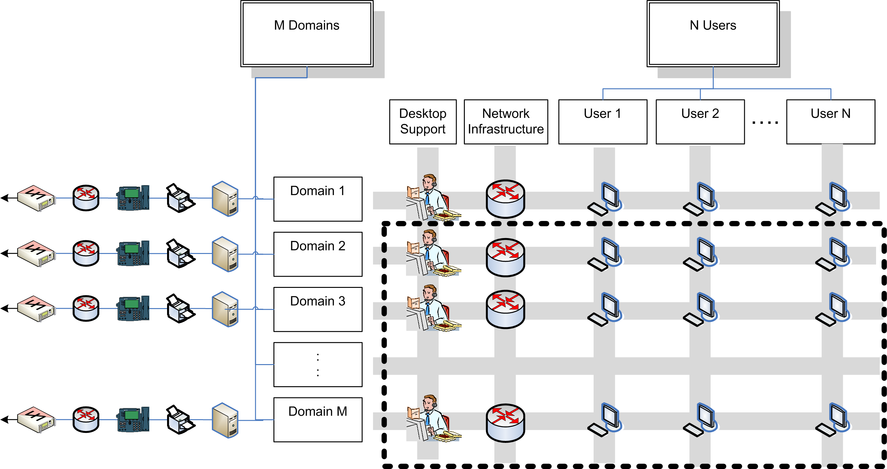
This traditional approach requires the deployment of M sets of servers and network infrastructure, M×N user terminals and at least one set of ICT support equipment. In practice, the number of concurrent domains and user terminals is bounded by cost or some physical limit such as size, weight, power and setup/tear down times (SWaP-S) and the full power of deploying a multiple domain multiple user ICT system cannot be realized. These factors will always be traded off against the typical system performance parameters such as latency and capacity.
However, with the development of mandatory access provisions and the recent availability of accredited cross- domain operating systems, a single access network can be configured to provide simultaneous access to multiple back end network domains. In this case, a single set of N user terminals and associated network infrastructure can be used to interconnect with M network domains, providing efficiency saving, ε, of:
This gives an ε of 50%, 67%, 75%, 80%, … for M = {2, 3, 4, 5, …} respectively, which enables the full power of multiple domain networks to be cost effectively realized.
The reduction in desktop support, network infrastructure and user terminals shown within the dotted line in Figure 1, is the core benefit of deploying a CDS that is quantified by Equation (1). Some environments utilize a switching mechanism, such as a keyboard, video, mouse (KVM) switch, which still requires multiple workstations at the desktop. In this type of environment, the user can only view one network at a time and the need for extraneous hardware, software, desktop administration, cabling, and power consumption still exists.
The cds architecture
This section provides an overview of the RTCS TTC component of the CDS and describes and some of its benefits.
TTC provides an enterprise-level thin-client architecture that allows end users to access common applications easily and securely across multiple domains or enclaves at different classification levels. Figure 2 shows the high-level CDS architecture with multiple backend security domains.
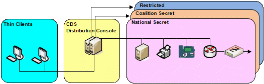
TTC is made up of three core components: the CDS thin client, the CDS distribution console server, and an accredited operating system.
The cds thin client
The CDS thin client software image provides secure, simultaneous access to applications on multiple single domain networks. The client runs on inexpensive end-user terminals such as thin-client hardware, laptops, desktops and other suitable devices. The thin client devices are flash loaded with the client software that is completely unclassified and does not store any user data. The thin client is effectively stateless, which means they remain unclassified except when displaying classified data.
In use, the thin clients register with the CDS distribution console for proper configuration at start-up and the secure access controls deny any unapproved devices the ability to participate.
The cds distribution console server
The CDS distribution console software image is the solution’s server component that provides the physical connection to multiple single domain networks whilst maintaining data separation between each network.
The distribution console is a boundary protection device that controls all client/application content networking and routing functions providing a secure gateway to each individual classified network. The CDS is very scalable where typically a single distribution console can support 300+ users and can be either used stand-alone, in parallel or clustered where redundancy, load-balancing, or a larger number (30+) of network domains is required.
The CDS distribution console software executes on standard off-the-shelf hardware albeit with separate network interfaces for each network domain (to form a back-end server network) and one network interface for the clients (to form a front-end access network).
The accredited operating system
Both CDS software images use Red Hat® Enterprise Linux® with Security-Enhanced Linux (SELinux) as the underlying operating system to provide stringent security controls and maintain the necessary network/data separation inherent in the solution. This version of Linux has been certified at Common Criteria EAL4 [3]. The system is secured using measures such as mandatory, discretionary and role based access controls as well as a type enforcement policy and label security. These access controls and the secure operating system reduce risk and allowed the technology to be certified as an approved Cross Domain Access Solution by the US Unified Cross Domain Management Office and accepted by government security agencies to be used in environments classified up to TOP SECRET with multiple compartments [3]. This baseline contributed towards the DSD evaluation activity in Australia.
The benefits
The combination of stateless thin client software, distribution console and accredited operating system provides many benefits, including:
- A single desktop for multiple security domains—less user desk space, less power consumption, lower acquisition and support costs [2].
- A single front-end access network for all security domains—reduced cabling infrastructure, quicker set-up and tear-down.
- Significantly reduced security governance overhead because laptop hard drives no longer need to be removed, signed for by serial number or accounted for monthly. This removes an enormous strain on Army units who would otherwise audit hundreds of devices across large geographical areas such as the Middle East Area of Operations.
- Enhanced security due to centralised data repositories and stateless user terminals that are classified only when displaying classified data. This reduces the threat to data confidentiality in the event a remote or mobile node is compromised.
- Flexible and powerful access control based on the user permission levels and infrastructure location. For example, a user with SECRET permissions cannot login to a SECRET domain from a thin client located at a facility that is only accredited to RESTRICTED.
- A better user experience through simplified access to multiple domains and more sustainable ergonomics.
- Rapid and flexible application deployment and management capability.
- Provides a platform for future capability enhancements such as more streamlined and controlled transfer of information between security domains.
Further details on TTC can be found in [3] that provides a comprehensive description of the technology, its features, benefits and suggested architectures.
Cds for deployed lan
Introduction
This section describes how the CDS architecture and the underlying technologies can be adopted in the deployed LAN (DLAN) environment to provide a tactical advantage to deployed forces. A description of the As-Is and proposed To-Be DLAN architectures is presented followed an analysis of the SWaP-S benefits.
The as-is dlan
The DLAN architecture currently used by the ADF consists of segregated security domains with air-gapped equipment and network cabling with fat client workstations. Figure 3 shows the current or As-Is DLAN architecture in a simplified form however, an UNCLASSIFIED domain has been included to provide a better comparison with the To-Be architecture.
Each security domain has server side equipment connected to the WAN via its own encryption devices. This equipment is usually installed in transit cases to meet environmental and transportability requirements. Each domain network is extended to user work areas, typically located at close range. In most cases, fibre optic cable is used for these network links. A workgroup switch is placed in the user work areas to support many users.
| SWaP-S Element | Node Type | ||
|---|---|---|---|
| Force | Formation | Unit | |
| Volume (m3) | 80.2 | 29.9 | 6.6 |
| Number of trailers | 4.9 | 1.8 | 2.4 |
| Weight (kg) | 18,683 | 6,973 | 1,697 |
| Power (kW) | 171.0 | 62.7 | 13.1 |
| Fuel rate (l/hr) | 57.0 | 20.9 | 5.4 |
| Set-up (pers-hrs) | 110.9 | 41.1 | 7.9 |
| Cable (km) | 15.2 | 5.7 | N/A |
| SWaP-S Element | Node Type | ||
|---|---|---|---|
| Force | Formation | Unit | |
| Volume (m3) | 21.4 | 10.7 | 3.4 |
| Number of trailers | 1.3 | 0.7 | 1.2 |
| Weight (kg) | 4,916 | 2,463 | 876 |
| Power (kW) | 43.0 | 21.0 | 6.5 |
| Fuel rate (l/hr) | 14.6 | 7.7 | 2.7 |
| Set-up (per-hrs) | 28.6 | 14.2 | 4.0 |
| Cable (km) | 3.8 | 1.9 | N/A |
Separate networks need to be laid throughout the deployment area to support multiple security domains and users have a separate access terminal for each.
A proposed to-be dlan with cds
A proposed To-Be DLAN architecture with CDS is shown in Figure 2.
Each security domain has application servers and client Virtual Machines (VM) to support the thin client environment. All the security domains are connected to the DSD evaluated distribution console. A single physical network carrying multiple domains (multiple VPNs in a single media) is then extended to the user work areas to connect the thin client terminals.
Figure 2 also shows how a mobile node can use the same infrastructure to access multiple security domains using a thin client device. The communications link will need only a single encryption device with a bandwidth of a few hundred kilobits per second, depending on the type of applications in use.
As-is and to-be dlan swap-s analysis
This section provides a summary of the space, weight, power and set-up time improvements that CDS could provide for DLAN. The analysis is based on three basic DLAN configurations for force, formation and unit nodes.
For each configuration, the SWaP-S has been determined for the workgroup equipment only—that is the switching, cabling and user laptop computers that are needed to support each security domain. The figures used for volume, weight, power, and set-up time for both the As-Is and To-Be cases are derived from the DLAN system elements currently in service with the ADF. This simplified the analysis and although the DLAN is undergoing generational changes, the workgroup equipment is likely to require the same or similar SWaP-S to the current generation.
The back-end server equipment will be subject to generational change with more powerful, compact processors and virtualisation. However, it is likely that the back-end will be similar in terms of SWaP-S for both the As-Is and the To-Be cases, so it has been excluded from the analysis.
The calculation for the number of trailers required for transportation was based on the use of medium weight trailers for force and formation and lightweight trailers for the unit nodes, considering equipment volume only.
The calculation on the hourly rate of diesel fuel consumption was based on the use of the node organic power generators assumed to be 16 kVA (5.3 l/hr) for force and formation and 2.5 kVA (1.0 l/hr) at the unit nodes.
The cable lengths were based on the fibre cable reel assemblies that are normally provided with the DLAN for force and formation nodes. These are not used for unit nodes.
The analysis scenario was simplified so that the benefits of CDS are not overstated. Deployments may need less than four security domains and every user may not need access to every domain. Therefore the analysis has been based on a scenario with four domains at the force node, three at the formation node and two at the unit node.
Table 1and Table 2 show the SWaP-S figures for the As-Is and To-Be cases respectively. Table 3 shows the dramatic reduction in each SWaP-S element using CDS.
Overall, this reduction could increase to about 75% if four domains are provisioned for each node —and increase further if more domains are added. Even if only two domains are provisioned at every node, the reduction in SWaP-S with CDS would be close to 50%. These figures align with Equation (1) showing that it can be used as a general rule of thumb for other configurations.
| SWaP-S Element | Node Type | ||
|---|---|---|---|
| Force | Formation | Unit | |
| Volume % | 73 | 64 | 48 |
| Number of trailers % | 73 | 64 | 48 |
| Weight % | 74 | 65 | 48 |
| Power % | 75 | 67 | 50 |
| Fuel rate % | 74 | 63 | 50 |
| Fuel saving in 10 days (ltrs) | 10,177 | 3,160 | 645 |
| Set-up % | 74 | 65 | 49 |
| Cable % | 75 | 67 | N/A |
Table 3 shows an example of the significant fuel saving that could be achieved over a 10-day (240-hour) deployment period with CDS. There is also the benefit of transportation fuel reductions however this was not included in the analysis.
Cds for vehicle mounted operations
Vehicle-mounted considerations
The past integration of electronic systems into vehicle platforms has been conducted in a stove pipe manner, leading to the mechanical integration of multiple and dedicated computers, servers, communications devices and displays.
This has resulted in two problems inside the vehicle:
- Inefficiency—leading to exceeding the available SWaP resources in the vehicle.
- Inflexibility—in the allocation of roles and tasks to crew members inside the vehicle and between different vehicles. Crew positions must be dedicated to specific roles or tasks and crew members can only access particular functions from specific crew positions in specific vehicles.
The proliferation of hardware devices into those vehicles, and the emergent requirement to enable separation and access to several information domains at different classification levels, has led to the demonstration of the tactical implementation of the CDS as part of the vehicle’s electronic architecture (VEA).
Tactical cds architecture
The proposed tactical CDS architecture is structured around three layers:
- Computing resources, embedded systems and data buses are segregated into separate domains based on the security level of the applications they provide and the information they are processing.
- A CDS distribution console will manage the publication of sets of application HMIs to crew members based solely on the set of credentials used to access the system. This provides the basis for universal access to vehicle functions and flexible assignment of crew roles.
- Smart displays will provide the vehicle users with a computing device that runs the CDS thin client within a virtual machine (VM). This allows users to switch from any dedicated local applications to remote or network based processing using the VM to access the required multiple domains.
Comparison with legacy c4i systems
The proposed tactical CDS solution approach for vehicle platforms provides several important innovations compared to legacy systems:
- The amalgamation of computing resources into a multi-level and integral computing infrastructure.
- A single standardised crew display with interaction through a set of bezel buttons and touch screens.
- Simplifies the implementation of a ‘universal’ data bus ensuring the convergence of all voice, data, video, and platform-generic services over IP.
- A secure CDS infrastructure ensuring physical separation between information domains at different security levels, strict user access control, and other security controls where appropriate.
- A smooth transition between the deployed computing environment and on-the-move and in-the-vehicle computing for military end-users.
- Software application deployment that is independent of the roll out of new/upgraded hardware components.
Limitations and work in progress
The tactical CDS currently proposed is being further investigated to address additional requirements inherited from real time, embedded and safety critical systems. The integration of these requirements into the final solution is likely to require the hybridisation of the vehicle-borne CDS architecture with other technologies to cost effectively minimise the SWaP demands of the back-end components of the VEA.
Conclusion
This paper set out to discuss the benefits to the Australian Defence Force (ADF) of using the CDS approach. The CDS has proven itself to be eminently suitable for ADF applications that require multiple security domain computer networks through the existing deployments aboard RAN platforms. This is flowing through to the strategic environment where the NGD solution development is well underway.
This paper has described the key benefits that CDS would provide for the future generation DLAN and vehicle mounted operations. The reduction in SWaP-S for the DLAN workgroup equipment is striking—with, for example, a 75% reduction for a four-domain node. Given the sheer logistics involved with major deployments at force, formation and unit levels—and the equipment constraints within a military vehicle—it is likely that the CDS approach delivers the only realistic means to access multiple security domains from a single user device.
It is recommended that requirements covering the benefits of CDS architecture are considered for inclusion in the definition of future ADF communication and information systems where multiple security domains may be required. This will help meet cost reduction targets as well as provide a wide range of operational and logistic benefits.
References
[1] K. Plyler, B. Tague, R. Thomas, and S. Tsang, Tactical Cross Domain Solutions: Current Status and the Need for Change, IEEE 978-1-4244-5239-2/09, 2009.
[2] S. Parks, The Total Economic Impact of Raytheon Trusted Thin Client, Forrester Consulting, 2012.
[3] Trusted Thin Client—Secure Access to Multiple Domains from a Single Connection Point, Raytheon Trusted Computer Solutions publication 800.230.1307, 2012.
[4] G. Kamis and P. Feighan, “Enabling Mission Readiness Through Cross Domain Solutions”, MILCIS 2010, Canberra, 9–11 November 2012.
[5] Security Risk Assessment for Cross Domain Solution, Evaluation Report DSD 2008/1100 (RESTRICTED).
[6] Provisional ICT Accreditation 2949 for CDS – Cross Domain Solution for HMAS Sydney, CIOG TN3657, December 2011.
[7] Defence Next Generation Desktop Project, CIOG 198/10, November 2011.
[8] L. Tay, “Defence Approves Thales Next Gen Desktops”, itNews, July 2012.