
Volume 15, Number 3, November 2012
Dynamic Response Of Steel-Sand Composite Stiffened Plates Under Impulsive Loading
- * Department of Civil Engineering, Indian Institute of Technology (IIT) Delhi, New Delhi - 110 016, India.
Abstract
The present study focuses on the effectiveness of steel-sand composite stiffened plates under impulsive loading. Dynamic response of steel-sand composite stiffened plates, with various stiffener layouts under impulsive loading is analysed using commercially available finite element software Abaqus/Explicit. The steel plates and stiffeners are modelled using shell elements and the effect of strain rates is incorporated through Johnson-Cook (J-C) material model. Sand is modelled as a continuum between the two steel plates. Sand response is simulated using the built-in Drucker-Prager plasticity model in Abaqus considering the strain rate effect. The contact planes between sand and the steel plates are modelled using the general contact formulation in Abaqus. Impulsive load is applied in the form of a rectangular uniform pressure pulse. The effect of different thicknesses of the sand layer in response mitigation has been investigated. The steel-sand composite stiffened plates exhibit lesser central point displacement under impulsive loading as compared to when no stiffeners are provided.
Introduction
Development of resilient civil infrastructure requires that the structures can efficiently and economically resist unanticipated loads, and can be brought back to functionality with minimum repair and within a reasonable time if subjected to extreme events. An unanticipated load on a civil infrastructure can be caused by human activities such as blast. Due to blast, structures are subjected to impulsive loading. In order to safeguard civil engineering facilities under such impulsive loads, it is necessary to incorporate shock absorbing materials in civil engineering constructions through sandwich or composite structural framework. The sandwich structures are the emerging protective structures composed of stiff face-sheets made up of steel or concrete filled with metallic or non-metallic foam or sand in between the face-sheets. The strong and stiff face-sheet bears in-plane loads and transverse bending stress, whereas the core adds to the shear rigidity along the planes perpendicular to the face-sheet. The composite structures dissipate large amount of energy by plastic deformation under impulsive loading.
To date different materials have been explored to be used as the inner core of a composite structure for response mitigation such as fibre reinforced polymer (FRP) composites, polymeric foams, and metal foams to name a few [1]. Many researchers have studied the performance of composite plates with metallic or non-metallic foam cores in design of structures [2–5]. Qiao et al [6] have mentioned the use of sand core in composite plates and in reinforced concrete barrier structures to mitigate blast response. The easy availability and low-cost of sand as compared to metallic and non-metallic foams, and the energy dissipation capability of sand through friction makes sand a suitable choice for response mitigation against impulsive loads. However, in the literature, studies on sand core composite stiffened plates for impulsive response mitigation have not been attempted. Therefore, it is of utmost importance to study the performance of sand core composite stiffened plates for impulse response mitigation.
The objectives of the present study are: (i) to model steel-sand composite plates with and without stiffeners under impulsive loading; (ii) to study the stress, deformation, strain energy and kinetic energy response of the steel-sand composite plates for different sand layer thicknesses (ts) and stiffener configurations; and (iii) to compare the deformation results obtained from steel-sand composite plate analyses with the results obtained from analysis of steel plate under impulsive loading.
In the present study, three-dimensional (3-D) dynamic analyses of steel-sand composite structures under impulsive loading have been performed using commercially available finite element (FE) software Abaqus Version 6.11 [7]. Sand response has been simulated using a strain rate dependent Drucker-Prager plasticity constitutive model. The steel plates and stiffeners are modelled using strain rate dependent Johnson-Cook (J-C) material model. The explicit dynamic analysis procedure in Abaqus has been used. Parametric sensitivity studies are performed by varying (i) sand layer thicknesses (ts) and (ii) stiffener configurations.
Steel and sand constitutive models
Impulsive loading from blast on steel and sand can give rise to very high rates of strain (102 to 104/sec). In order to take the strain rate dependent stress-strain response of steel into account, the analysis is carried out using strain rate dependent Johnson-Cook (J-C) model [8-9]. The J-C model is a visco-plastic empirical model that depicts the effects of strain hardening, strain rate sensitivities and temperature softening. In the present study, the strain rate effects have been included by adjusting the dynamic yield stress, σ according to the J-C model as follows:
(1)
where is the dimensionless plastic strain rate at reference strain rate = 1/sec, is the equivalent plastic strain rate, is the homologous temperature, and m is a material constant. However, temperature dependence has not been considered in the present study.
The sand core is considered to follow the built-in Drucker-Prager material model in Abaqus with strain rate dependent hardening. The yield surface, F of Drucker-Prager model is given by:
(2)
where is the deviatoric stress , is the deviatoric stress tensor, is the mean stress [= (σ'1+σ'2+σ'3)/3], K is a scalar parameter that determines the shape of the yield surface and maintains the convexity of the yield surface in the deviatoric (π) plane, and r is the third invariant of the deviatoric stress tensor. The parameter β is related to the angle of internal friction, φ at the stage of no dilatancy (the critical state of sand) using the following correlation:
(3)
and d is the hardening parameter related to cohesion, c through the following correlation:
(4)
For sands, the cohesion (c) is considered to be zero. The plastic potential surface, GP of the model is given by:
(5)
where is related to the dilatancy angle, of sand as follows:
(6)
A non-associated flow rule is considered in the present analysis by considering the dilatancy angle of sand to be different from the friction angle.
Finite element model and analysis
In the present study, 3-D explicit dynamic analyses of steel-sand composite plates under impulsive loading have been performed using commercially available FE software Abaqus. Square steel-sand composite plates of size 2 m × 2 m are considered. Figure 1 shows a typical steel-sand composite plate with stiffener.
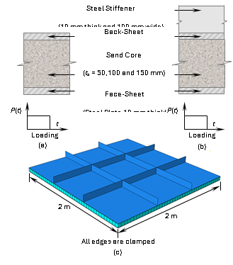
The composite plate consists of face-sheet and stiffened back-sheet with a sand core in between. The thickness of face-sheet (tfs) is 10 mm and the thickness of back-sheet (tbs) is 10 mm. The impulsive load is applied on the face-sheet.
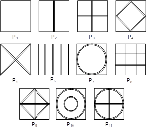
Ten different stiffener configurations have been chosen for the steel back-sheet. Figure 2 shows one unstiffened steel-sand composite plate (P1) and the stiffened steel-sand composite plates with ten different stiffener configurations (P2 to P11). The composite plates P2 to P11 are arranged as per their increasing weights. The stiffeners are 100 mm in width and 10 mm in thickness for all the configurations and with the same material as that of the face- and back-sheets. The description of the model, loading, boundary and contact conditions, material properties, analysis steps and solution scheme used are described in the following sections.
Finite Element Model
The FE models of stiffened steel-sand composite plates are developed using three dimensional part option. The extruded shell base feature available in Abaqus has been used to create geometry of the face-sheets and back-sheets. A 3-D part with solid feature is used to define the sand core. Stiffeners are created by adding an extruded shell feature implying perfect connection without any additional constraint. Care is taken not to overlap the material of the stiffener with the back-sheet by offsetting its reference surface from mid-surface, thus avoiding the possibility of additional stiffness at the junction. The back-sheet with stiffeners is created by removing material from a thick blank. It is a single part and meshed in one part only, thus implying a single part without any weld or joint/interface between the plate and stiffener.
| Parameter | Symbol | Values |
|---|---|---|
| Density | ρ | 1800 kg/m3 |
| Modulus of elasticity | E | 50 MPa |
| Poisson’s ratio | ν | 0.3 |
| Friction angle | φ | 30° |
| Dilatancy angle | ψ | 10° |
| Yield surface shape parameter | K | 0.8 |
| Initial yield strength of sand | σy | 100 kPa |
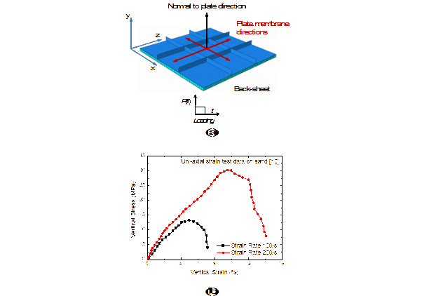
The steel plates along with the stiffeners have been modelled with four-node, linear shell elements with reduced integration, hourglass control and finite membrane strains (S4R). The sand core has been modelled with eight node linear, hexagonal, reduced integration elements with hourglass control (C3D8R). First-order elements are used because of their lumped mass formulation, which are preferred to model the effect of stress waves than the consistent mass formulation used in the second-order elements [5]. A key figure of the steel-sand composite plate is presented in Figure 3(a). All four sides of the steel plates and sand core are restrained in x, y and z directions. The interface between the steel plates and sand are modelled using frictional contact and the general contact algorithm in Abaqus. A coefficient of friction of 0.5 is assumed at the steel-sand interface.
Sand and Steel Material Properties
The stress-strain response of sand is modelled using Drucker-Prager material constitutive law. The elastic and rate independent elasto-plastic material properties assumed for sand are given in Table 1. The strain rate dependent Drucker-Prager hardening curves for sand under uniaxial compression are obtained from Jackson et al. [10]. Figure 3(b) shows the vertical stress-strain plot for sand at 100/sec and 200/sec strain rates. The stress-strain curves are converted into true stress-logarithmic plastic strain according to Abaqus/Explicit manual.
The face-sheet and stiffened back-sheet are made of mild-steel with Young’s modulus, E = 210 GPa, Poisson’s ratio, ν = 0.3 and density = 7800 kg/m3. The static yield stress of the plate material is 300 MPa. The stress-strain curves for steel obtained from mechanical testing are converted into true stress and logarithmic plastic strain according to Abaqus [7]. The material constants are obtained from mechanical testing and adopted herein for strain rates of 50/sec and 100/sec respectively as, (1) A = 375 MPa, B = 600 MPa, n = 0.07, C = 0.09; and (2) A = 360 MPa, B = 635 MPa, n = 0.114, C = 0.075. These values are computed based on tensile test data of the material as per the J-C model by neglecting the temperature effects [5].
The impulsive load is simulated in the present FE models by applying uniform pressure load with magnitude of 0.7 MPa and duration of t = 15 ms on the plate area.
Solution Scheme
The analyses have been performed in a single step, for total duration of 25 ms using the dynamic explicit procedure in Abaqus. Abaqus performs dynamic analysis using explicit central difference integration scheme. The method is conditionally stable for time increments (Δt) that are smaller than Courant time limit, Δt ≤ l/c, where l is the smallest element dimension and c is the speed of sound wave in medium in which it travels. Also, the artificial bulk viscosity is activated to properly represent propagation of the induced compressive stress wave by employing quadratic and linear functions of volumetric strain rates with default values of 1.2 and 0.06, respectively [7].
Results and discussions
Figure 4 shows the first fundamental frequency of the unstiffened (P1) and the stiffened (P2 to P11) plates determined through modal analysis using linear elastic material properties for steel. The results have been plotted for fixed and simply supported (SS) single plate with tfs = 20 mm and composite plates with tbs = 10 mm and tfs = 10 mm. For the composite plates, results have been plotted for both frictional (coefficient of friction = 0.8) and smooth contact interfaces. Higher frequency is observed for 20 mm fixed plate and fixed and simply supported composite plates with frictional contact as compared to 20 mm simply supported plate and composite plates with smooth contact. In order to check the validity of the results, Figure 4 also compares the first fundamental frequency of the unstiffened 20 mm thick plate with the analytical solution given by Rao [11]. It is observed from the plot, that the frequency values computed using the finite element analysis are in close agreement with those calculated using the analytical solution [11].
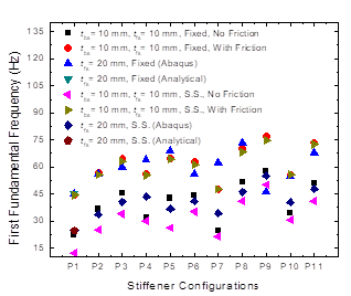
Figure 5(a) shows the peak displacement of the back-sheet central point in the direction normal to the plane of the sheet. The results have been plotted for steel-sand composite plate without stiffener (P1) with 50, 100 and 150 mm sand layer thicknesses and two plate thicknesses: (a) tfs = tbs = 5 mm and (b) tfs = tbs = 10 mm. Moreover, results are also presented for the stiffened steel-sand composite plates (P2 to P11) with 50, 100 and 150 mm sand layer thicknesses. Also, the displacement response of stiffened and unstiffened steel plates without sand core with different cases of tbs have been plotted for comparison purpose. Table 2 summarizes the peak central point displacement values for the composite plates with tfs = tbs = 10 mm and the non-composite plate with tbs = 10 mm and the percentage reduction in impulse induced displacement when tbs = 10 mm.
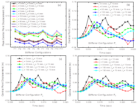
It is observed that the steel-sand composite plates with tfs = tbs = 10 mm always show more than 20% displacement reduction as compared to the non-composite plates when tbs = 10 mm. Displacement reduction is more for 150 mm sand layer thickness as compared to the 50 and 100 mm sand layer thicknesses for both 5 mm and 10 mm thick face- and back-sheets due to increased dissipation of energy in thicker sand layers. For non-composite plates with tbs = 20 mm, lower displacement is observed as compared to the composite plates which is attributed to their higher stiffness and lower mass. Thus, non-composite plates show better performance under impulse which is on the contrary to the recommendations of using steel-sand composite plates [6] as protective structures under impulsive loading. However, for structures in which slightly higher displacement under impulsive loading is admissible, use of steel-sand composite plates can reduce the amount of steel usage significantly. In all the cases presented in Figure 5(a), lowest displacement is observed for P9 and highest displacement is observed for P1. The plate P8 also shows considerably less displacement. Hence, in the present study, focus is on the displacement, stress and energy response of P1, P8 and P9 plates and tfs = tbs = 10 mm. Similar trend in results is observed for steel-sand composite plates with tfs = tbs = 5 mm.
Figure 5(b), (c) and (d) show the displacement time-history plots for P1, P8 and P9 for different sand layer thicknesses and without sand layer. Also, the displacement response of stiffened and unstiffened steel plates without sand core with different cases of tbs have been plotted for comparison purpose. For the plates without sand layer, two distinct peaks are observed in the displacement time-history plots. On the contrary, the composite plates show dissipation of plate displacement after the first peak. In general, higher displacement is observed for unstiffened plates as compared to the stiffened plates owing to their lower stiffness.
Figure 6(a) and (b) show the membrane stress time-history in the back-sheet for composite plates P1 and P8 with 50, 100 and 150 mm sand layer thicknesses. In plate P1, higher stress is observed in the back-sheet in case of 150 mm thick sand layer as compared to 50 mm thick sand layer because, in the absence of stiffeners, higher plastic strain is observed in steel for 50 mm sand layer thickness. It is observed that the octahedral plastic strain (PEEQ) magnitudes are 0.0043, 0.0038 and 0.0033 respectively for 50, 100 and 150 mm sand thicknesses at the time instance when peak stress is experienced. Thus, the octahedral plastic strain reduces with increasing sand core thicknesses. In plate P8, the peak stress values are observed to be nearly the same for all layer thicknesses because plastic strain generates in sand layer and the layer transfers the stress to the steel back-sheet.
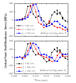
However, the peak stress reaches at a later time for higher sand layer thickness. The stresses dissipate faster in 150 mm thick sand layer as compared to 50 and 100 mm thick sand layers. Thus, the stresses in sand core dissipate faster in thicker layers as compared to thinner layers.
| Plate | Peak Central Point Displacement (mm) of Back-Sheet with tbs = 10 mm | Response Reduction (%) with Respect to Steel Plate without Sand Layer | |||||
|---|---|---|---|---|---|---|---|
| Sand Layer Thicknesses (mm) | Sand Layer Thicknesses (mm) | ||||||
| 0 | 50 | 100 | 150 | 50 | 100 | 150 | |
| P1 | 97.0 | 71.5 | 70.3 | 68.7 | 26.24 | 27.53 | 29.13 |
| P2 | 86.5 | 65.5 | 64.0 | 62.2 | 24.23 | 26.02 | 28.10 |
| P3 | 77.1 | 60.6 | 59.1 | 57.2 | 21.39 | 23.32 | 25.77 |
| P4 | 86.1 | 65.4 | 64.5 | 62.8 | 24.01 | 25.05 | 27.04 |
| P5 | 80.8 | 60.3 | 58.9 | 56.5 | 25.36 | 27.09 | 30.10 |
| P6 | 77.2 | 61.4 | 60.4 | 58.3 | 20.51 | 21.80 | 24.58 |
| P7 | 95.5 | 68.8 | 68.6 | 66.6 | 27.92 | 28.17 | 30.22 |
| P8 | 75.7 | 58.5 | 57.3 | 55.0 | 22.68 | 24.23 | 27.35 |
| P9 | 68.6 | 54.6 | 52.7 | 50.3 | 20.45 | 23.23 | 26.73 |
| P10 | 85.4 | 66.2 | 65.7 | 63.6 | 22.49 | 22.99 | 25.46 |
| P11 | 76.0 | 57.4 | 56.5 | 54.3 | 24.49 | 25.70 | 28.61 |
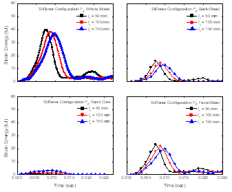
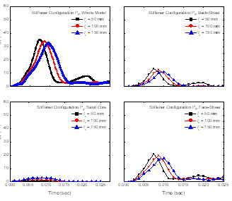
Figure 7 through 9 present the strain energy time-histories for plates P1, P8 and P9, in total as well as each of their components, that is, the face-sheet, the sand core and the back-sheet. Higher strain energy is experienced in the unstiffened plate as compared to the stiffened plates. In plate P1, the strain energies in the face- and the back-sheets are nearly the same and the values are higher as compared to the strain energy in the sand core. For the stiffened plates P8 and P9, maximum strain energy is experienced in the face-sheet followed by the back-sheet. The strain energy in sand is minimal as compared to the same in the steel face- and back-sheets. It is observed from the analysis that the stresses generated in the sand layer are almost two orders of magnitude less than the same generated in the steel plates. Thus, the lesser strain energy experienced in the sand core can be attributed to the lower stress generated in sand as compared to the steel sheets.
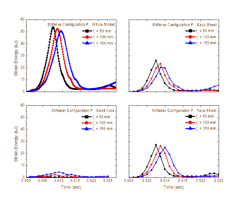
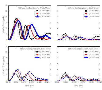
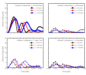
Figure 10 through 12 present the kinetic energy time-histories for plates P1, P8 and P9, in total as well as each of their components, that is, the face-sheet, the sand core and the back-sheet. Similar to strain energy, the kinetic energy is higher in the unstiffened plate as compared to the stiffened plate. For composite plate P1 with 100 mm thick sand layer, the maximum velocity values perpendicular to the plane of the plate for the centre points of face-sheet, sand-core and back-sheet are 18.2, 18.8, and 17.2 m/sec, respectively.
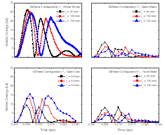
For composite plate P8, the corresponding velocity values are 15.2, 14.7, and 14 m/sec for the centre points of face-sheet, sand-core and back-sheet. For composite plate P9, the velocity values are 10.8, 11.2, and 11 m/sec. Hence, higher kinetic energy in the unstiffened plates can be attributed to higher velocity of the unstiffened plates. Higher kinetic energy is observed in 150 mm thick sand layer as compared to the 50 mm and 100 mm thick sand layers. The kinetic energy is higher in sand core than the face-sheets and the back-sheets because the total mass of sand is higher than the individual masses of face-sheet and back-sheet.
CONCLUSIONS
The present study focuses on the effectiveness of steel-sand composite stiffened plates under impulsive loading. Dynamic response of steel-sand composite stiffened plates, with various stiffener layouts under impulsive loading is carried out using commercially available finite element software Abaqus/Explicit. The effect of different thicknesses of the sand layer in response mitigation has been investigated. The following conclusions are arrived at from the study.
- Higher displacement is observed for unstiffened plates as compared to the stiffened plates owing to their lower stiffness. The lowest central point displacement is observed for P9 (that is, with stiffeners) and the highest central point displacement is observed for P1 (that is, without stiffener). The steel-sand composite stiffened plates exhibit lesser central point displacement under impulsive loading as compared to when no stiffeners are provided.
- The octahedral plastic strain reduces with increasing sand core thicknesses. The stresses in sand core dissipate faster in thicker layers as compared to thinner layers.
- Higher strain energy is experienced in the unstiffened plate as compared to the stiffened plates. The kinetic energy is higher in the unstiffened plate as compared to the stiffened plate.
- In plate P1, the strain energies in the face- and the back-sheets are nearly the same and the values are higher as compared to the strain energy in the sand core. For the stiffened plates P8 and P9, maximum strain energy is experienced in the face-sheet followed by the back-sheet. The strain energy in sand is minimal as compared to the same in the steel face- and back-sheets.
- The stresses generated in the sand layer are almost two orders of magnitude less than the same generated in the steel plates. Thus, the lesser strain energy experienced in the sand core can be attributed to the lower stress generated in sand as compared to the steel sheets.
References
[1] G.S. Langdon, G.N. Nurick, M.Y. Yahya and W.J. Cantwell, “The Response of Honeycomb Core Sandwich Panels with Aluminium and Composite Face Sheets to Blast Loading”, Journal of Sandwich Structures and Materials, Vol. 12, No. 6, 2010, pp. 733–754.
[2] S. Guruprasad and A. Mukherjee, “Layered Sacrificial Claddings under Blast Loading Part -I Analytical Studies”, International Journal of Impact Engineering, Vol. 24, No. 9, 2000a, pp. 957–973.
[3] S. Guruprasad and A. Mukherjee, “Layered Sacrificial Claddings under Blast Loading Part -II Experimental Studies”, International Journal of Impact Engineering, Vol. 24, No. 9, 2000b, pp. 975–984.
[4] X. Qiu, V. S. Deshpande and N. A. Fleck, “Finite Element Analysis of the Dynamic Response of Clamped Sandwich Beams Subject to Shock Loading”, European Journal of Mechanics - A/Solids, Vol. 22, No. 6, 2003, pp. 801–814.
[5] M. D. Goel, V. A. Matsagar, S. Marburg and A. K. Gupta, “Comparative Performance of Stiffened Sandwich Foam Panels under Impulsive Loading”, Accepted for publication, Journal of Performance of Constructed Facilities, ASCE, 2012.
[6] P. Qiao, M. Yang and F. Bobaru, “Impact Mechanics and High-Energy Absorbing Materials: Review.” Journal of Aerospace Engineering, ASCE, Vol. 21, No. 4, 2008, pp. 235–248.
[7] Abaqus User’s Manual, Version 6.11. Dassault Systèmes Simulia Corporation, , 2011.
[8] G.R. Johnson and W.H. Cook, “A Constitutive Model and Data for Metals Subjected to Large Strains, High Strain Rates and High Temperatures”, in Proceedings of 7th International Symposium on Ballistics, Hague, Netherlands, 1983, pp. 541–547.
[9] G.R. Johnson and W.H. Cook, “Fracture Characteristics of Three Metals Subjected to Various Strains, Strain Rates, Temperatures and Pressures”, International Journal of Fracture Mechanics, Vol. 21, 1985, pp. 31–48.
[10] J.G. Jackson, B. Rohani and J.Q. Ehrgott, “Loading Rate Effects on Compressibility of Sand”, Journal of Geotechnical Engineering Division, ASCE, Vol. 106, No. 8, 1980, pp. 839–852.
[11] J.S. Rao, Dynamics of Plates, Narosa Publisher, New Delhi, 1999.