
Volume 15, Number 3, November 2012
Component Penetration Kill Criteria Simulations
- * FOI, Swedish Defence Research Agency, SE-164 90 Stockholm, Sweden.
Abstract
Vulnerability/lethality (V/L) tools used to assess weapons effects in targets often need some kind of rule to assess the status of each vital component being hit. The target functionality on a system level can then be decided, based on the components that are functional as opposed to non-functional (killed). Rules of this kind are often referred to as component kill criteria. Descriptions of criteria and methods of how to assess them are rare in scientific journals, probably due to economic values, classified V/L tools, as well as classified input data to the tools. This paper presents the results from an attempt to define the penetration kill criterion of a relay via simulations. The result is compared with previously published experimental results and the methodology is discussed. Despite some shortcomings in tools and methodology it is believed that simulations can, to a large extent, be a successful way to define kill criteria for components since experimental studies will rarely be feasible due to the cost.
Introduction
Vulnerability and lethality (V/L) tools are used to assess or estimate the effects of a weapon in a target. The results are normally presented as probabilities of target incapacitation. These results are often referred to as kill probabilities or Pk—such as M (mobility) kill, F (fire power) kill, and K (catastrophic) kill [1]. The number of kill types and the true meaning of them vary in the various tools, which may cause interpretation problems.
V/L-tools that model the target on a component level require some kind of rule to assess the status of each vital component after the hit. Depending on the type of tool the status can be described as kill or no-kill for codes that run several Monte Carlo cycles in a simulation to get an average result or a probability of component kill for codes that give the result after just one simulation.
Xiangdong et al [2] formulated a definition of damage criterion when stating that “the damage criterion is a judgement that is used to determine whether a component is damaged”. They continue by stating [2]: “According to the definition of the damage criteria of components, the damage criteria include two meanings. One is the definition of damage. Another is the relation between the damage degree of component and damage elements, which act on the component”. Ball [3] describes component damage as: “The inability of a component to provide the function(s) it was designed to provide is referred to variously as a component dysfunction, damage, failure, fault or kill depending upon the type of analysis being performed and the performing organization”. Obviously there is no standardized terminology. This is further emphasized by Driels [4] who describes the kill probability as function of impacting fragment velocity and mass; “fragility curve”.
Regardless of the type of V/L-code, there can be thousands of components in a target which all requires this kind of information, for all weapon effects (such as penetration, pressure, acceleration, and heat) that the code handles. Unfortunately this information is often limited or even unavailable [5]. There are a few published scientific papers that acknowledge this problem by Putzar et al [6] and Schäfer et al [7] but they are focusing on space debris impact, and thus a high-velocity regime.
One possible way of obtaining the probability of component damage with respect to different kinds of loads is to simulate attacks on them, in the same manner as regular V/L-simulations. This is a way to overcome the problem with the high cost of components to be experimentally tested, and thereby makes it possible to cover a higher number of impact conditions, such as hit point, impact velocity, and direction and penetrator performance.
The leading idea in this kind of work is that it should be easier to estimate the kill criteria on the smaller subcomponent level than on the component level [8–10]. The subcomponents can often be described as massive parts with a given geometry, while the complete component is partly filled by air and partly filled by subcomponents with different damage tolerance. When a kill criterion is established for a component, this can be used together with a simplified geometrical description of that component in a more complex target, such as a fighter, a frigate, or a main battle tank. The simplified geometrical description will make the target description work easier and faster and it simplifies reuse of previously defined components. In most cases it will also reduce the simulation time, compared to a situation where all target components are defined by a high number of subcomponents.
This paper presents a kill criterion evaluation simulation tool, exemplified by simulations of penetrators impacting a relay. The relay is a very small component (approximately cubic with side length 2.5 cm) that will have a low probability of being hit inside a vehicle. It is, on the other hand cheap, easily available and small enough so that the aim point in the experimental study [11] could be kept in the centre of each impacted face. It is also a generic component that can be used in methodology studies like this, without having to deal with classified results. A kill criterion for the relay is defined upon simulation results and compared with previously published experimental results [11]. The differences between simulation and experimental results are discussed as well as the kill criterion evaluation methodology implemented in the V/L-tool AVAL.
Aval component kill criteria simulations
AVAL (Assessment of Vulnerability And Lethality) is a V/L-tool with a built in functionality to run simulations in order to evaluate component penetration kill criteria. The functionality is however neither fully documented in the AVAL manuals nor is its applicability defined. It has been used to define the kill criteria of a gearbox component [10], a mechanical component with size in the metre scale. The relay studied here is an electrical component on the centimetre scale, which will cause some additional difficulties.
Methodology overview
The basic idea is to define a detailed target description of a single component for any V/L-tool at hand. This component is then subjected to attacks with penetrators of different performance from as many impact directions as possible. When the results from all simulations are combined and evaluated a reasonable kill criterion should emerge, defined in a way that fits the V/L-tool [8].
The AVAL implementation of component kill criteria simulations is based upon a grid based hit point distribution over the component defined as a target description. The user defines a firing direction, centre point for the grid, grid size and number of grid nodes. A chosen number of rays then intersect the target at randomized locations in each grid cell. The intersected subcomponents are found for each ray and the distance and penetration resistance along the ray is calculated. This penetration resistance is later averaged to define the so-called internal protection, to be used for a simple geometry version of the component.
A number of penetrator diameters are defined as input data and AVAL will for each crater diameter check, in the order of subcomponent appearance along the shot line, if a hit vital subcomponent is killed or not. Each vital subcomponent has a estimated kill criteria curve, from which a critical crater volume is defined using a probability function (the critical volume will thus change between subsequent Monte Carlo cycles). The crater volume in the subcomponent, calculated via the current penetrator diameter and the trajectory length in the subcomponent, assuming a cylindrical shape, is compared to the subcomponent’s critical volume. The penetration resistance or protection is used instead of the geometrical trajectory length for components geometrically defined by hollow polyhedrons, since these might be partly void and damage does not occur in the void spaces. Even though hollow polyhedrons are called hollow they always have an internal material defined and the level of filling or fill degree can be set to vary between subsequent Monte Carlo cycles, this is called internal protection or relative protection. If the internal protection is set to 0.0, it is a completely empty subcomponent. In contrast to massive polyhedrons the hollow ones have unique material and thickness for all surrounding surfaces, whilst the massive polyhedrons are massive of a single material.
When subcomponents are defined as killed, the V/L-tool needs a way to define if the complete target is killed or not. This is done in AVAL via the target’s fault tree, which relates the subcomponent status to the overall target functionality.
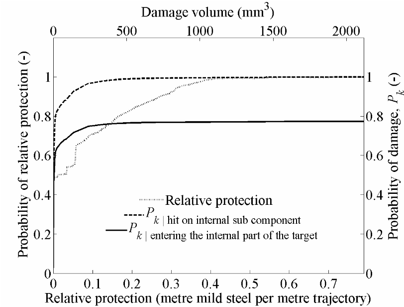
The results are summarized by a probability of hitting internal subcomponents, a cumulative kill probability given hit on an internal component and tables with relative protection and cumulative kill probability given hit as a function of damage volume. Figure 1 gives an example of plotted data from these tables.
The resulting data is to be used in a one-component description of the target, with internal protection and penetration kill criteria given as results from the simulations.
Simulation input requirements
There are a few prerequisites in order to evaluate the kill criteria by simulations. Obviously a component has to be described as a target for the V/L-tool. In the case of AVAL’s kill criteria evaluation simulation type there is also a second input data file required, defining the simulation conditions.
Target description
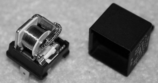
A target description of the component is needed in order to run the kill criteria generation simulation. This describes the geometry and material for the component with all its subcomponents. It also defines a fault tree that includes the so called vital subcomponents in order to find the target’s functionality status based upon the status of each included subcomponent. The relay target description is shown in Figure 2 and the original component in Figure 3.
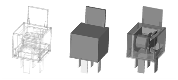
Each vital subcomponent in the relay is given an estimated kill criterion, which relates the probability of functionality loss to the damage crater volume in the subcomponent. A leading idea in this work is that each subcomponent should be very sensitive to damage, and thus its kill criterion should be relatively easily estimated.
A total of 170 vital subcomponents (internal subcomponents and external electrical connections) and 31 structural (for the plastic cover) are defined. The fault tree for this target defines only one top event, called ‘Relay killed’. This top event will occur if at least one of the sub-events occurs. There are 11 sub-events defined and each will occur if at least one of the included subcomponents is killed.
Set-up data file
All subcomponents defining the outer boundaries of the component target have to be listed in order for AVAL to be able to evaluate the internal protection to be used in the simplified component description. This is done in an input data file for the simulations. The fault tree top events to be evaluated, penetrator diameters, evaluation time and penetrator type are also specified in the same file. Even though no penetration calculations are performed, the penetrator type is needed in order to find the correct penetration resistance and crater diameter for each material in the component target. An identification of the reference material mild steel is also given in order for AVAL to be able to present an internal protection for a one component description of the target with only one internal material.
Simulation methodology limitations
There are a number of probable shortcomings with the AVAL implementation of this method to define kill criteria, which are likely to affect the results.
Penetration damage only
The simulations only consider penetration damage, defined by crater volume in subcomponent or projectile penetration capability at impact, according to AVAL´s rather simplified penetration model. In a small component, like the relay, there will also be damage due to bending and dislocation of subcomponents. These kinds of damage are neglected in the simulations. It is also possible that an electrically conducting projectile causes a shortcut between some electrical subcomponents without physically damaging them. Neither this phenomena is considered in the simulations. This will probably underestimate the kill probability.
Ray-tracing
The simulations will not be able to indicate a hit on a subcomponent when the trajectory line does not intersect the subcomponent, since the hit points on the subcomponents are found by ray-tracing with an infinitesimal ray. When the ray is closer than the radius of the projectile it should hit. There might even be occasions when the ray passes between several closely located subcomponents that all should have been hit if the ray-tracing was replaced by a cylindrical volume-tracing. This will probably underestimate the kill probability significantly for small targets, such as the relay.
Geometrical definition of subcomponents
AVAL is currently unable to handle concave geometries, which mean that all non-convex subcomponents must be defined by combining several smaller convex parts. All these small parts are evaluated individually as separate subcomponents, with their own kill criteria if they are hit. This might in some cases overestimate and in others underestimate the kill probabilities.
Simulations
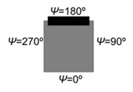
Simulations have been performed with AVAL 6.8.03, covering impacts perpendicular to the same four faces that were impacted in the experimental study [11], see Figure 4. The penetrators were chosen to be of the type ‘fragment’ with diameters ranging from 1 mm to 15 mm, in 1 mm intervals. Impact velocity, mass, and corresponding penetration performance was not defined since it is not needed for the kill criteria simulations.
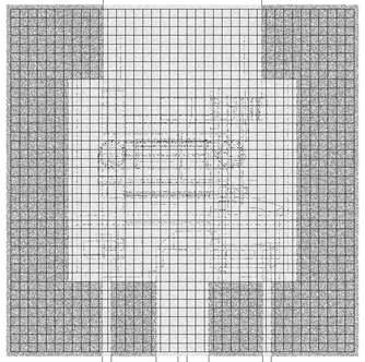
The hit pattern grids were defined by 1 mm × 1 mm cells and 500 parallel rays were randomly placed around each node, see Figure 5. The grid does not cover all of the upper mounting plastic or the complete cable connectors, since these areas are out of the scope of this study.
Simulation results
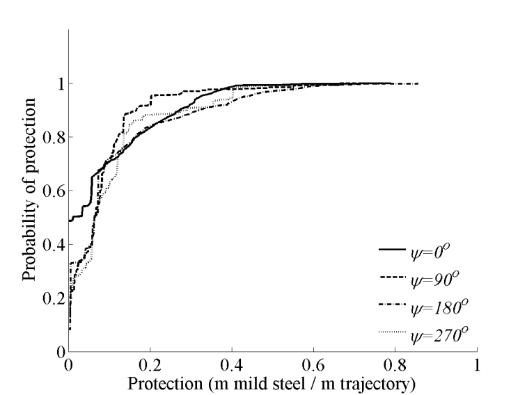
Figures 6 to 8 presents the simulation results, for each one of the four impact directions. In order to use this information for a one-component description of the relay the kill probability must be connected to the internal protection, otherwise it will not be valid. According to Figure 6 roughly one third of the rays passed the relay without hitting any internal subcomponent and thus did not meet any penetration resistance. The highest relative protection corresponds to about 0.9 m mild steel per metre trajectory through the component—that is, a local fill degree of about 90%.
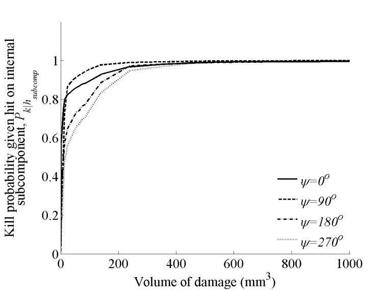
The cumulative kill probabilities are presented both directly from the result files, Figure 7, and corrected with the hit probability of internal subcomponents, Figure 8. The probabilities of hitting an internal subcomponent are given in Table 1. It is clear that the hit probabilities are in reasonably good agreement for opposite impact directions.
The results in Table 1 can also be used to define the so called sensitive area [12] or vulnerable area [4] of the component.
Figure 7 clearly demonstrates that the relay is easily killed if the internal subcomponents are hit. It should in this case be noted that the damage volume cross sectional area is defined by the penetrator diameter, which in many cases are greater than the impacted subcomponent of this relay. For damage volumes over 300 mm3, the cumulative kill probability is close to 1.00. This is to be compared with the relay’s total internal volume of roughly 243≈14000 mm3.
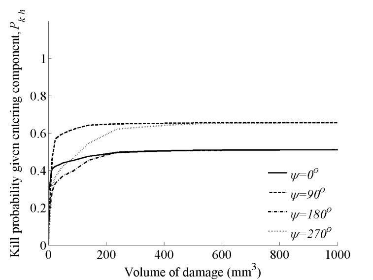
The cumulative kill probabilities given that the rays entered the interesting part of the relay are found by multiplying the kill probabilities according to Figure 7 with the hit probabilities according to Table 1. These probabilities are shown in Figure 8, where two distinct groups can be seen. The kill probabilities are quite similar for front / rear attacks (Ψ=0º and Ψ=180º) and for left / right attacks (Ψ=90º and Ψ=270º). This is due to the probability of hitting any internal subcomponents.
The initial difference in kill probabilities for Ψ=90º and Ψ=270º are probably due to the construction of the relay. When firing from the left side (Ψ=270º), a rather robust (and in the target description non vital) subcomponent is hit first, thus requiring a greater damage volume before the relay is killed.
One type of available component penetration kill criterion for AVAL gives the cumulative kill probabilities for a number of damage volumes, independent of impact direction. Such a table can be produced based upon an average of the curves in Figure 8 and is presented in Table 2. AVAL utilises linear interpolation between given values and the nearest value when out of range (in this case the kill probability is constant for damage or crater volume over 400 mm3).
| Impact angle | 0º | 90º | 180º | 270º |
|---|---|---|---|---|
| Impact face | front | right | rear | left |
| Hit probability | 0.51301 | 0.65662 | 0.51312 | 0.65645 |
| Damage volume (mm3) | 0 | 30 | 200 | 400 |
|---|---|---|---|---|
| Kill probability, Pk (-) | 0.00 | 0.42 | 0.56 | 0.58 |
| Proj. | Partial penetration (m/s) | Complete penetration (m/s) | Mean (m/s) | V50 (m/s) | ||
|---|---|---|---|---|---|---|
| 4 mm | 66.68 | 71.45 | 68.16 | 68.79 | 68.77 | 70 |
| 6 mm | 36.43 | 37.61 | 37.44 | 38.68 | 37.54 | 40 |
| 8 mm | 28.35 | 29.02 | 31.76 | 28.93 | 29.51 | 30 |
| Projectile, | Number of surviving relays (of 3) | |||||||
|---|---|---|---|---|---|---|---|---|
| measured diameter and mass | Impact angle Ψ | Normalized impact velocity (v/V50) | ||||||
| 1 | 2 | 3 | 4 | 5 | 6 | 7 | ||
| 4 mm | 0º | 3 | 1 | 0 | 0 | 0 | 0 | 0 |
| 3.95 mm | 90º | 3 | 2 | 0 | 0 | 0 | 0 | 0 |
| 0.25 g | 180º | 3 | 2 | 3 | 3 | 3 | 0 | 0 |
| 270º | 3 | 3 | 2 | 3 | 0 | 0 | 0 | |
| 6 mm | 0º | 3 | 0 | 0 | 0 | 0 | 0 | 0 |
| 6.35 mm | 90º | 3 | 0 | 0 | 0 | 0 | 0 | 0 |
| 1.04 g | 180º | 3 | 2 | 3 | 0 | 0 | 0 | 0 |
| 270º | 2 | 3 | 2 | 0 | 0 | 0 | 0 | |
| 8 mm | 0º | 3 | 0 | 0 | 0 | 0 | 0 | 0 |
| 8.00 mm | 90º | 3 | 0 | 0 | 0 | 0 | 0 | 0 |
| 2.08 g | 180º | 3 | 3 | 2 | 0 | 1 | 0 | 0 |
| 270º | 3 | 2 | 0 | 0 | 0 | 0 | 0 |
Comparison with experimental results
Experimental results from impacts of spherical projectiles on all four faces have previously been published [11]. These results are given as ballistic limit velocities in Table 3 and number of killed relays (of three tests in each case) in Table 4. The grey cells in Table 4 are estimated to be no surviving relays since all tested were killed at a lower impact velocity.
There are some encouraging resemblances between Table 4 and Figure 8. According to Figure 8, it is hardest to kill the relay by firing from the rear side (Ψ=180º) and this is also evident in Table 4. Also for the impact direction with the highest kill probability according to Figure 8 (Ψ=90º) there is a good but not as evident correspondence with Table 4. Further detailed comparisons are not really practical since the simulation results give the kill probability as function of damage volume, which is not directly available in the experimental study. It is however obvious that the overall kill probabilities in Figure 8 are too low. According to Table 4 the relay was killed for every impact direction and projectile diameter, with a high enough impact velocity.
Estimates of maximum possible theoretical damage volume can be found by multiplying the cross sectional areas of the projectiles with a trajectory length of 24 mm. This gives for the 4 mm projectile 294 mm3, for the 6 mm projectile 760 mm3 and for the 8 mm projectile 1206 mm3. In reality the maximum damage volumes should be reduced since a large part of the relay interior is void, as illustrated by the internal relative protection in Figure 6, and many subcomponents are smaller than the projectile’s cross sectional areas.
Discussion
So far the simulation and experimental results are still kept separated based upon the impacted side. Before a component kill criteria is defined, which is independent of the impact direction, more impact directions should be evaluated and all these results have to be averaged in some way similar to the estimation in Table 2.
There are tendencies of similarities between the simulation and experimental results, but it is also obvious that the simulation results gives significantly lower kill probabilities. This might in part be caused by unfortunate estimations of kill criteria for the subcomponents in the relay target description. A more plausible reason is, however, due to the target size in relation to the projectile sizes.
Since the simulations are based upon ray tracing with infinitesimal rays though the target the probability of hitting internal subcomponents is only in the range 0.5–0.7, depending on the attack direction. In the experimental study physical projectiles with the cross sectional areas 12, 32 and 50 mm2 was fired against the centre of each side of the relay. This means that a projectile covers 2%, 6% or even 9% of the impacted face which is a significant part and far away from the infinitesimal ray. The ray tracing method thus is not really applicable for a target of this small size in relation to the projectile sizes. With another way of finding the component intersection with the trajectory—for example, with a cylinder intersecting the target, a higher number of subcomponents would be hit.
Furthermore, the hit points are evenly distributed in the simulations whilst the experimental hit points are focused around the centre of each impacted side. Due to the design of the relay it ought to be easiest to kill when impacted closely to the side centre, and at the edges it could in some cases be possible for a small projectile to pass the component without hitting any internal subcomponent.
In V/L-tools that are Monte Carlo based a large number of simulations are required to get the results. Therefore each simulation cycle must be fast and the models are designed with this in mind. There are thus a number of probable damage mechanisms that normally are excluded from the simulation codes. In the case of this relay, the experiments does not give a penetration damage—that is, a crater, as would have been the case if a projectile impacted a massive plate of a uniform material. Instead there is bending and dislocation of subcomponents; there might be electrical short cuts and so on. None of these mechanisms are covered by the AVAL code used for the simulations.
It is also hard to compare the experimental impact results with the crater volumes given from the simulations. In one case there are masses, diameters and impact velocities and impact positions close to the centre of each face, and in the other there are only crater volumes given impact on the faces. The results from the AVAL kill criteria simulations are formatted as one of the input data format for penetration kill criteria and internal protection. In order to compare the kill criteria with experimental results they should preferably be expressed in physical properties, such as impact momentum or energy. That would on the other hand neglect the performance of the penetrator—for example, it is in some cases possible to increase the penetration performance and hence the crater volume by heat treating the projectile, whilst keeping mass and impact velocity.
At the moment it seems to be best to use the internal protection found by the kill criteria simulations when defining a simple component description. The internal protection will vary between successive Monte Carlo cycles in contrast to setting an average density for the internal material. To define the kill criterion, which is in focus here, it is probably better to run regular grid simulations using penetrators and impact directions corresponding to the ones used in the experiments. This will however not resolve the main problem of ray tracing for a component of this small size.
With a better alternative to regular ray tracing and simulation impact conditions defined in such a way that they can be compared with the experimental study this is still a plausible way of defining the kill criterion. The concept of running simulations on a high fidelity description of a component with a V/L-tool in order to define kill criterion and other data needed for a simple description is thus still worth pursuing, despite the drawbacks presented here.
Conclusions
Since experimental studies to find penetration kill criteria will become very expensive an additional method is needed. Simulations with V/L-tools where the normal platform level target—for example, a vehicle, ship or aircraft, is replaced by a highly detailed description of the component can be one such method.
This study found similarities between the experimental and simulation results. The overall kill probabilities are however significantly lower in the simulations. This is probably due to the ray tracing technique used in combination with the size of the target in relation to the diameter of the projectiles fired at it. If the ray tracing could be replaced by some kind of “cylinder” tracing or evaluated in bundle of rays instead of single rays the kill probability is believed to increase and close in on the experimental results.
References
[1] P. Tanenbaum, “Vulnerability / Lethality Methodology”, in course documentation of Vulnerability / Lethality, May 21–24 1990, Balitmore MD, Computational Mechanics Associates.
[2] L. Xiandong, Z. Yunfa, and W. Huizhi, “A Research on the Damage Criteria of Target Components in Vulnerability Assessments”, Proceedings of 17th International Symposium on Ballistics, Midrand, South Africa, 23–27 March 1998.
[3] R. Ball, The Fundamentals of Aircraft Combat Survivability Analysis and Design, AIAA Education Series, 2003.
[4] M. Driels, Weaponeering—Conventional Weapon System Effectiveness, AIAA Education Series, 2004.
[5] M. Hartmann, Component Kill Criteria—A Literature Review, Swedish Defence Research Agency, FOI-R--2829--SE, August 2009.
[6] R. Putzar, F. Schaefer, and M. Lambert, “Vulnerability of Spacecraft Harnesses to Hypervelocity Impacts”, International Journal of Impact Engineering, Vol. 35, 2008, pp. 1728–1734.
[7] F. Schäfer, S. Ryan, M. Lambert, and R. Putzar, “Ballistic Limit Equation for Equipment Placed Behind Satellite Structure Walls”, International Journal of Impact Engineering, Vol. 35, 2008, pp. 1784–1791.
[8] M. Hartmann, Methodology for Decisions for Kill Criterion of Components—A First Step, Swedish Defence Research Agency, FOI-R--1755--SE, November 2005 (in Swedish).
[9] I. Eriksson and M. Hartmann, “A Method for Assessing Kill Criteria for Critical Components in Survivability Codes”, Proceedings of 3rd European Survivability Workshop, 16–19 May 2006, ENSICA, Toulouse, France.
[10] H. Gustafsson and P. Karlsson, “Produce Criteria’s for Vital Components by Simulations”, Proceedings of 3rd European Survivability Workshop, 16–19 May 2006, ENSICA, Toulouse, France.
[11] M. Hartmann and P. Magnusson, “Component Impact Kill Criteria—An Experimental Study”, Journal of Battlefield Technology, Vol. 13, No. 2, July 2010, pp. 13–18.
[12] R. Helfman, J. Saccenti, R. Kinsler, and J. Suckling, An Expert System for Predicting Component Kill Probabilities, Memorandum Report BRL-MR-3473, US Army Ballistic Research Laboratory, Aberdeen Proving Ground, October 1985.