
Volume 15, Number 2, July 2012
Visco-Elastic Polyurethane Foam As An Injury Mitigation Device In Military Aircraft Seating
- * Air Vehicles Division (AVD), Defence Science and Technology Organisation (DSTO), Melbourne, Australia.
Abstract
Energy-absorbing seats have become an important component of aircraft design, providing additional safety for occupants during crash impacts. Although the design of seat systems has not traditionally considered the cushion as an energy absorption device, some new aircraft incorporate cushions as an energy-absorption mechanism, using Visco-elastic Polyurethane (VEPU) foams. The literature indicates that VEPU cushions could potentially result in a significant reduction in impact force to the seat occupant, when compared to more conventional cushions. Vertical impact tests have been conducted on a drop test machine to determine the impact profile of cushions and their potential to reduce force transmitted to a seat occupant during a 2.0–8.2 m/s crash. Traditional basic seat foams and commercially available VEPU foams were used. The VEPU foams significantly reduced the impact loading as expected. The optimum density and stiffness of VEPU cushions depended on the level of maximum impact loading. While more work is required, a properly selected VEPU cushion of the same dimensions as current cushions used in existing aircraft seating is likely to provide significant crashworthiness improvement and also reduce occupant fatigue.
Introduction
Aircraft crash impact
Impact and load transfer
During a crash scenario, an aircraft will experience large deceleration forces in vertical, forward and lateral directions. In the ideal case, the aircraft velocity must gradually decrease to zero to protect occupants from sudden large deceleration forces. Crash survivability is focused on a systems design approach, where the impact energy is absorbed through three primary mechanisms: stroking of the landing gear, collapse of the sub-floor structure, and stroking of the seats and restraint system [1]. An acceleration-time graph of these systems during a crash is shown in Figure 1. A good design exploits the ability of the structure to dissipate the kinetic energy of the aircraft during crash landing.
![Acceleration of various aircraft crash systems showing the different crash systems acting to absorb force across the crash duration [1].](/journals/journal-of-battlefield-technology/volume-15/issue-02/assets/15-2-2-saunders/figures/figure01.png)
Approximately 85% of aircraft accidents are considered potentially survivable [2]. A survivable accident is one in which the forces transmitted to the occupant body do not exceed the limits of human tolerance due to abrupt accelerations. It is also imperative that the structure in the immediate environment of the occupant remains substantially intact, to the extent that a liveable volume is provided for the occupants throughout the crash sequence [1].
The seat system
The energy-absorbing seat is now an important component of aircraft design. In the case of a crash, the loads experienced by the aircraft structure may exceed those identified by the limits of human tolerance, so load attenuation needs to be achieved through improving the capabilities of the primary energy absorbing mechanisms, such as the seats.
In order to maximise the efficiency of the seating system, the load limiting function is designed such that it allows the seat and occupant to move (stroke), at loads just under the humanly tolerable limit, over the maximum distance available in the aircraft [3]. Improved energy absorbing seats are desired for fixed and rotary-wing aircraft to enhance load attenuation during crash events.
The seat cushion
MIL-S-58095A is the specification that details the requirements for military seat system crash resistance. It sets out in Section 3.11.4 that the “seat cushions shall be designed for comfort and durability and not as a device to absorb crash energy”. As such, the design of seat systems has not traditionally considered the cushion of an energy absorption device. However, new aircraft have started incorporating the cushion as an absorber of energy. Use of VEPU cushions to reduce impact force to the occupant has been reported [4].
The use of energy absorbing seat cushions needs to take into account both safety and comfort which brings about two specific considerations. Firstly, the downwards displacement of the torso into the maximum crush of the cushion must not produce excessive slack in the restraint harness. Secondly, the cushion must also be thick enough to provide comfort. Any additional cushion thickness can only be justified if it absorbs the energy more efficiently or effectively compared with the situation were the space is utilised by the stroke mechanism of a seat system [5].
Visco-elastic polyurethane (vepu) foam
Polyurethane foam seat cushions
The unique mechanical properties of polyurethane (PU) foams make them attractive for investigation in reducing impact force on vehicle seat occupants. PU foams are reliable, practical and effective as an energy absorption (EA) concept [6]. In addition they are cheap, light, and do not carry the numerous design issues associated with many other energy-absorbing concepts.
Wang and Roy [6] investigated the use of a single PU foam seat cushion for protection against landmine blasts in military vehicles. Extensive experimental work was carried out to validate predictions made by computer modelling using full-scale drop tests with a Hybrid III anthropomorphic test device pelvis and upper body mass. Force data were collected with a load cell incorporated into the test device. The authors found PU foams to be effective as an EA device.
The stress-strain curve shown in Figure 2 applies to all foams under a compression load. The curve is split into three regions [7]:
![The typical shape of the compressive stress-strain curve for foam, showing the behaviour of foam under compressive load [11].](/journals/journal-of-battlefield-technology/volume-15/issue-02/assets/15-2-2-saunders/figures/figure02.jpg)
- Linear “Hookian” behaviour—where the linear elastic behaviour is controlled by cell wall bending.
- Collapse plateau—where the cells collapse through cell wall buckling, yielding or crushing.
- Densification—where the cell walls crush together.
The area under the stress-strain curve accounts for the energy absorbed by the foam. A large portion of the energy from an impact will be absorbed in the plateau region of the stress-strain curve where cells deform by elastic buckling, plastic yielding or brittle crushing [7]. Hence, for a given impact, the peak force on the occupant can be reduced by optimising the kinetic energy absorbed in the plateau region.
Density is a key property of foams. Vladimir [8] considered the importance of density in relation to the energy absorption of foam. Figure 3 shows the energy diagram of foams of different density. When the foam density is too low for the application, the densification zone is reached (that is, bottom out), and a higher stress is observed before the energy has been dissipated. When the density is too high, the compressive strain of the material is only partially utilised, and a high stress is observed before enough energy has been absorbed. In both cases the seat occupant will experience a high impact force.
Visco-elastic polyurethane foam seat cushions
The Visco-Elastic Polyurethane (VEPU) foam, also commonly referred to as memory, temper or “slow-release” foam, is a material that was developed by scientists at NASA in the mid 1960’s [9,10]. The material was invented to reduce the acceleration force experienced on the body of an astronaut during exit and re-entry back into the Earth’s atmosphere. VEPU foam is a common product developed by industries worldwide. VEPU foam can be produced with a range of mechanical properties, making it a popular material within the medical, bedding, household, sporting, and commercial aircraft industries.
VEPU foam is composed of an “open cell” structure made from PU and additional chemicals. These additives affect both the material viscosity and density. Under compression load the open cells “collapse” and spread the air pressure within adjoining cells.
VEPU foam seat cushions have been shown to be highly effective as an EA device [4,11–12]. The internal damping properties of VEPU foams allow impact energy to be dissipated very effectively. In addition, the foam distributes static load evenly over a surface. This feature may reduce peak force on a body, during blast or crash scenarios. Currently, these foams are marketed internationally in the recreational aircraft industry as effective EA materials. However, information with regard to the specific mechanical properties of these products remains limited.
Resilience, or the surface elasticity of the foam, is a widely discussed EA property of VEPU foam [13]. The resilience of foam is measured by dropping a steel ball on a foam sample and measuring the rebound height. Ball rebound of less than 20% of the predetermined drop height (compared to 50–60% with other varieties of flexible PU foam) supports the description of VEPU foam as a low-resilience foam [14]. Some VEPU foam manufacturers for products such as Sunmate, and Confor claim to absorb up to 90% and 97% of impact, respectively [15–16].
Visco-elasticity (VE) is the property of a material that exhibits both viscous and elastic characteristics when undergoing deformation. A seat cushion made of an elastic material subject to high impacts, can cause a significant peak force exerted on the occupant as the cushion springs back after deformation. VE materials dissipate energy when a load is applied and then is removed in the form of a hysteresis loop. The result is that the stress-strain curve in recovery does not follow the same path as the loading [17]. There is consequently a loss of energy from the foam material, which is converted into heat energy. The ability of VE materials to dissipate energy effectively makes it a preferable material for absorbing high impact loads.
As shown in Figure 4, compared with standard foams, VE foams show a smaller increase in force at higher deformations. The large hysteresis loop in the VE foam curve reflected a larger amount of energy lost as heat in the loading and unloading cycle, as a result of the slow compression and recovery of the material. Whittle [17] investigated the use of VEPU foams in insoles, and concluded that the viscous properties of VEPU foam depends on the rate at which it is deformed. In selecting materials for high impact application, it is important to examine the material properties at an appropriate loading.
![Energy diagram of foams of different density. The shaded area under each curve corresponds to the same amount of energy absorbed [8].](/journals/journal-of-battlefield-technology/volume-15/issue-02/assets/15-2-2-saunders/figures/figure03.gif)
![Comparison between visco-elastic foam and standard foam undergoing compression loading and unloading [17].](/journals/journal-of-battlefield-technology/volume-15/issue-02/assets/15-2-2-saunders/figures/figure04.jpg)
Segal [11,12] conducted full-scale drop testing with a Hybrid III anthropomorphic test device to study the effect of VEPU cushion thickness on occupant lumber load. The impact velocity was at 9.4m/s. Testing on a 5th percentile female, 50th and 95th percentile male test device showed a clear and significant reduction in impact force with cushion thickness. A maximum foam thickness of 4 inches was found to reduce lumber load by approximately 40% for all test dummies, compared to a bare seat.
Purpose of this study
The purpose of this study was, by using vertical drop impact tests, to determine the impact profile of several VEPU foam cushions (with different densities/stiffness) and their potential, in an optimum manner, to reduce the level of force transmitted to a seat occupant during an aircraft crash or other impact.
Experimental method
Experimental set up
The experiment was conducted on the vertical drop test rig at the Defence Science and Technology Organisation (DSTO) in Fishermans Bend, Victoria. This test rig consists of a rigid test bed, guiding rods, drop mass and magnesium dampening block (Figure 5). The testing medium is placed directly on top of the test bed. The mass is raised to the appropriate height by a winch then released by a “bomb” catch. The mass is then guided down by the guiding rods at approximately 9.8 m/s2 A magnetic trigger is set off 0.2m from the ground by the mass at which point an accelerometer attached to the top of the mass records the acceleration of the mass, and a laser displacement device records the mass’ displacement. The testing medium is then impacted by the drop mass. During a real crash scenario a seat occupant would already be strapped into the seat, with the cushion potentially already partially compressed prior to impact. The effects of free fall would further release the seat occupant’s compression of the foam prior to impact.
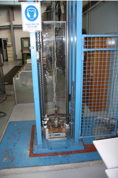
This test rig enables testing to be performed at up to 4.1m drop height (8.2 m/s impact velocity).
A surrogate occupant such as a Hybrid III anthropomorphic test device would not fit into the test rig in use, and thus a drop mass was utilised. It is considered that a Hybrid III anthropomorphic test device’s mass without legs is approximately 65 kg, and its contact with a seat is around 0.0986 m2 (31.4 cm×31.4 cm) which was calculated to create a load per unit cushion area of 6.47 kN/m2. Given the test rig’s space limitations a cushion size of 25.4 cm×25.4 cm was selected, which therefore required a mass of 41.2 kg to create the same load per unit cushion area.
Foam selection
Six types of foam samples were sourced from commercial suppliers and two existing aircraft seats were also used (refer to Tables 1 and 2). Foams were tested at one inch (2.54 cm) and three inch (7.62 cm) thicknesses.
| Foam | Density (kg/m3) | Supplier |
|---|---|---|
| Sunmate X-Firm | 94.815 | Dynamic Systems Inc |
| Sunmate XX-Firm | 94.815 | Dynamic Systems Inc |
| Confor Laminate | 85.333 | US Aircraft Spruce & Specialty Co. |
| Confor Tri Laminate | Variable | US Aircraft Spruce & Specialty Co. |
| Dynafoam X/XX-Firm Laminate | 82.963 | Airplane Flight Equipment |
| Baseline Yellow Foam | 28.444 | Clark Rubber |
| Foam | Density (kg/m3) | Comments |
|---|---|---|
| Sample A | Unknown | Non-VEPU foam, appears similar to Yellow basic foam, ≈ 1 in thick |
| Sample C | Unknown | VEPU foam, appears similar to Confor, ≈ 3 in thick |
Testing
Vertical impact velocity (drop height)
The crash worthiness standards (MIL-S-58095 and MIL-S-85510) require a military helicopter to be so designed that a crash of the helicopter with up to 15.2 m/s vertical impact velocity should be a survivable crash. As shown in Figure 1, during a crash event, the landing gear stroke will give the helicopter system initial deceleration. Therefore, in a seat drop test a lower vertical impact velocity is considered (typically 8m/s, refer to MIL-S-58095 and MIL-S-85510). After the fuselage contacts the ground, seat stroke begins when the acceleration is beyond a preset value to limit the peak acceleration (load) to the occupant. In a survivable crash, the seat and occupant come to rest without giving excessive inertial force to the occupant.
The drop impact velocities used in this study were based on the above considerations. Initial tests were conducted using a high impact velocity of 8.2 m/s (resultant from a drop height of 4.1m) to investigate the effect of the seat cushion in a crash event where either the impact velocity is significantly higher than that defined for the survivable crash or the seat stoke mechanism is assumed to be not functioning properly. In these cases, the occupant will experience a period of large acceleration with the seat cushion being the only energy absorbing mechanism. Further experiments were conducted at lower impact velocities of 2, 2.4 and 2.8 m/s (0.25, 0.375 and 0.5m drop heights). Since the seat cushion only makes up part of the seat system, as such these lower impact velocities were to explore the possibility that the improved seat cushion may further reduce the impact load to the occupant in a survivable crash, or increase to a certain extent the allowable impact velocity of a survivable crash assuming it only takes part of the deceleration force.
Assumptions, simplifications and limitations
The testing is subject to the following assumptions, simplifications and limitations:
- The foam does not deteriorate over the number of trials conducted.
- The impact only occurs in the vertical direction and does not take into account any forces the occupant may be subjected to in the longitudinal and lateral directions.
- The occupant is represented using a rigid mass. The weight is not acting on the cushion during the vertical free fall and only begins to act at the moment the impact occurs.
Reliability of test results
As a result of installation of a new accelerometer before the low velocity drop tests were conducted, the instrumentation system was recalibrated. The reliability of the acceleration measurement of the drop test was verified by comparing it’s double integration with the displacement measured from the laser displacement device. Results were also repeated three times (except for sample C, Sunmate X and Sunmate XX one inch foams, due to limited testing time) and the results were shown to be repeatable. The error was generally within ± 2g (~5%) peak acceleration, and ± 1.5 ms (~5%) impact duration. The drop height error was ± 0.005m.
Results processing
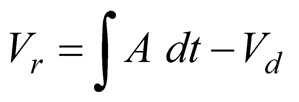
In addition to direct measurement of the acceleration of the drop mass, the re-bounce velocity of the mass, Vr, and impact energy absorbed during impact, Es, are obtained using the following formulae:
where
A = the measured acceleration
t = time
Vd = drop impact velocity
m = drop mass (41.2 kg)
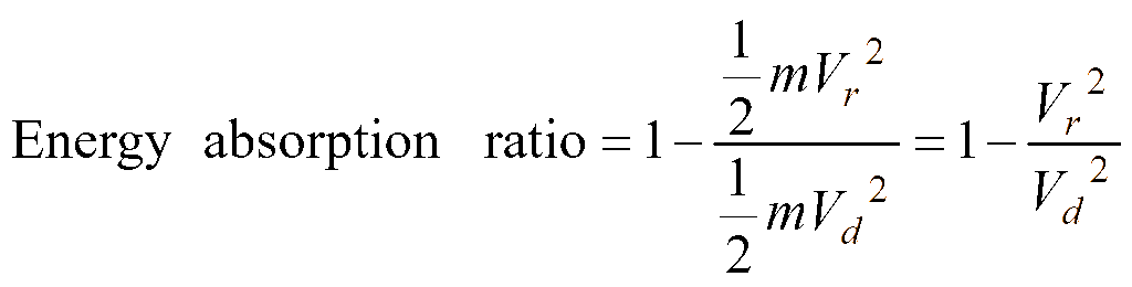
A high Es value is an indication of a high-energy-absorbing cushion. The energy absorption can also be expressed in terms of its percentage to the total kinetic energy prior to the impact:
Results and discussion
High impact drop tests—8.2 m/s impact velocity with 3” foams
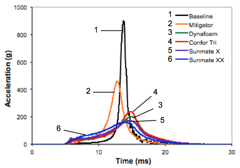
As described above, the high velocity vertical impact test was performed with a drop height of 4.1m corresponding to an impact velocity of approximately 8.2 m/s. Testing was conducted on three inch thick VEPU foam specimens. The results are summarised in Figure 6 and Table 3.
| Foam | Peak Acceleration (g) | Peak Acceleration compared to Baseline (%) | Energy absorbed (%) |
|---|---|---|---|
| Baseline—Yellow | 898.8 | – | 68.3 |
| Mitigator | 458.7 | 51.1 | 54.0 |
| Confor Tri | 202.0 | 22.5 | 79.1 |
| Dynafoam X/XX | 240.0 | 26.7 | 69.8 |
| Sunmate X | 175.6 | 19.5 | 80.8 |
| Sunmate XX | 160.1 | 17.8 | 86.1 |
| Foam | Peak Acceleration (g) | Peak Acceleration compared to Baseline (%) | Energy absorbed (%) |
|---|---|---|---|
| Baseline—Yellow | 64.9 | - | 50.1 |
| Sample C | 15.9 | 24.5 | 97.8 |
| Confor Tri | 16.7 | 25.7 | 81.4 |
| Dynafoam X/XX | 24.3 | 37.4 | 85.4 |
| Sunmate X | 34.5 | 53.2 | 88.4 |
| Sunmate XX | 59.6 | 91.8 | 87.4 |
These results showed that the VEPU foams reduced the peak acceleration on impact significantly compared to the baseline foam. In the case of Sunmate XX Firm foam, the reduction of the impact peak load was as high as 85%. While none of these results reduced the impact to an acceptable level to mitigate injury of less than 30g [18], it should be noted that the entire energy absorbing system (including the stroke of the seat frame system), is designed to reduce the impact to less than 30g. As such these results indicate that VEPU foam may contribute significant reductions in the peak forces transmitted to a seat occupant, in conjunction with the remaining seat system.
These results also indicate that the higher density foams were able to decrease the peak acceleration more than the lower density foams. Hence, if the foam is required to reduce high peak accelerations, then the results indicate that a higher density foam should be used.
Reduced velocity impact drop tests
As discussed earlier, it is unlikely that the cushion alone would be expected to absorb the full energy of the entire seat system. It is expected that the seat structure would absorb a significant amount of the total energy. Thus testing was also conducted at impact velocities of 2.0, 2.4, and 2.8 m/s to determine the impact profile of a reduced velocity impact.
Impact velocity of 2.8 m/s with 3” thick foam
As shown in Figure 7 and Table 4, at an impact velocity of 2.8 m/s (0.5m drop height) the three inch VEPU foams all showed a reduction in the peak acceleration of the drop mass. All the VEPU foams except the Sunmate XX reduced the peak acceleration significantly compared to the baseline foam.
Impact velocity of 2.8 m/s with 1” thick foam
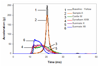
The results with an impact velocity 2.8 m/s (0.5m drop height) with one inch foam are given in Figure 8 and Table 5. The one inch VEPU foams are less effective in reducing the peak acceleration compared with the three inch VEPU.
However, compared with the baseline foam, the one-inch VEPU foams also significantly reduced the peak acceleration of the drop mass. The lower density and lower stiffness foams (Confor and Dynafoam) reduced the peak acceleration by over 80%, which is more significant than the three inch foams when compared with the baseline foam.
The data in Table 5 also show that the VEPU foams significantly increased energy absorption during the impact, in comparison with the performance of the baseline foam.
Impact velocity of 2.4 m/s with 3” thick foam
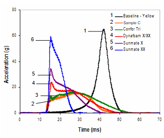
As shown in Figure 9 and Table 6, at an impact velocity of 2.4 m/s (0.375m drop height) the three inch thick VEPU foams, except for the Summate XX, reduced the peak acceleration.
| Foam | Peak Acceleration (g) | Peak Acceleration compared to Baseline (%) | Energy absorbed (%) |
|---|---|---|---|
| Baseline - Yellow | 255.2 | – | 24.4 |
| Sample A (non-VEPU) | 201.6 | 79.0 | 30.3 |
| Confor | 48.0 | 18.8 | 75.7 |
| Dynafoam X/XX | 46.6 | 18.3 | 73.7 |
| Sunmate X | 48.0 | 18.8 | 85.1 |
| Sunmate XX | 77.3 | 30.3 | 87.0 |
| Foam | Peak Acceleration (g) | Peak Acceleration compared to Baseline (%) | Energy absorbed (%) |
|---|---|---|---|
| Baseline—Yellow | 39.6 | - | 60.2 |
| Sample C | 12.9 | 32.6 | 96.8 |
| Confor Tri | 14.9 | 37.6 | 80.2 |
| Dynafoam X/XX | 23.1 | 58.3 | 86.0 |
| Sunmate X | 33.0 | 83.3 | 87.8 |
| Sunmate XX | 63.4 | 160.1 | 83.7 |
Impact velocity of 2.4 m/s with 1” thick foam
These are the first impact conditions where the VEPU foam, Sunmate XX, performed worse than the baseline foams. This is likely due to the high stiffness (density) of the foam, and indicates that it is critical to consider the density and stiffness of the foam based on the expected impact conditions (refer to Figure 4 and the associated discussion).
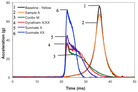
As shown in Figure 10 and Table 7, at impact velocity 2.4 m/s (0.375m drop height) but with one inch thick foams, all the VEPU foams had significant reductions in the peak acceleration and an increase in energy absorption, including Sunmate XX, compared to the baseline foam. The Dynafoam and Confor M foam again perform most efficiently, decreasing the peak acceleration by over 75%, to just above 30g.
| Foam | Peak Acceleration (g) | Peak Acceleration compared to Baseline (%) | Energy absorbed (%) |
|---|---|---|---|
| Baseline—Yellow | 159.1 | – | 17.2 |
| Sample A (non-VEPU) | 126.3 | 79.4 | 28.2 |
| Confor M | 38.6 | 24.3 | 77.2 |
| Dynafoam X/XX | 35.9 | 22.6 | 77.2 |
| Sunmate X | 43.3 | 27.2 | 83.7 |
| Sunmate XX | 79.2 | 49.8 | 86.5 |
| Foam | Peak Acceleration (g) | Peak Acceleration compared to Baseline (%) | Energy absorbed (%) |
|---|---|---|---|
| Baseline—Yellow | 20.4 | – | 78.0 |
| Sample C | 11.4 | 55.9 | 93.5 |
| Confor Tri | 11.2 | 54.9 | 86.7 |
| Dynafoam X/XX | 20.3 | 99.5 | 92.3 |
| Sunmate X | 29.6 | 145.1 | 94.4 |
| Sunmate XX | 57.3 | 280.9 | 87.2 |
| Foam | Peak Acceleration (g) | Peak Acceleration compared to Baseline (%) | Energy absorbed (%) |
|---|---|---|---|
| Baseline—Yellow | 76.3 | – | 31.4 |
| Sample A (non-VEPU) | 67.8 | 88.9 | 39.8 |
| Confor M | 39.8 | 52.2 | 82.0 |
| Dynafoam X/XX | 36.4 | 47.7 | 79.4 |
| Sunmate X | 45.2 | 59.2 | 92.4 |
| Sunmate XX | 73.3 | 96.1 | 90.4 |
Impact velocity of 2.0 m/s with 3” thick foam
Referring to Figure 11 and Table 8, at an impact velocity of 2.0 m/s (0.25m drop height) with the three inch foams, the less dense VEPU foams decreased the peak acceleration by about 55%, however the Sunmate foams saw a significant increase in their peak accelerations. All the VEPU foams absorbed more impact energy than the baseline foam. These results further indicate that the lower density and lower stiffness foams perform better under low impact forces, while the higher density, higher stiffness foams perform better with higher impact forces.
Impact velocity of 2.0 m/s with 1” thick foam
Referring to Figure 12 and Table 9, at the impact velocity of 2.0 m/s (0.25m drop height) but with one inch thick foam, all the VEPU foams except for the Sunmate XX foam significantly reduced the peak acceleration, compared with the baseline foams. Similar to the performance observed for the 0.375m drop test results, the Confor and Dynafoam reduced the peak acceleration to just above 30g. All the VEPU foams absorbed significantly higher impact energy compared with the baseline foam.
Discussion of drop test results
The potential of VEPU foam seat cushions to reduce the impact force transferred to an occupant in a crash scenario, in terms of a reduction of the peak acceleration and maximum energy absorption, has been observed from the tests conducted in this study. The test results indicated that the higher density/stiffness foams perform more effectively at higher impact velocities. At all drop velocities used in this study, the Confor, Sample C and Dynamate foams significantly reduced the impact force transferred to the mass representing the seat occupant compared to the traditional foam – either the baseline yellow foam or the A seat foam; indicating that replacing traditional foams in aircraft seating with VEPU foams could potentially reduce the injury sustained by seat occupants.
The test results showed that the three inch foams mitigated the impact more significantly than the one inch foams, indicating that the thicker foam should be used if possible to provide better protection to the seat occupant. On the other hand, from the test results it is also clear that where a thicker foam may not be suitable due to a space limit, a thinner VEPU foam may still offer greater impact protection than the conventional cushion with the same thickness.
Further research is required into the type of VEPU foam that would best accommodate a range of forces being transmitted to the seat system, given the results indicate that higher density/stiffness foams perform better at higher force loads, with the lower density/stiffness foams performing better at lower force loads. It is likely that a composite of higher and lower density foams may be the solution (it should be noted here that the Confor Tri foam tested was a composite of lower and higher density/stiffness foams).
As discussed, the results indicate that VEPU foam has the potential to reduce the impact to the occupants compared to traditional basic foam cushions used in many ADF aircraft. Therefore, VEPU foam cushions offer the potential to either increase the impact resistance or reduce the reliance on other crash energy absorption systems in the aircraft.
It should be noted that an aircraft’s crashworthiness must be considered with the “sum of all its components”, and thus the foam cushion must be considered in conjunction with the whole seating system and other boundary conditions. Thus it is important to conduct further testing with VEPU foams used in conjunction with aircraft seat frames to determine the optimum way to integrate them into an aircraft’s crash protection system.
Other testing and observations—comfort and vibration
The fact that memory (VEPU) cushions could increase occupant comfort and reduce fatigue is widely reported [4,7,8]. It is also known that the replacement of the standard foam with the Sample C VEPU cushion, (in the aircraft Sample C was taken from) provided significant improvement in terms of occupant comfort and fatigue reduction. Comfort is a key consideration in the selection of seating materials, particularly for aircrew that may be required to be seated for long periods while in the air, and thus further research would be required to accurately assess comfort.
Specific testing was not conducted on the foams ability to absorb vibrations, however observation of the foams during testing appeared to show that the VEPU foam was able to dampen out the drop mass bouncing more efficiently compared with the non-VEPU foams. While this is a low frequency vibration, further testing into the foams ability to reduce all types of vibration, particularly for those aircrew continuously subjected to vibration during flight, may be valuable. Reducing these vibrations would make flight time more comfortable for aircrew, and reduce the effects that vibration can have on aircrew concentration and health.
Conclusions and recommendations
VEPU foam may potentially reduce the peak acceleration of a seat occupant during a crash landing compared to traditional foams.
Higher density and stiffness VEPU foam reduces the peak acceleration of a seat occupant more significantly than lower density and stiffness VEPU foams at higher impact forces.
Lower density and stiffness VEPU foam reduces the peak acceleration of a seat occupant more significantly than higher density and stiffness VEPU foams at lower impact forces.
A composite foam is most likely to be able to provide the best overall impact protection for a seat occupant compared to traditional foams.
While a composite foam is considered most likely to provide the best impact protection, a single VEPU foam in the same dimensions as current foam used in ADF aircraft seating is likely to provide significant impact force reductions and increased comfort (specifically compared to the Sample A traditional seat cushion tested).
VEPU foam has the potential to be more comfortable than traditional basic foams. It also has the potential to reduce both high and low frequency vibrations.
It is recommended that further testing be carried out with VEPU foams used in conjunction with aircraft seat frames to determine the optimum way to integrate these foams into an aircraft’s crash protection system.
Acknowledgements
The authors would like to thank Mr J. Katz and T. Debenham from Monash University for their contribution to the initial tests of this research, and Prof. W.K. Chiu from Monash University and Prof C.H. Wang from RMIT for their advice and support.
References
[1] J.W. Coleman, “Rotorcraft Crashworthy Airframe and Fuel System Technology Development Program”, Federal Aviation Administration, Washington DC, 1994.
[2] D.F. Shanahan, “Human Tolerance and Crash Survivability”, EN-HFM-113, NATO R&T Organisation, 2005.
[3] S.P. Desjardins, “The Evolution of Energy Absorption Systems for Crashworthy Helicopter Seats”, Journal of the American Helicopter Society, 2006, pp. 150–163.
[4] L. Diekman, In Flight Airworthiness, http://2009.gfa.org.au /Docs/airworth/Crashworthiness_01.pdf, 2009.
[5] Aircraft Crash Survival Design Guide, Aircraft Seats, Restraints, Litters and Padding, USARTL-TR-79-22D, Vol. 4, Jun 1980.
[6] J. Wang and R. Bird, “Evaluation and Development of Seat Cushions to Protect Occupants of Army Vehicles from Landmines”, Proceedings of Land Warfare Conference 2001, Sydney, November 2001, pp. 507–516.
[7] D. Eaves, Handbook of Polymer Foams, Rapra Technology Limited, 2004.
[8] G. Vladimir, Measurement of the Energy Absorption Capability of Polyurethane Foam, http://www. posterus.sk/?p=4244, 2010.
[9] National Aeronautics and Space Administration, NASA’s Impact in North Carolina: A Tech Transfer Perspective, http://www.nasa.gov/externalflash/economic-impacts/North-Carolina_NASA-Economic-Impacts_PRINT_2012-01-31.pdf
[10] Office of the Chief Technologist, National Aeronautics and Space Administration, Forty-Year-Old Foam Springs Back With New Benefits, http://www.sti.nasa.gov/tto/Spinoff 2005 /ch_6.html.
[11] A.M. Segal, I. McKenzie, L. Neil and M. Rees, “Dynamic Testing of Highly Damped Seating Foam”, Technical Soaring, Vol. 19, No. 4, October 1995, pp. 116–121.
[12] A.M. Segal. “Energy Absorbing Seat Cushion for Use in a Glider”, Technical Soaring, Vol. 32, No. 1/2, 2008.
[13] INTOUCH. 1991. Flexible polyurethane foam: A primer. 1, http://www.pfa.org/intouch/new_pdf/hr_IntouchV1.1.pdf.
[14] INTOUCH 2003, Examining visco-elastic polyurethane foam, 11, 8.
[15] DYNAMICSYSTEMS, 2006. Sunmate, http://www.sunmatecushions.com/sunmate.php
[16] TRELLEBORG. 2010. CONFOR® Foams, http://www.trelleborg.com/en/Applied-Technology/Energy-Control/Comfort-and-Impact/
[17] M.W. Whittle, The Use of Viscoelastic Materials in Shoes and Insoles Chattanooga, Cline Chair of Rehabilitation Technology, The University of Tennessee at Chattanooga, 1996.
[18] A.M. Eiband, Human Tolerance to Rapidly Applied Accelerations: A Summary of the Literature, NASA Memorandum No. 5-19-59E, 1959. 1717.