
Volume 14, Number 3, November 2011
The Common Router Network Concept
- * Thales Australia, Limited, Level 1, Building 51, Garden Island, Potts Point, NSW 2011, Australia.
Abstract
The Common Router Network (CRN) concept is a key enabler for a robust, scalable, and efficient wide area network infrastructure applicable for maritime or land tactical and strategic environments. Based on the open standards of Internet Protocol (IP) it provides a secure and flexible means of exchanging a wide variety of information well beyond the capability of restrictive stovepipe data links. It is fundamentally aligned with the Protected Core Network (PCN) concept initiated from a research program undertaken by the NATO C3 Agency. It defines a flexible transport infrastructure supporting military operations based on Network Centric Warfare (NCW) principles. The CRN creates a loose coupling between the information domain and transport infrastructure, focusing on providing high service availability in high-threat environments while managing the available bandwidth. This paper discusses the fundamentals of the CRN, its application in the tactical maritime, land, and strategic environments and provides examples of its use for WAN connectivity of local area networks, maritime combat system training, and at-sea collaboration supporting anti-submarine warfare.
Introduction
The Common Router Network (CRN) concept contributes a key architectural building block to the Australian Defence Single Network Architecture (SNA) framework [1]. The SNA concept is built on defined commercial-off-the-shelf / military-off-the-shelf (COTS / MOTS) standards spanning terrestrial, wide area, local area, satellite, tactical radio and wireless networking technologies using products that connect all security levels.
In this paper, we provide an overview of the CRN concept and describe its benefits for the Australian Defence SNA. The fundamental architecture is based on open standards. This results in a highly flexible future-proof capability that can be adapted and scaled to suit new requirements as they arise.
We describe the high level operating characteristics of the CRN, and provide an example of a system implementation delivered under SEA 1442 Phase 3. We also discuss how it is equally applicable for the future strategic and land tactical environments to be delivered under projects JP 2047 Phase 3 and JP 2072 Phase 2B respectively. By applying the CRN concept, these projects will provide a consistent IP based end-to-end architecture. We then go on to give some current and future examples of how the CRN provides a highly capable infrastructure to support operational capability.
Once the CRN is in place, and as the foundational IP technology expands the available bandwidth, it will provide a natural focal point for integrating a wide range of potential services–both strategic and tactical. This overall discussion illustrates general alignment with Protected Core Network (PCN) concept initiated from a research program undertaken by the NATO C3 Agency [2].
Fundamentals of the crn
1 overview
The CRN creates a secure and flexible networked communication infrastructure that supports the NCW environment and aspirations outlined in the Australian NCW Roadmap [3]. The key architectural properties are:
- Security aspects—that include separating the protection of information (data integrity and confidentiality) from the protection of the availability of the transport network (traffic flow confidentiality).
- Quality of service (QoS) aspects—that include the management of QoS in the transport network.
- COTS routing aspects—that include the high level protocol and associated architecture choices.
The CRN provides a flexible bearer agnostic solution that allows a stepwise migration of existing legacy systems and easier deployment.
2 security aspects
The decoupling of the key functions of protecting information and protecting the transport network allows both functions to be optimised independently. It results in increased flexibility, scalability, availability and efficiency—but still delivers the required levels of security for information flows.
The networks that handle classified information are referred to as security domains or coloured clouds (CCs), and are not part of the CRN. This typically includes networks operating at various security classifications such as the Defence Restricted Network (DRN), Defence Secret Network (DSN) and various Coalition Secret Networks. CCs are responsible for ensuring information confidentiality within their relevant security domains. They must therefore apply confidentiality protection measures before sending information to the destination CCs through the CRN.
This is normally achieved with appropriate government approved encryption devices—for example, high grade cryptographic equipment (HGCE) for Secret and above, and low grade encryption such as IPSec for Restricted and below. This not only provides protection for the information within the CC, but also protects the CRN from deliberate or inadvertent attack from users within the CC itself. The information confidentiality protection is often referred to as a form of communications security or COMSEC.
The CRN’s responsibility is then to ensure that different data traffic types originating from one or more CCs are transported based on their associated QoS and availability requirements. The CRN is not a classified network in the traditional sense and does not handle classified information. It focuses on protecting availability rather than confidentiality – by using protection measures against logical intrusion, denial of service and traffic flow analysis. The protection is provided by low grade encryption such as IPSec at the CRN exit points. This transport network protection is considered a form of transmission security and is often referred to as TRANSEC.
With this combination of COMSEC and TRANSEC, all traffic exiting the CRN is fundamentally unclassified or Black traffic, and can be routed across public domain networks and appropriately sized RF media such as SATCOM.
The CRN provides a natural traffic aggregation capability that can be used to route traffic via one or more transmission bearers based on bearer presence, bandwidth, availability and cost.
3 quality of service aspects
QoS management is a key function of the CRN and provides a means to prioritise traffic as it enters the bearer infrastructure. Without QoS, all traffic is treated equally and there is always a risk that high priority traffic may be dropped in cases of congestion with limited bandwidth.
To provide QoS in a military environment, it is necessary to perform activities on both the Red and Black sides of the COMSEC encryption device. This involves marking traffic on the Red side before encryption and then using the markings to guide queuing priority and packet dropping on the Black side. For the Red side activities, the term traffic management (TM) will be used and the Black side activities will be termed bandwidth management (BM). TM would include WAN optimisation while BM includes priority based queuing and congestion management.
There are a number of methods available in COTS routing technologies to implement QoS that have proved to be reasonably effective in military networks. Various traffic flows can be marked in the Red side source network by using the differentiated services code point (DSCP) field in the IP header. If permitted by the relevant government security regulations, these can be passed through the COMSEC encryption device for use on the Black side. If this is not permitted, the total traffic entering the CRN from a particular source network—such as the DSN—can be distinguished from other source network flows such as the DRN.
Load sharing can be implemented using policy based routing where service level agreements (SLAs) can be used to avoid black hole routing. Policies can be defined based on:
- security domain prioritisation
- DSCP prioritisation
- bandwidth allocation.
Policy-based traffic shaping can be used to manage the QoS in the WAN under congested conditions and make the best use of available bandwidth. This is implemented in the CRN by queuing egress traffic in accordance with the QoS policy. Typically LLQ (low latency Q) is the queuing mechanism used that combines a priority queue and class-based weighted fair queuing. If the WAN is congested and there is insufficient bandwidth to cope with the traffic load, the CRN uses DSCP based weighted random early detection (WRED). This discards the lowest priority traffic first—resulting in TCP backing off—and reduces the traffic entering from the CC. This effectively ‘shapes’ the traffic to suit the available bandwidth.
Further improvements on these available COTS techniques can be made by providing feedback from the Black side BM to the Red side TM on the state and capacity of the WAN links. This information could be provided by a suitable cross-domain network management system (NMS) via a data diode, and used to shape and optimise the traffic entering from the Red side by using admission control techniques. The Black side BM can use traffic engineering techniques based on the underlying WAN capability (IP or MPLS) to provide the bandwidth needs for each of the outbound flows from the CRN node. This technique, using both TM and BM with Black link property feedback, should achieve an improved level of efficiency and bandwidth utilization over COTS techniques.
This benefit can be understood with an example. A link has the capacity to convey no more than two voice calls. If three calls are admitted, then—as all three flows have the same DSCP precedence—33% of the packets of each call will be dropped by the network and no conversation will be audible at all. However with the TM/BM functions, it is possible not to admit the third call or to sacrifice one of the previously established calls—thereby maintaining a level of useful service across the WAN.
4 cots routing aspects
An arrangement of several CRN nodes—for example, for ships at sea or headquarters and units—essentially forms a backbone wide area network.
A suitable IP routing protocol to use between CRN nodes is the COTS open shortest path first (OSPF) technique. An OSPF network may be structured or subdivided into routing ‘Areas’ to simplify administration and optimise traffic and resource utilisation—as shown in Figure 1. Each Area is identified by a 32-bit number arranged in a four octet ‘dot-decimal’ notation similar to an IP address.
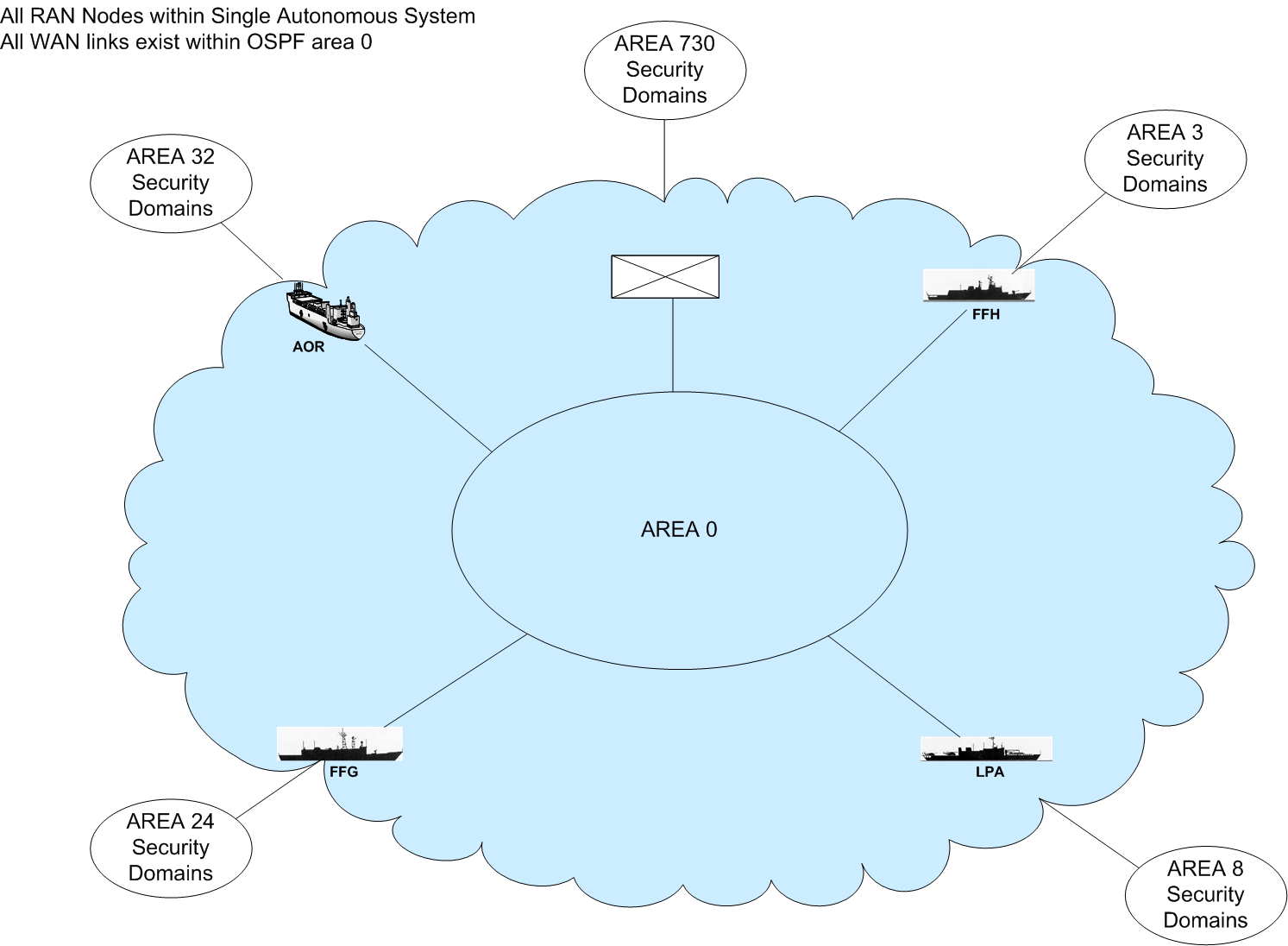
By OSPF convention, Area 0 (zero) or 0.0.0.0 represents the core or backbone region of an OSPF network. Each CRN node will connect to Area 0 and will also have its own specific Area identification. The CRN areas will each contain the associated classified networks or CCs that are connected at each particular CRN. Each CRN node will have a direct or virtual connection to the backbone OSPF area. Each node will also maintain separate link state databases for its specific Area and summarised routes for all areas in the network. This OSPF approach minimises the network discovery and update management traffic on the WAN, with only a single summary route being sent from each node to OSPF neighbours.
With OSPF, each node gathers link state information from available routers and constructs a topology map of the network. The topology determines the routing table presented to the internet layer—which makes routing decisions based solely on the destination IP address found in IP packets. OSPF detects changes in the topology, such as link failures, very quickly and converges on a new loop-free routing structure within seconds.
An alternative to IP based OSPF is the use of a multi-protocol label switched (MPLS) network. MPLS works by prefixing packets with an MPLS header, containing one or more labels called a label stack. Packets are switched according to a label look-up, instead of looking up IP addresses in a routing table. Routers in an MPLS network regularly exchange label and reachability information with each other to build a complete picture of the network. This is then used to forward packets.
MPLS defines the concept of traffic engineering (TE) by extending the OSPF RSVP mechanism. It allows users to constrain routes through a network based on bandwidth and any other relevant link attributes. This results in the shortest path route with available bandwidth and any other defined characteristics being selected.
If there is a network element failure and recovery mechanisms are used at the IP layer, restoration may take several seconds or possibly minutes for high latency links. This would be unacceptable for real-time applications such as VoIP. In contrast, MPLS allows the allocation of a primary and one or more secondary paths providing fail-over protection that meets the requirements of real-time applications—with recovery times of less than 50 ms.
Applications for crn
1 maritime environment
1 introduction
Thales Australia was awarded the SEA 1442 Phase 3 project [4] in February 2006, and this project is now in the installation and support phase. The SEA 1442 system architecture design is consistent with the guidelines set out in the Allied Communications Publication (ACP) 200 [5] for the Maritime Tactical Wide Area Network (MTWAN) environment. The MTWAN architecture provides an effective evolvable capability that is shaped to meet the future communication needs of naval forces and is aligned with future NCW requirements. Under the project, fifteen major Australian fleet units will be fitted with MTWAN capability—along with a shore facility at the Fleet Network Centre (FNC) and other training and support facilities.
2 architecture
Figure 2 shows the system architecture for the SEA 1442 MTWAN Mission System. It shows a ship system node and a shore system node that are interconnected through multiple bearers and the public domain network (PDN).
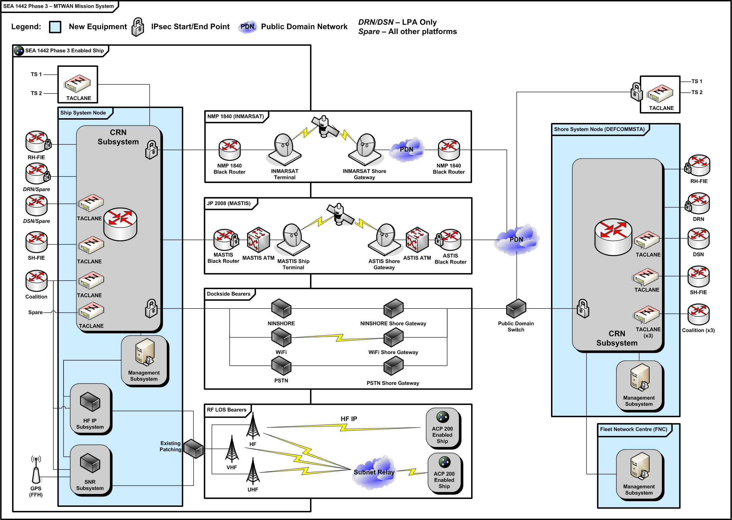
Each node has multiple security domains or CC networks. These include TS (Top Secret), RH-FIE (Restricted High—Fleet Information Environment), DRN, DSN, SH-FIE (Secret High—Fleet Information Environment) and Coalition. Information confidentiality has been achieved using Taclane data cryptos for the TS, DSN, SH-FIE and Coalition and IPSec for the DRN and RH-FIE (COMSEC protection). The router within the CRN also uses IPSec for link encryption before sending data to bearers (TRANSEC protection).
Bearers identified in Figure 2 include SATCOM bearers such as NMP 1840 INMARSAT and JP 2008 Maritime Advanced SATCOM Terrestrial Infrastructure System (MASTIS), dockside bearers such as shore, WiFi and PSTN gateways, and RF LOS bearers such as HF IP and Subnet Relay (SNR).
The MTWAN system can be managed from onboard ship or from ashore. The management of the Communication and Information System (CIS) on the ship is normally the responsibility of the ship’s communication operators. The operator at the FNC also has the ability to configure network devices on the ship and monitor the performance of those devices. This operator will typically have a high level of expertise that is available to support operators onboard ship when required.
3 properties
The MTWAN is fundamentally compliant with the essential PCN properties. This includes loose coupling between the information and infrastructure domains, information protection and confidentiality, QoS capabilities provided by the infrastructure domain, high infrastructure survivability, availability and resiliency, and black transport of information within the WAN infrastructure.
Figure 3 shows how these properties have been implemented. There are three major components for the MTWAN CIS—the bearer subsystems, the CRN, and the Integrated Management Environment (IME).
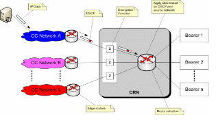
As shown in Figure 3, a DSCP value is added into the IP packet header at each source network exit point before the traffic is transported to the data crypto to enable QoS management. The source network and DSCP markings are used to discriminate the categories of data and enforce QoS requirements within the CRN.
A major function of the CRN is the integration of multiple communication bearers into a coherent backbone system to efficiently transfer information between ships and shore, while applying the required QoS. The enforcement of QoS is done by using a number of standard QoS features commonly found in COTS routers. Some of the features used include low latency queuing (LLQ) and class-based weighted fair queuing (CBWFQ).
To avoid congestion, traffic shaping is used to limit the rate of data leaving the CRN, and DSCP based weighted random early detection (WRED) is used to discard the lowest priority traffic first. The multi-bearer architecture and the automatic selection of bearers provide the high survivability and availability of the transformation infrastructure.
Besides the bearer subsystem and the CRN, the IME is also a major component of the MTWAN CIS. The IME system is based on COTS network management tools that monitor network devices using simple network management protocol (SNMP) and Internet control management protocol (ICMP). These protocols allow the status and performance of devices in the network to be monitored. The IME continuously monitors the operation of network devices to ensure that the services are always available to support any NCW operations. In addition, policy-based management (PBM) is a proposed model for the PCN policy management and this function is also implemented in the IME.
2 strategic environment
1 introduction
In the strategic environment, a highly capable nationwide network known as the Defence Wide Area Communications Network (DWACN) interconnects nearly 500 defence sites located in Australia and overseas. This capability will be upgraded under project JP 2047 Phase 3 from an Asynchronous Transfer Mode (ATM) to an IP core to overcome obsolescence and provide the scalability needed to deliver richer IP based video, data and voice content. The future network will be known as the Defence Terrestrial Communications Network (DTCN) and will deliver digital Terrestrial Communications Services (TCS).
JP 2047 Phase 3 will provide data distribution from the consolidated data centres to defence users. It will carry unified communications services including video, voice and data using Next Generation Desktop (NGD) delivery—and also extend these IP services to deployed forces through a number of tactical interfaces.
2 architecture
Figure 4 shows a conceptual system architecture view of the JP 2047 Phase 3 Mission System. It shows the data centres at the top, the bearer networks in the middle, and the Defence sites in the lower part of the figure. It also shows the Tactical Interface (TACINT) sites and the Defence Network Operations Centre (DNOC) and the Alternate Operations Centre (ANOC). At each node in the network, there is an instance of the CRN. Each node has multiple security domains or CCs that connect to the CRN through an edge router and a suitable encryption device that provides COMSEC. Traffic is aggregated in the CRN and then encrypted to provide TRANSEC, before being transmitted across the bearer networks.
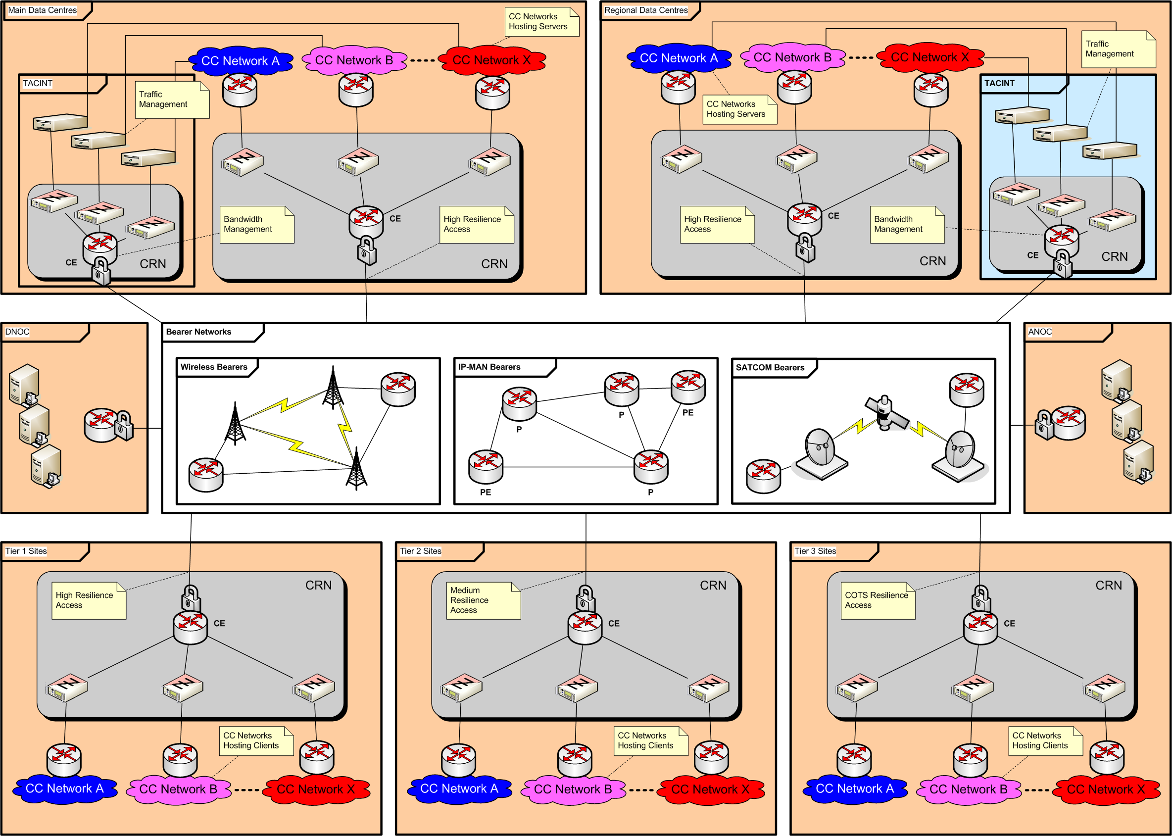
The primary bearer network would typically be a highly resilient MPLS based IP-MAN network provided by one or more telecommunication carriers. Backup links are available through wireless bearers such as 3G/4G and SATCOM.
The labels CE, PE and P relate to MPLS terms and represent customer edge, provider edge and provider routers respectively.
The connections from the CRN to the bearer networks can be high resilience, medium resilience or COTS resilience—depending on the importance of the particular site. High resilience would typically be implemented by redundant access to multiple bearers provided by redundant CE routers.
The TACINT sites are shown co-located with data centres for convenience, but they could be at any site where access to the CC networks is available.
Instances of the CRN may also be provided at the DNOC and ANOC, depending on the methods used to control and distribute the multi-domain management traffic.
All servers will only be hosted within the various data centres. The CC networks at the Defence sites are likely to only contain the various NGD client devices and the necessary distribution networks.
3 properties
Similar to the MTWAN example, the new DTCN architecture would comply with the essential PCN properties. This includes the same attributes for isolating the information and infrastructure domains and, importantly, the black transport of information within the WAN infrastructure.
Again referring to Figure 3, source CC network and DSCP marking methods can be used to support QoS decisions within the CRN. In the DTCN case, QoS is not likely to be an issue with the high capacity available within the IP-MAN. However, congestion will be an issue for the TACINT and the wireless or SATCOM backup links, so the COTS TM and BM techniques previously described will be needed.
As for the MTWAN, the CRN provides the capability to integrate multiple communication bearers into a coherent and highly available backbone system.
Through the PCN based CRN concept, the new DTCN should provide the following capability improvements:
- Protection from attack on carrier layer 2 and 3 (Ethernet VPLS/VPWS and IP VPN) transport networks.
- An improved ability to effectively use alternative transmission sources.
- A standardised clearly defined interface to deployed forces and the networks of other nations (tactical interface).
- A path for growth in bandwidth and capability requirements, including the ability to provide bandwidth and QoS guarantees through SLAs.
- Routing enhancements to allow for optimal path instead of traditional shortest path first—currently managed by artificially setting costs to ensure routing takes the manually determined ‘optimal path’.
- Improvements in managing changing requirements and operational scenarios.
A major component of the new DTCN will be an integrated management capability. This is likely to be based on a layered service oriented architecture made up of element management components and network management components—building up to a high level Operational Support System (OSS). Cross domain solutions (CDS) will provide the ability to reach across the range of CC networks and transport domains to give an integrated system wide picture. The management layer could also be used to provide feedback from the black core network to the red traffic management functions to support high levels of network efficiency.
3 land environment
1 introduction
In the tactical land environment, communication services are provided by the Parakeet system. This will be replaced by the Battlefield Telecommunications Network (BTN) element of the Battlespace Communications System (Land) or BCS(L) under Project JP 2072 Phase 2B. The system will be upgraded from one that is primarily focused on delivering voice to one that delivers converged IP voice, video and data. The project scope includes a suite of deployable communication nodes and strategic tactical interfaces. Suitably scaled and deployable communication nodes will be provided for the force, formation, unit, command signal detachment and liaison officer levels to support a large number of deployed users. These nodes are required to support operations for fixed, halted, paused and mobile conditions.
2 architecture
Figure 5 shows a conceptual system architecture for the JP 2072 Phase 2B BTN Mission System. It shows a series of communication nodes and—similar to the maritime and strategic network cases—the tactical land architecture uses a CRN at each communication node. This provides the means to aggregate data flows from the CC networks and access to multiple bearers. COMSEC is provided with an appropriate encryption device between the CC network and the CRN, and TRANSEC is provided for each of the bearer links.
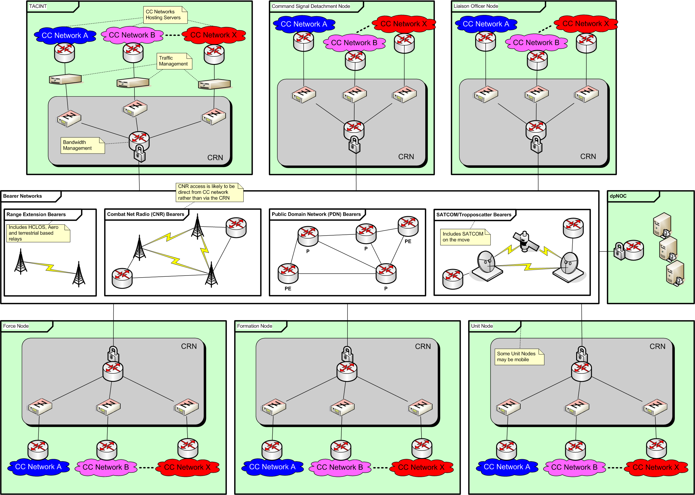
In a typical deployment operation, access back to the strategic DTCN will be provided via the TACINT nodes that extend services to deployed users through SATCOM or available PDNs. The TACINT is likely to include the TM and BM functions to manage QoS for the limited bandwidth SATCOM links. Each node may have one or more CC networks to implement the required security domains to support operations—including the usual DRN, DSN and possible coalition networks.
Bearers include SATCOM, troposcatter, PDNs, combat net radio (CNR) and range extension bearers.
The BTN system can be managed from the deployed NOC associated with the force, formation or unit nodes – or from the strategic DNOC. This will include the capability to monitor and configure all the communications and networking assets based on an overall communications plan, including spectrum management aspects. The operator at the DNOC will typically have a high level of expertise that is available to support the deployed operators when required.
3 properties
Similar to the MTWAN case, the new BTN architecture would be fundamentally compliant with the essential PCN properties. This includes the same attributes for isolating the information and infrastructure domains and black transport of information within the WAN infrastructure.
QoS within the transport networks will be critical for the constrained BTN bearers where traffic congestion is highly likely. Suitable techniques for prioritising traffic will be necessary to deliver essential services. To some extent, this can be achieved using DSCP and source CC network marking methods that will support QoS decisions within the CRN. As discussed in Section 2.3, using a method of providing feedback from the black side BM through to the red side TM will extract higher levels of efficiency from the limited bearer capacity available.
The management capability envisaged for the BTN is far greater than managing the CRN alone, as is the case for the MTWAN. The BTN is expected to provide an end-to-end management capability that will reach across several security domains in a similar way to the DTCN. This is likely to involve CDS and data diode elements as key infrastructure building blocks in the architecture.
Possible uses of the crn
1 introduction
This section provides three examples of application layer uses of the CRN, beyond the networking layer examples already discussed, that illustrate its flexibility and operational utility.
2 connectivity of local area networks
The fundamental application of the CRN is to provide a means of interconnecting separated local area networks (LANs) that operate at the same security level—such as the CC networks in all of the architecture diagrams. This effectively provides a virtual network that allows users to easily exchange information over WAN links. As a result of convergence to everything over IP driven by rapidly developing commercial technologies, users are able to exchange a full range of unified services including voice, video and data using standard COTS capabilities—but still be secured by high grade military encryption.
This advancement of capability is likely to continue as WAN bandwidth increases and processing power increases, and it will start to challenge stovepiped military Tactical Data Links (TDL). For example:
- A TDL typically requires significant engineering/configuration to enable military units to join the network. CRN does not because it is based on IP and provides inherent interoperability.
- A TDL does not allow information from non-participating units to be shared. Information sharing is limited to those units inside the TDL, and any external information must be garnered using other communications means—and then integrated and merged manually.
- CRN provides access to all information sources, whereas TDL merely allows participating units to share information in their own combat data/management systems.
For SEA 1442 Phase 3, the capability is already being extended to integrate and extend IP based voice services from the ship to shore.
3 maritime combat system training
Once the MTWAN capability was fitted aboard the upgraded Adelaide Class FFG ships, one of the first services connected was the onboard training system (OBTS) environment using the IP based Distributed Interactive Simulation (DIS) interface. This allows the ship to be linked to shore based training facilities so the ship’s combat team can participate in comprehensive and high fidelity training activities while the ship is alongside or at sea.
Effectively, the combat system training environment on board is now one of the CC networks that exchanges information across the WAN.
This is a good example of how the inherent flexibility within the CRN has been put to use to significantly enhance the training capability of the ship’s combat team—plus it was accomplished with relative ease compared with non-IP based systems.
4 anti-submarine warfare
The proliferation of highly capable diesel-electric submarines with reduced self noise, air independent propulsion and anechoic cladding has significantly reduced the detection capability of existing platform centric operations. The task is made even more difficult by the often complex local environmental conditions, especially those found in littoral regions.
Anti-submarine warfare (ASW) detection opportunities are often fleeting and only partial tracking is possible. Coordinating assets to interrogate such contacts requires the exchange of information with other platforms. The MTWAN provides the networking infrastructure to facilitate this exchange. The ASW data shared over the MTWAN can include time synchronization, derived from the accurate timing systems of the relevant sensor networks associated with the active acoustic transmission events. This is a key enabler for performing multi-static detection and localization.
The resulting ability to have a shared view of the operational environment provides a way of better evaluating the ASW engagement. The combination of multi-sensors can be used to develop a pre-track, thereby enabling a track-before-detect capability. The potential to correlate and detect a pattern of intermittent contacts and observations, or events over an extended period, is a powerful tool—indeed a ‘force multiplier’—that increases the capability to detect and prosecute an undersea threat.
Conclusion and recommendations
In this paper, we provided an overview of the CRN concept and discussed how this is an important architectural building block for the Australian Defence SNA and is aligned with the approach proposed by the NATO PCN.
The CRN provides a flexible infrastructure to support future highly dynamic network centric operations. The loose coupling between the infrastructure and information domain separates the protection of information confidentiality from the protection of the availability of the transport networks. While the information confidentiality and protection is provided by each security domain (or coloured cloud) respectively, the protection of survivability and the availability of the transport infrastructure is provided by the CRN. This separation of the information domain from the infrastructure domain not only benefits users (Defence), but also the carrier and service provider operators—from both a flexibility and security perspective.
We also discussed how the CRN concept can apply to three major network domains—the maritime MTWAN, the strategic DTCN and the tactical BTN. We then provided two application layer examples of how the CRN is already contributing towards NCW capability and one future example for ASW.
The CRN approach should be considered as a key enabler for the Defence SNA initiative.
References
[1] Australian Government Department of Defence, Single Information Environment, 2010.
[2] G. Hallingstad and S. Oudkerk, “Protected Core Networking: An Architectural Approach to Secure and Flexible Communications”, IEEE Communications Magazine, November, 2008, pp. 35–41.
[3] Australian Government, Department of Defence, Network Centric Warfare (NCW) Roadmap, 2007.
[4] Defence Material Organization, SEA 1442 – Maritime Communications Modernisation, http://www.defence.gov.au/dmo/esd/sea1442/sea1442.cfm#ph3.
[5] Allied Communications Publication (ACP) 200 (A), Maritime.