
Volume 14, Number 2, July 2011
Design Of A Laser-Warning System Using An Array Of Discrete Photodiodes—part Ii
- * Laser Science & Technology Centre, Metcalfe House, Delhi-110054, India.
- ** Defence Institute of Advanced Technology, Girinagar, Pune, India.
Abstract
Modern warfare includes extensive use of laser-based devices and laser-guided weapons. This large-scale use of laser-based systems means that all weapon platforms are vulnerable to attack by laser-guided munitions (LGM). Such a situation emphasises the importance of timely detection and recognition of laser threats. This necessitates that friendly platforms are equipped with a suitable laser-warning sensor that will provide timely information about the incoming laser threat with a high level of angle-of-arrival accuracy so that a suitable countermeasure action can be initiated against it. This paper (Part II of a two-part series of papers) discusses the design of the electronic processing module of a laser-warning system (LWS) having an opto-electronic front end designed using an array of discrete photo-diodes (the design aspects of, and test results for, the opto-electronic front end has been discussed in the first part). This is followed by a brief discussion on its simulated evaluation process and the test results for the determination of the angle of arrival and PRF of a laser threat.
Introduction
Processing of the electrical signals generated by the array of photodiodes is very critical since signals obtained from the photodiodes are very narrow (with a pulse width of 10 ns) and the amplitudes are also varying (as a result of variation in ranges and variation of laser power). Apart from the signals generated by the photo-diode array, there are many other aspects which need to be considered while designing the processing electronics of the LWS.
Design requirements
The laser used in most battlefield laser-based devices such as laser range finders (LRF) and laser target designators (LTD) is invariably a Q-switched solid-state laser. Although each of these laser-based systems has its own characteristics, all of them use either a single pulse or a stream of very narrow laser pulses with pulse widths in the range of 5–10 ns. In a typical battlefield scenario, the laser pulse can arrive at any time without any notice and can last only for 5–10 ns. Hence the LWS needs to react immediately and read the information from all of the elements of the photodiode array within this small time interval without the help of any external trigger input in order to provide a single-pulse detection capability. Hence the most critical requirement of an LWS is to have a very high-speed analogue signal processing circuit at the interface of the opto-electronic front end.
The next most critical requirement is the development of a digital logic controller that processes the information received from the analogue signal processor and applies an algorithm to display the angle of arrival of the laser threat with an accuracy better than ±3º and pulse repetition frequency (PRF) code with an accuracy better than 1 μs. The angle of arrival accuracy of ±3º is good enough for all defensive countermeasure systems being employed as an active protection system on armoured fighting vehicles (AFVs). The requirement of PRF code accuracy better than 1 μs occurs because all of the contemporary laser designators are coded with a PRF code where pulses are at least 1 μs apart in the time domain.
Another important requirement is the rejection of false alarms. A false alarm is the probability of the sensor indicating the presence of a laser threat when a laser threat is not actually present, or is present from some different direction. Laser light scattered from the atmosphere and reflected from the platform itself is one of the problems that needs to be overcome in order to reduce the false alarm rate.
Identifying the impinging laser threat type is also very important. This can be done by measuring the PRF. A laser range finder can employ a single pulse, whilst laser designators rely on a pulse train with a definite PRF. An internal database helps in further identifying the designator type of threat as known or unknown if the PRF is measured with the desired accuracy.
An LWS must also possess the capability to deal with multiple threats in the battlefield. It should be able to manage multiple threats, occurring with delay time, identifying direction-of-arrival and type of each threat. However, the capability to reject reflected beams restricts the multiple-threat-handling capability. Hence one needs to optimize the processing algorithm.
Analogue processing module
The block diagram of the laser warning sensor is shown in Figure 1 and each block is described in this section.
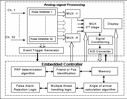
1 analogue processing module
The analogue processing of the electrical signals generated by the photodiodes is critical since signals obtained from the photodiodes are very narrow and the amplitudes are also varying. In order to process such signals, the devices chosen must meet the necessary slew rate and small signal bandwidth criteria. In the adopted design philosophy, the pulse width of the signal is stretched while retaining its amplitude information for determining the direction-of-arrival of the incident laser pulse. The stretching of pulse width serves two purposes: first, it helps in providing sufficient time for the processor to scan and read all the channels; and second, it enables slower and comparatively lower-cost devices to be used for further processing. The circuit is similar to a peak detector circuit with values carefully chosen so that it should not hamper its overall bandwidth. Hence stretching has been done in three stages where the load capacitance has been increased gradually to meet the required amount of stretched width. The op-amp chosen for the purpose has a slew rate of 325 V/μs and gain bandwidth product of 120 MHz. It is a unity gain stable op-amp and is specially designed for driving unlimited load capacitance. There are 32 such identical channels (circuits) to take care of electrical signals from the 32 photo detectors employed as an 8×4 matrix in the opto-electronic front end (discussed in Part I of this paper).
After stretching the pulse, these 32 channels are multiplexed through a two tier analog multiplexer circuit. This saves on use of additional hardware and hence the cost of the system. As the pulses are already stretched, it gives the multiplexer sufficient time to sample all the channel amplitudes without significant variation in the actual amplitude for each pulse. The multiplexed output is fed to an analogue-to-digital converter (ADC) for digitizing the amplitude of each of the 32 channels. The ADC chosen for the purpose is a pipeline type 8-bit ADC having 60 MSPS speed of conversion and analogue bandwidth of 120 MHz. The 8-bit digitized output is fed to the digital controller, wherein amplitude information of all these channels is processed by applying the weighted centroid algorithm (explained in the next section). This digital logic controller also generates the control signals for ADC as well as the addresses for the multiplexer.
2 event trigger circuit
The output of first stage of the pulse stretching stage for each of the channels is also fed to a comparator circuit. Each of the channel amplitudes is compared with a reference voltage. The reference voltage is set to be equal to the detection threshold. The detection threshold is chosen carefully so that it is lower than the amplitude of the signal produced when the weakest source is placed at the farthest range; at the same time it is higher than the maximum value of the noise voltage. The comparator output of all the 32 channels is fed to an OR-ing stage which generates a pulse when any of the channels receives a laser pulse. This pulse serves as an input to the digital controller as an event trigger and is used for two purposes. First, it works as a trigger which commands the controller to start generating the address for the multiplexer to scan and store all the channel amplitudes. Second, it is also used for calculating the PRF of the incident laser.
3.3 Embedded System Controller
The embedded system controller comprises micro controllers and its peripheral devices. It is the most important block of the laser-warning sensor. It performs the following functions:
- serves as input port for the 8-bit digital data for each of the 32 channels;
- scans all 32 channels in forward and backward direction and averages forward and backward scanned data values (to offset the errors arising out of any droop in the scanned channels) for all channels and saves them into memory for further processing;
- hosts the algorithm to calculate the angular direction-of-arrival;
- takes the decision for friend or foe identification after identifying the PRF;
- generates the data stream to the display device; and
- generates the output signal for the countermeasure system.
Since it has to carry out all these functions within a short time frame, a high-speed micro controller was chosen. The selected microcontroller operates at 100 MIPS throughput with on chip PLL. Due to its pipelined architecture, it executes 70% of the instruction set in one or two system clock cycles.
3.4 Angle-of-arrival Calculation Algorithm
The angle of arrival calculation algorithm adopted for each of the four laser warning sensor modules having field of view of 95° is as follows.
- The amplitude data from all the scanned channels are stored in memory.
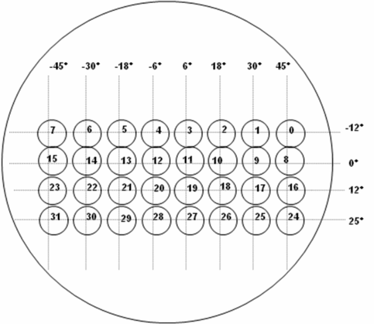
- Each channel and its assigned angular weight (as shown in Figure 2) both in azimuth and elevation are also stored in the form of a look up table.
- The algorithm first determines the channel corresponding to the maximum amplitude and retains all channels having peak amplitude more than 45% of highest peak amplitude. It rejects the remaining channels with less than 45% of the highest peak amplitude. This selection of percentage of 45% of maximum value is finalized after extensive testing of the LWS module. The LWS was tested for percentage values ranging from 25% to 75%.
- After amplitude based sorting, it employs an algorithm to reject all those channels being activated due to reflected and scattered radiation.
- The angle of arrival of the laser threat is calculated using the following formula:
Azimuth angle = (∑ Vi * Wi,azimuth) / ∑Vi
Elevation angle = (∑ Vi * Wi,elevation) / ∑Vi
where (Vi) is the voltage amplitude of the respective channels, (Wi) is the angular weighting of the respective channels and (i) is the channel number. In this way the algorithm calculates the angle-of-arrival in azimuth from –45º to +45º and elevation angle from –10º to +25º for each of the four sensors.
5 determination of prf code
Whenever a valid laser threat pulse arrives, the event trigger circuit generates a trigger pulse. The microcontroller uses these trigger inputs to calculate the PRF. The microcontroller fixes a time stamp corresponding to each event and stores the time T(i) in a register. The microcontroller takes the successive difference of these events and calculates the PRF code with an accuracy better than 1 µs when a crystal of high stability is used along with a microcontroller operating at 100 MHz. The accuracy of the PRF code also depends upon the stability of the processing electronics that generate the trigger pulse corresponding to the incident laser pulses. If this PRF code matches the predefined codes stored in the memory, then it is a friendly code; otherwise it is an unknown code. Figure 3 describes the philosophy of the calculation of the PRF code, or pulse repetition time (PRT).
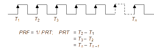
6 multi-sensor configuration
Until now, the description has been given for the design of an individual laser warning sensor offering field-of-view from –45º to +45º in azimuth and from –10º to +25º in elevation providing angular accuracy within ±3º (rms) over the spectral range from 900–1,600 nm. Development of a complete laser-warning system, which can be used as an electro-optic support measure (EOSM) on any AFV, mainly involves the integration of four such sensors in a multi-sensor configuration so as to give threat information for the complete 360º azimuth angle.
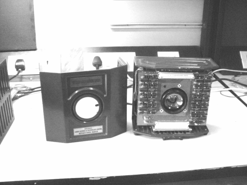
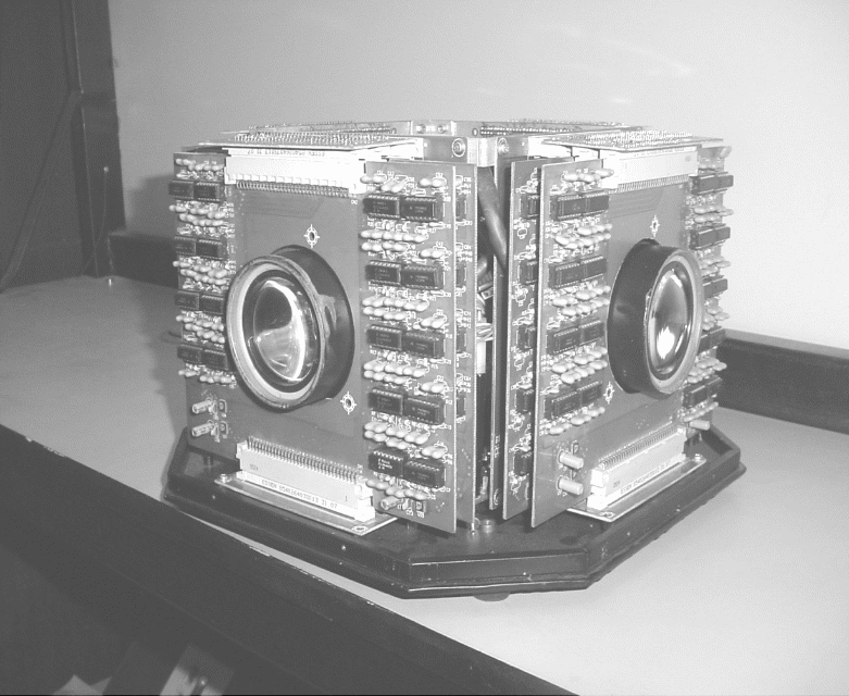
Multi-sensor configuration of these sensors takes the individual angular input from all these four sensors. The multi-sensor (central) controller is now the master controller for these four sensors. The detailed schematic of multi-sensor configuration for the laser warning system is shown in Figure 4. The actual photograph of single sensor and multi-sensor configuration is shown in Figure 5 and Figure 6 respectively.
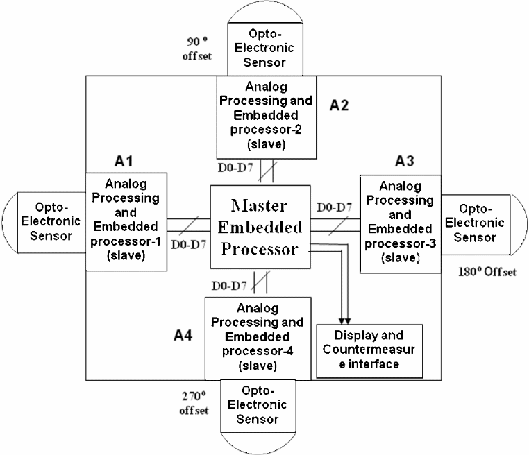
The heart of the system is a master microcontroller that controls the slave micro controllers of each of the four sensors. All four slave microcontrollers operate independently in terms of controlling the mux, ADC, storing of intensity (amplitude) information of the photodiodes and calculating the angle of arrival (within –45º to +45º in azimuth). The fetching of the data from slave to master is controlled by the master controller. Slave controllers pass on the angle of arrival information along with the peak amplitude information to the master controller. At the master microcontroller, the required calculations in terms of adding of offset, deciding on the valid threat and the display interface and countermeasure interfaces are generated.
The master microcontroller controls the timings and the fetching of data from individual sensors. Further, it identifies the peak value of threat and also identifies to which sensor it belongs. It then displays the azimuth value corresponding to it after addition of a predefined offset corresponding to location of the sensor with respect to a reference sensor. Offset is added in increasing steps in a clockwise direction from the reference.
Experimental set-up and test results for detection of angle-of-arrival
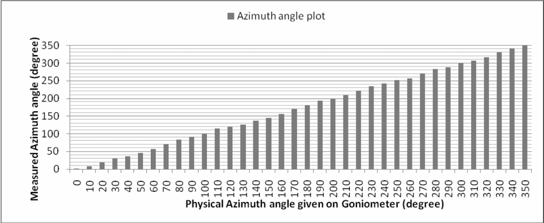
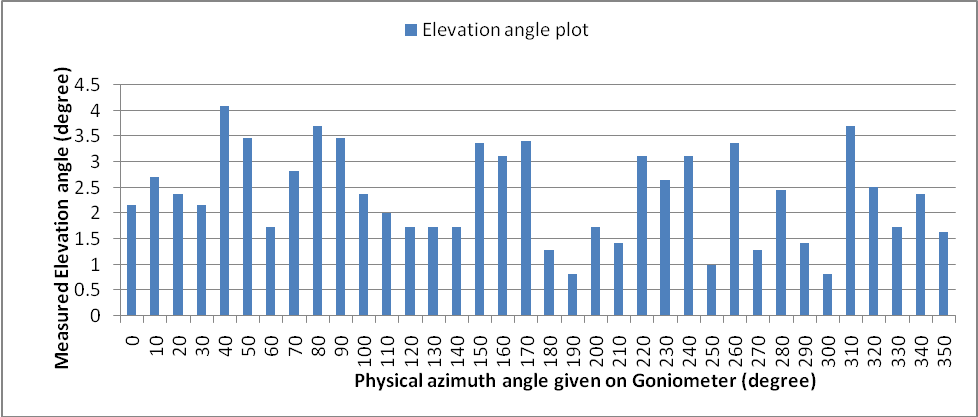
The sensor was tested with laser range finders having laser wavelengths at 1064 nm and 1540 nm. Both the sources emit a Q-switched laser of 10±3 ns pulse width having energy of 10±3 mJ and having a divergence of about 1 mrad. The in-house testing was undertaken by simulating a range of 1 km, 2 km, 3 km. and 4 km by expanding the laser beam using a diverging lens. The expanded beam was not collimated during this particular experimentation and had little divergence for short simulated ranges. For longer simulated ranges, the divergence was negligible and was near-parallel light at the central point of expanded beam where the sensor (photodiode array) was placed. Further, since in the proposed design, the photo-diode array was not placed at the focal plane of the lens, a small amount of divergence in the beam did not produce any significant deviation in the result as obtained in the present experiment. The sensor was placed on a digital goniometer. Before starting the test, the sensor was aligned with the zero degree reference line in both azimuth and elevation. The laser was fired and readings of the measured azimuth and elevation angle were recorded. A set of three readings were taken at the same position by firing the LRF three times at an interval of 10s. The LWS was then rotated by 10° and next set of three readings was recorded after firing the LRF three times. Further readings were taken by rotating the sensor in steps of 10° and by repeating the same process. After taking all the readings starting from 0º and ending at 350º, the rms value of each set of three readings were calculated and plotted as shown in Figure 7 and Figure 8. The reading was taken for a fixed elevation angle of 0° and a simulated range of 4 km. Figure 9 shows the corresponding error plot.
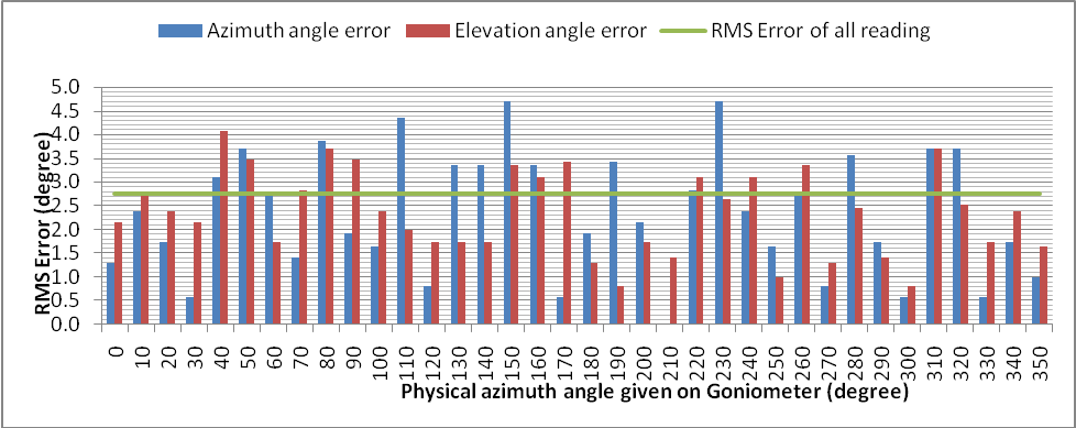
Similar sets of readings were taken for complete 360º azimuth angle after changing the elevation angle in steps of 5º from –10º to +25º. Readings corresponding to each set of elevation angle showed similar trends.
Experimental set-up for prf determination
Readings for PRF were taken by replacing the laser range finder with laser target designator (LTD) in the previous set-up. While taking readings, a code is first set in the LTD. One needs to set the code in the LTD in milliseconds with three decimal digits. Hence the LTD can be programmed to change the PRF code (PRT) in steps of 1 µs ranging from 05.000 ms to 50.000 ms. Readings were taken at random codes to evaluate its PRF determination accuracy. The LWS displayed exactly the same code as programmed in the LTD all time which indicates that the LWS detects the PRF code with accuracy better than 1 µs. Table 1 shows a few sample readings taken for PRF code determination.
| Sample | PRF code set on LTD (ms) | PRF code displayed on LWS (ms) |
|---|---|---|
| 1 | 06.000 | 06.000 |
| 2 | 10.274 | 10.274 |
| 3 | 20.500 | 20.500 |
| 4 | 30.333 | 30.333 |
| 5 | 38.888 | 38.888 |
| 6 | 44.567 | 44.567 |
| 7 | 48.123 | 48.123 |
Conclusion
The readings taken for the detection of angle of arrival shows that the designed LWS detects the direction of arrival with an rms error of less than 3º for the complete 360º azimuth angle coverage and elevation coverage from –10º to +25º.
The test results of PRF code determination indicates that the designed LWS detects the PRF code of the LTD correctly up to the third decimal place when code is set in ms. Hence it is evident that the accuracy of detection of PRF code (PRT) is better than 1 µs.
Acknowledgement
Authors are thankful to Sh. Ajay Rathi, Sh. Vikhen Kumar, Ms Dev Kumari and Sh. Bhola Nath Bera for all their support and help during the experimentation.
References
[1] “Type 453 Laser Warning Receiver (United Kingdom)”, Janes Avionics, Airborne Electronic Warfare System, April 2009.
[2] “Shtora-1 Active Defence System”, Defence Update, International Online Defence Magazine, Issue 1, 2004.
[3] “Selex Communications RALM/02 Laser warning receiver (Italy)”, Janes Armour and Artillery Upgrades, July 2008.
[4] “Thales Cerberus II Integrated Laser Warner and Countermeasure System (United Kingdom)”, Jane’s Armour and Artillery Upgrades, July 2008.
[5] Sushil Kumar, A.K. Maini, V.B. Patil and R.B. Sharma, “Laser Warning Sensor Assisted Countermeasure System”, Proceedings of the First International Conference on Electronic Warfare, EWCI-2010, pp. 315–318.
[6] M. Al-Jaberi, M. Richardson, J. Coath and R. Jenkin, “The Vulnerability of Laser Warning Systems against Guided Weapons Based on Low-Power Lasers”, Parts 1–4, Journal of Battlefield Technology, Vol. 9 and Vol. 10, 2006–07.