
Volume 14, Number 2, July 2011
Influence Of An Armoured Vehicle’s Hull Structure On Absorption Of Blast Energy
- * Department of Mechanics and Applied Computer Science, Military University of Technology, Faculty of Mechanical Engineering, Kaliskiego Street 2, 00-908 Warsaw, Poland.
Abstract
The thesis presents an initial concept of modification and calculation of a light armoured vehicle’s hull structure. It aims at enhancing the protection of the crew through the modification of the base-plate armour. The results of numerical calculations for the elements of an armoured vehicle structure exposed to the impact generated by the explosion of an underbelly blast mine are presented.
Introduction
Light armoured vehicles are commonly used in many operational environments, mostly due to their operational independence, high mobility and firepower in all weather and terrain conditions. Therefore, light armoured vehicles are exposed to most of the direct and indirect fire means at the disposal of opposing forces, including barrel artillery, rocket systems, anti-tank mines, and weapons of mass destruction. Contemporary technical and tactical requirements determine the shape of an armoured vehicle’s hull in order to ensure their high survivability in the battlefield, including:
- geometry and shape, ensuring the highest (for a respective class) protection level;
- high endurance to external dynamic loads; and
- good protection of the crew and internal equipment against large mines.
Protection for the crew and internal equipment against adversary weapon systems is provided to a certain extent by the basic vehicle armour. Current technology allows for some parts of vehicle’s armour to be shaped and configured both with regards to material and geometry.
A major problem, however, occurs when effective protection from mines is needed for the crew and internal equipment [1]. Modelling the phenomena of explosion and blast wave propagation is difficult due to their physical complexity. Contemporary development of numerical techniques has allowed for the simulation of many phenomena including the explosive material burning process and the impact of a blast wave. Considerable attention is paid to this subject in the literature—see for example [4–6].
The necessity for continuous enhancing passive protection [2,3] of constructions gives rational arguments in the research of new solutions such as protective layers. This paper presents an effort to employ blast wave load modelling to the design process using the technique of coupling the flow and the structure.
To couple the interaction between liquid and structure the ALE (Arbitrary Lagrange Euler) algorithm was employed. The method is a standard implementation of the MSC Dytran software [7]. For the equations of movement and pressure caused by the detonation an identical scheme of integration over time was used.
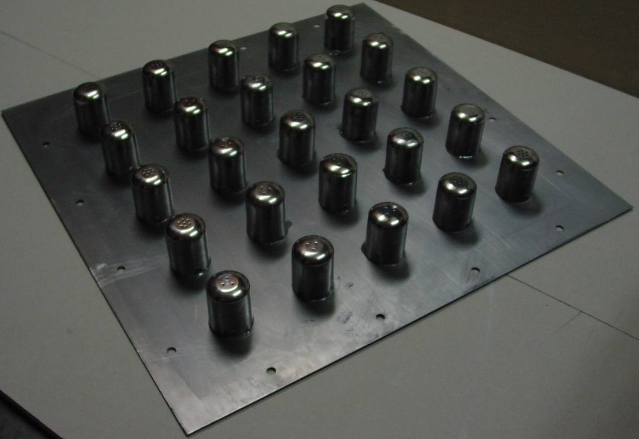
The aim of the numerical research presented in this paper was to investigate the influence of the shape of an energy-absorbing element and the material utilized on the energy absorption of the entire system hit. While preparing the numerical models, the results of the experiments conducted were used. Figure 1 presents the energy-absorbing elements utilized during the experimental research for the verification of numerical models.
General description of numerical models
The numerical analysis was conducted for two models:
- Model 1 – part of vehicle’s base plate (8 mm steel shield) without any additional protection.
- Model 2 – combined two steel shields of 8 mm and 1 mm, with energy-absorbing elements made of funnels having a 0.25 mm thick wall in between.
The blast wave products are modelled as a pressure wave propagating in a regular cube-shaped channel with simulated boundaries taking into account the deformation of shield simulating the bottom of a vehicle. The domain in which the explosion propagated was modelled using Euler elements type Hex 8, characterized by properties of perfect gas with heat capacity ratio γ = 1.4 and density of atmospheric air of 1.2829 kg/m3. Shields and steel protective elements were modelled using Lagrange elements type Shell Quad 4.
Model 1 numerical analysis results
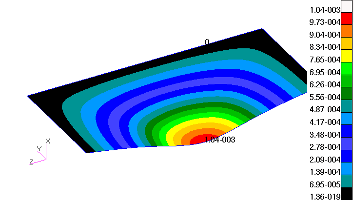
Model 1 was a steel shield exposed to the impulse of pressure presented in Figure 2. The shield deflects the load in such a manner that the plastic deformation of the plate commences along attached sides of the plate (from the side’s middle towards the corner), and then the deformation of the entire plate takes place. The final phase of the plate’s extension is the highest growth of plastic deformation which takes place in the middle of the plate. Final stage of the deformation of the plate is shown in Figure 3.
![The final stage of deformation of Model 1 [mm].](/journals/journal-of-battlefield-technology/volume-14/issue-02/assets/14-2-1-barnat/figures/figure03.gif)
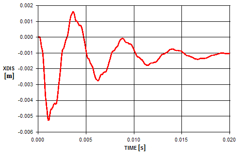
Figure 4 depicts the basic plate’s (8 mm thickness) centre displacement as a function of time. Maximum dislocation reached 0.0051m. Then, the plate vibrated and the investigated node stabilized at the permanent deformation of 0.0011m.
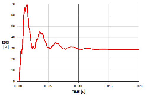
The plot of energy deflection over time is presented in Figure 5. The maximum value of 68J was achieved for Model 1 during the initial period of load. With the increase of the pressure, the plate was subjected to very strong extension. After 0.007s, the deflection energy stabilized at 30J. This energy increased similarly to displacement over time from 0s to 0.001s. The maximum acceleration achieved for Model 1 was 0.6e6 m/s2.
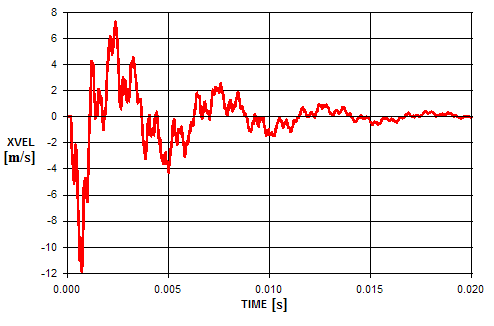
The velocity graph is presented in Figure 6. The maximum velocity of middle node in Model 1 was 12 m/s for the time 0,001s. During a subsequent stage of analysis the damping of velocity took place. The maximum acceleration for the centre node reached the value 100,000 m/s2.
Model 2 numerical analysis results
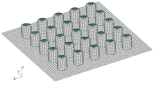
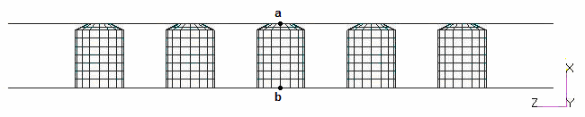
Model 2, presented in Figure 7, consists of three parts: the first upper plate; impact energy absorbing elements; and the bottom second plate—protected. Points a (on the upper plate) and b (on the bottom protected plate) are of particular interest. These points were located on the intersection of two symmetry surfaces of Model 2. There were 25 energy-absorbing elements of cylindrical shape combined with a truncated cone capped with a lid.
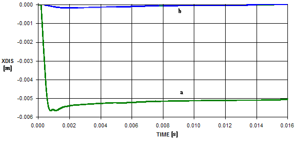
Particular elements of Model 2, presented in Figure 7, were modelled with 10200 shell-type elements and 14991 nodes. Energy-absorbing elements had a 0.25 mm thick walls. Figure 8 presents the displacement relative to the origin of points a and b as a function of time. Vertical axis describes the dislocation (m), while horizontal represents the time (s).
Analysis of this diagram shows a very high level of stiffness of the coating in the initial linear-resilient deflection stage. In the initial phase of the analysis node a (on the upper plate) moved by 0.056 m. The dislocation of this point continued to 0.0021s, when the point moved by 0.005 m. Point b, located at the middle of bottom protected plate, acted similarly to the real construction. The node moved by 0.0002m during initial phase of the analysis (at 0.0015s). The displacement of the point continued to 0.001s and then returned to the previous position. There is no permanent deformation of the bottom protected plate.
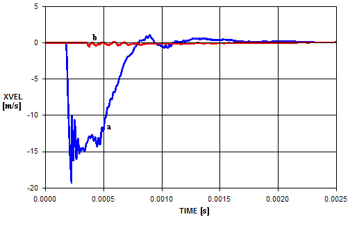
The velocity plots for points a and b are presented in Figure 9. As can be seen, the character of curves is similar to the displacement plots. During the initial period of analysis node a moved with the velocity of 19 m/s (for the time 0.00025s). On the other hand, point b moved with much lower velocity of 0.6 m/s (as measured at the time 0.001s). The highest acceleration was observed for point a with the value 2e7 m/s2 at 0.0003s. The maximum acceleration for point b reached 0.5e6 m/s2 at 0.0012s. After 0.0007s, both plates stabilized.
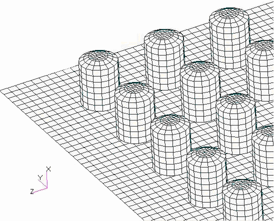
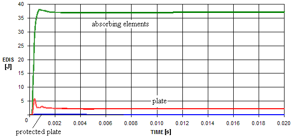
Figure 10 shows the dynamics of the deflection energy (for plastic scope) as a function of time. It is clearly visible that most of the energy was absorbed by energy-absorbing elements – 37J. Other components of the panel absorbed less: the plate absorbed 2.5J of energy, while the cones and protected plate took deflection energy of 0.1J.
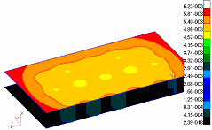
The results obtained during the analysis of Model 2 deformation (in metres) are presented in Figures 11 and 12. In both cases, the calculated values were presented as displacement maps on deformed structure.
Summary
The work presented in the article is a part of broader research on energy-absorbing elements. A model of the entire vehicle was used to define the shape and value of the pressure impulse. The ALE coupling method was utilized to combine Euler’s area with the vehicle’s model. The homogenous plate was tested and compared with a panel containing thin-walled energy absorbing-elements with a lid.
The results show that use of the plates in a panel stiffens the energy-absorbing elements. In addition, a comparison of both models centre nodes displacement was done and is presented in Figure 13.
The final displacement of Model’s 1 centre node reached 1 mm, which is a high value comparing to the 8 mm thickness of the plate. What is more, the permanent deformation prevents reuse of the plate. Structures with energy-absorbing elements (Model 2) act differently. There is no permanent deformation of the protected plate and the maximum displacement is twice lower than in Model 1. The deformation of the energy-absorbing layer is regular. Only the cone parts of the energy-absorbing elements were deformed by the impact, leaving the cylindrical elements intact. Protected plate is undeformed allowing for its reuse by adding a new panel.
Experience from contemporary conflicts shows that there are difficulties with estimation of the size of the charge that will be planted under the vehicle. The Iraq conflict indicates that vehicles are attacked by combined charges consisting of several anti-tank mines. This means that the energy-absorbing layers should be constructed for protection against large explosive charges. The goal is to create such a structure that would sustain at least two subsequent explosions of anti-tank mines.
References
[1] W. Barnat, “Transporter opancerzony Adi Bushmaster”, Myśl Wojskowa, Vol. 5, 2005.
[2] W. Trzciński, R. Trębiński, and S. Cudziło, “Investigation of the Behaviour of Steel and Laminated Fabric Plates Under Blast Wave Load, Part I: Experimental Approach”, V International Armament Conference, Waplewo, 2005.
[3] R. Krzewiński and R. Rekrucki., Roboty budowlane przy użyciu materiałów wybuchowych, Polcen, 2005.
[4] P.H. Thornton and R.A. Jeryan, “Crash Energy Management in Composite Automotive Structures”, International Journal of Impact Engineering, Vol. 7, No 2, 1988, pp. 167–180.
[5] W. Babul, “Odkształcanie metali wybuchem”, WNT Warszawa, 1980.
[6] E. Włodarczyk, Wstęp do mechaniki wybuchu, PWN, Warszawa, 1994.
[7] Dytran Theory Manual; LS-DYNA theoretical manual, 1998.
[8] W.E. Baker, Explosions in Air, University of Texas Press, 1973, Austin London.