
Volume 14, Number 1, March 2011
Design Of A Laser-Warning System Using An Array Of Discrete Photodiodes—part I
- * Laser Science & Technology Centre, Metcalfe House, Delhi-110054, India.
- ** Defence Institute of Advanced Technology, Girinagar, Pune, India.
Abstract
Present-day warfare includes extensive use of laser-based devices and laser-guided weapons. This large-scale use of laser-based systems has made all platforms more vulnerable to precision attack by laser-guided munitions (LGM). Such a situation emphasises the importance of timely detection and recognition of laser threats. This necessitates that friendly platforms are equipped with a suitable laser-warning sensor that would provide timely information about the incoming laser threat with a high level of angle-of-arrival accuracy so that suitable countermeasure action can be initiated against it. This paper (part I of II) discusses the design aspect of the opto-electronic front end of a laser-warning system (LWS). It highlights the technological challenges in the design of the opto-electronic front end of the LWS and gives a brief description of a unique design using an array of discrete photodiodes. The results are analysed to assess its suitability for a laser-warning system having angular accuracy of ±3º and field of view from –45º to +45° in azimuth and –10° to +25° in elevation.
Introduction
The lasers used in most of the laser-based devices (such as laser range finders (LRF) and laser target designators (LTD)). are almost invariably a Q-switched solid-state laser. Although at present, the most common is a Nd:YAG or Nd:glass type of solid-state laser with its emission around 1064 nm and 1054 nm respectively. Devices in the wavelength band around 1540 nm are also proliferating due to the relatively eye-safe nature of the output for the users of the equipment. The laser threat from an enemy can come at any instance from any direction and will remain detectable for only 5–10 ns in the case of an LRF. Hence, the laser-warning system (LWS) will need to detect and store all the information regarding the laser threat within this small time interval.
Modelling and simulation
In a battlefield scenario, any laser-based device is generally fired at the target from at least 500m. Hence the laser beam hitting the LWS can be assumed to have a planar wavefront that is, the incident beam may be considered to have rays parallel to each other. A lens focuses such parallel rays to a spot in its focal plane. The location of this spot depends entirely on the direction in which the rays are incident. An array of photodiodes placed at the focal plane of a converging lens can be used to detect the presence of laser beam and its direction of incidence by determining the position of the spot on the array. Figure 1 shows a lens focusing two laser beams in its focal plane.
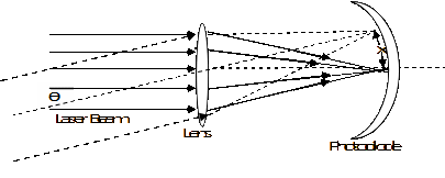
The beam parallel to the axis of the lens focuses on the axis whereas the beam incident at an angle θ to the axis gets focused at a distance x such that:
where f is the focal length of the lens. The required focal length of the lens depends on the angle of acceptance of the LWS and on the size of the photodiode array. Equation (1) can be rewritten as:
From (2) one may be tempted to increase the acceptance angle of the LWS by reducing the focal length—however, beyond a certain angle, it is not advantageous to increase θ. For large angles of incidence, astigmatism becomes important. By designing the lens properly, the astigmatism can be corrected partially but the lens design and fabrication becomes more complex as the acceptance angle is increased. In the proposed design, the acceptance angle, 2θ, of the lens has been kept equal to 95°. To cover 360° a set of four such systems can be used, each covering an angle of 90º with an overlap of 5º with the adjacent sensor.
Design of opto-electronic front-end assembly
The design of the opto-electronic front-end assembly is very critical for a laser-warning sensor. It is responsible for providing the desired field-of-view, spectral coverage, angular resolution, resistance-to-jamming, and capability to respond to very narrow Q-switched laser pulses of the order of 5–10 ns. Its design consists of a converging optical assembly followed by a two-dimensional array of photo-detectors having parallel readout capability and a high damage threshold. A high damage threshold is required as a counter-counter-measure to prevent it from being damaged by possible electro-optic counter-measure (EOCM) laser threats. A parallel readout capability is required as sufficient time is not available to generate a trigger pulse for serially sampling and storing of information from each sensor element.
Since a monolithic two-dimensional photodiode array having the desired spectral range (900–1600 nm), with a high damage threshold and provision for parallel readout is not available in India and is a banned item, a device with the same functionality has been made using discrete photodiodes. The photodiode array is placed with respect to the optical assembly in such a way so as to give the desired field-of-view, resolution, and resistance-to-jamming.
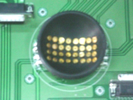
The design involves use of a converging lens assembly having a wide field-of-view (~95°) and use of individual photo detectors responding over the spectral range from 900 nm to 1600 nm. These discrete photodiodes are arranged in a two-dimensional matrix arrangement of 8×4 elements and are placed on a curved plane as shown in Figure 2. The curved focal plane offers the linear movement of the image for a normal converging lens. The curvature of the imaging plane is kept equal to the focal length of the lens assembly.
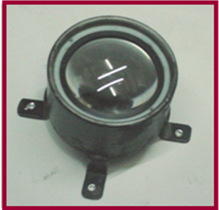
While choosing the parameters of the converging lens, factors such as wide field-of-view, astigmatism, and collection of laser intensity governed the design. In the proposed design, on one hand a large aperture is required to collect sufficient amount of laser flux when operating at the farthest distance (perhaps in excess of 6 km) using the weakest laser source (such as LRF) whereas, on the other hand, one also has to keep in mind that it should not be large enough to saturate the photodiodes when exposed to the strongest source (such as a laser designator) placed at the closest distance (500m for a typical battlefield scenario). A clear aperture of 50 mm served the purpose when a lens of focal length 25 mm is chosen to form a focal spot of 10 mm (under de-focused conditions) on the array of chosen photodiodes. The optics module is shown in Figure 3.
Again while choosing the photodiode, as the requirement of the LWS is to be able to detect both weak as well as strong optical signals of a very narrow pulse width, one needs to choose a photodiode with high responsivity, high dynamic range, wide bandwidth, and high damage threshold. Also, one needs to choose a photodiode covering a wide optical bandwidth (from 900 nm to 1600 nm) so that all types of LRF and laser designators can be detected. Keeping all these requirements in mind, a suitable InGaAs photodiode was chosen for the photodiode array.
The next most important aspect one needs to consider is the avoidance of dead zone. Dead zone is that situation in which the laser spot falls on the array in such a manner that none of the photodiodes in the array receives sufficient intensity to generate a valid pulse. Such a situation arises due to the interspacing of the active area of two adjacent photodiodes. In discrete photodiodes, the size of the active area is generally much smaller than the physical size of photodiode. Hence, to avoid the problem of dead zone, the diameter of the focal spot is kept slightly greater than √2 times the inter-element spacing of the photo detectors. In this condition, when the spot moves from one detector to another, at least one element (photo detector) will always remain illuminated. Additionally, this large spot size (resulting in lower power density) helps in improving the resistance to jamming and damage of the photodiodes.
The focal length of the lens, spot size, and the inter-spacing of the photo detector bear direct relationship to govern both the angular accuracy as well as the field-of-view. In order to have minimum number of photodiodes to cover the complete field-of-view of 95º while offering the angular accuracy of ±3º, the interspacing between the photodiodes chosen was about 7 mm. With this arrangement, one needed eight photodiodes in the horizontal plane to cover the azimuth angle of 90º when the focal length of the lens is kept at 30 mm. Similarly, four photodiodes are required in the vertical plane to cover the elevation angle of 35º. The curvature of the focal plane was made equal to the focal length of the lens (that is, 30 mm) and is placed in ‘under-focused condition’. The curved focal plane was made with nylon material having mounting holes for the 32 photodiodes in a 8×4 matrix form.
Test procedure and results
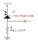
The designed opto-electronic front end was tested using two different LRF’s emitting at wavelengths 1064 nm and 1535 nm. The LRF emits laser pulses of energy ≈10mJ and a duration of 6 ns. In the test set-up, each of the photodiodes was connected in photoconductive mode as shown in Figure 4. The response was observed across the resistor connected to the photodiode.
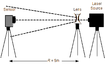
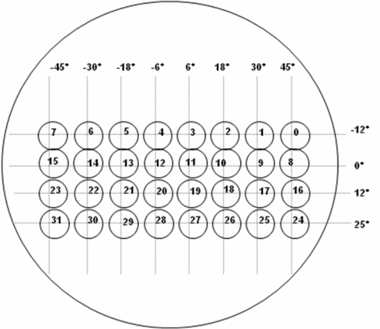
The experimental set-up is shown in Figure 5. The front-end assembly was fixed on a rotation platform. While taking readings, the front-end assembly was first aligned with the 0º axis of the LRF in both azimuth and elevation. The LRF was placed at a distance of 2m from the front-end assembly and its laser spot was expanded using a diverging lens to make a spot of 1m at the opto-electronic front end plane. This simulated a distance of 2 km (in terms of power density of laser) in open range for an LRF having divergence of 0.5 mrad. The front-end assembly was then rotated on the rotation platform and positioned at 45º in azimuth. The laser was fired and outputs of all the photo diodes of the two dimensional 8×4 matrix were observed and tabulated. The schematic of the array with each channel (photodiode) numbered from 0 to 31 is shown in Figure 6. The front end was then rotated through 3º in azimuth and reading was again taken and tabulated. This procedure was repeated for every 3º azimuth angle rotation of the front end starting from +45 to –45°. After taking all the readings in the azimuthal plane for a fixed elevation angle of 0°, the process was repeated after changing the elevation angle by 3° and a reading corresponding to all azimuth angles between +45° and –45° were tabulated in steps of 3°. The above process was repeated for all elevation angles in steps of 3° between –10° and +25° and the corresponding set of readings was tabulated.
Analysis and conclusion
From the tabulated data, it was observed that the laser spot moves from right most to left most column (channel 0 to channel 7) as the angle of incidence is changed from +45º to –45º in azimuth. For example, when the angle was 45º, the channel having maximum amplitude was channel 0 (right-most column). When the angle was rotated towards 30º, the most significant channel moved towards left (channel 1). When the angle was further rotated, the most significant channel moved further towards left. It was also observed that the voltage level of other active channels for each reading varied in a predictable manner. Similarly when the front end assembly was rotated in elevation from –10º to +25º, the channel having maximum amplitude moved from channel 4 (top-most row) to channel 28 (bottom-most row). It is evident from the obtained readings that the voltage level follows a fixed trend when the angle of incidence changes within the field of view of lens. Hence, based on this trend, an electronic processing module (as presented in Part II) can be developed to determine the angle of arrival with accuracy better than ±3º rms.
Acknowledgement
Authors are thankful to Sh. Ajay Rathi, Sh. Vikhen Kumar, Ms Dev Kumari and Sh. Bhola Nath Bera for all their support and help during the experimentation.
References
[1] “Type 453 Laser Warning Receiver (United Kingdom)”, Janes Avionics, Airborne Electronic Warfare System, April 2009.
[2] “Shtora-1 Active Defence System”, Defence Update, International Online Defence Magazine, Issue 1, 2004.
[3] “Selex Communications RALM/02 Laser warning receiver (Italy)”, Janes Armour and Artillery Upgrades, July 2008.
[4] “Thales Cerberus II Integrated Laser Warner and Countermeasure System (United Kingdom)”, Jane’s Armour and Artillery Upgrades, July 2008.
[5] S. Kumar, A.K. Maini, V.B. Patil, and R.B. Sharma, Laser Warning Sensor Assisted Countermeasure System, Proceedings of the First International Conference on Electronic Warfare, EWCI-2010, pp. 315–318.
[6] M. Al-Jaberi, M. Richardson, J. Coath, and Robin Jenkin, “The Vulnerability of Laser Warning Systems against Guided Weapons Based on Low-Power Lasers”, Parts 1–4, Journal of Battlefield Technology, Vol. 9 and Vol. 10, 2006–07.