
Volume 14, Number 1, March 2011
Assessment Of The Performance Of A New Decoy Dispenser Pod Against Second-Generation Ir Manpads
- * Cranfield Defence and Security, Defence Academy of the UK, Shrivenham, Swindon, SN6 8LA, UNITED KINGDOM.
- ** Chemring Countermeasures Ltd, High Post, Salisbury, Wiltshire, SP4 6AS, UNITED KINGDOM.
Abstract
In order to improve aircraft self protection against second-generation Infrared (IR) Man-Portable Air-Defence Systems (MANPADS), which could be widely proliferated in modern theatres of operation, a decoy dispenser pod may be fitted. This pod could have the capability of firing IR decoy Countermeasure (CM) flares in a forwards direction in an attempt to overcome the “track angle bias” counter-countermeasure (CCM) technique which may be used on missiles of this types. In this paper, two different CM flares have been considered, namely the standard flare and the propelled flare. Consideration has also been given to multiple flare firings with investigation into the timing interval required between firings. The results show a general ineffectiveness of the standard flares because of the high separation rate of this type of flare from the aircraft. It is also shown that complete platform self protection can be achieved with the propelled flare during crossing engagements due to the aerodynamic design and the thrust profile of the flare. A further investigation has demonstrated the best evasive manoeuvres that can be conducted by the aircraft after having released the countermeasures.
Introduction
The spread of man-portable surface to air missiles among the world’s insurgents and non-state groups is one of the most serious problems facing civil and military aviation [1,2]. The reason for this proliferation is due to the anatomy of the MANPAD [3]. It is a shoulder-fired, surface-to-air missile, which is small, light, and easy to transport and conceal. Estimates of global MANPADS production range from 750,000 to 1,000,000, with thousands believed to be outside government control because they are available on the black market and hence easily obtained by terrorist and insurgent groups [4]. The aim of this work is to investigate the performance of a new decoy dispenser pod mounted under a fast jet wing by comparing the effectiveness of two different types of flare—the standard (PW218) and the propelled (K7)—in terms of the miss distance of a second-generation MANPAD missile from the aircraft. In particular, it will investigate the performance of those flares when they are fired from the forward dispenser of a pod, as this is a technique that can be used to reduce the separation rate between the flare and the aircraft. Reducing the separation rate is a requirement because second-generation missiles may sense this rapid relative motion and reject the flare, by pushing the seeker head forward in the direction of the target. The modelling and simulation was conducted using the software model “CounterSim” which has been developed by Chemring Countermeasures Ltd.
Modelling and simulation
CounterSim can be used to simulate both radio frequency (RF) and IR-guided missile engagements with ships, aircraft, or land vehicles and enables the investigation of various countermeasures and countermeasure techniques which could be used to seduce the missiles away from the target. In this project the engagements include: an aircraft, IR decoys, missiles, and missile seekers, set up in a hierarchical structure. CounterSim is concerned with the acquisition and homing phases of the missile’s flight and the deployment of decoys by the target aircraft.
1 scenario model
The Scenario is made up of two main factors; these are the “Engagement” and the “Scene Generator” items. The former is responsible for controlling the execution of the engagement and logging the engagement parameters. The latter is responsible for returning the position and radiation data of objects within the engagement to any scanning item. The scene generator returns the IR data to a missile seeker as an image of the seeker’s view. Items return 3D IR representations of themselves to the scene generator. The scene generator then renders the 3D objects to an IR image, on which IR seekers can track.
The simulations have been conducted initially considering an aircraft flying straight and level at a constant speed of 200 m/s and a missile that engages it from different aspect angles, from zero degrees (head-on condition) to 180 degrees (tail-on condition) in steps of 30 degrees.
The simulations have been conducted at increasing ranges from 500m to 4,500m in steps of 1,000m to evaluate the dependence of the missile counter-countermeasure (CCM) technique and the effectiveness of the IR decoy flare with range. The results of the simulations are summarized in polar plots where each point of the plot represents the distance and azimuth of the missile to the target. A hit is defined as a miss distance below 15m; a miss as a miss distance above 15m.
Further investigations have been conducted in order to evaluate the best time interval for a sequence of two flares.
Finally, on the basis of the results obtained, the best evasive manoeuvres that the aircraft can conduct to avoid all the hits with the missile have been evaluated.
2 target model
The aircraft considered in the present project is a Tornado ECR. The CounterSim software uses a subsidiary program, the IR Object Viewer that permits the 3D visualization of the object and allows the user to modify the infrared properties. Figure 1 shows the IR image of the Tornado with a pod, correctly placed under the wing. IR parameters were set in the inventor file of this platform.
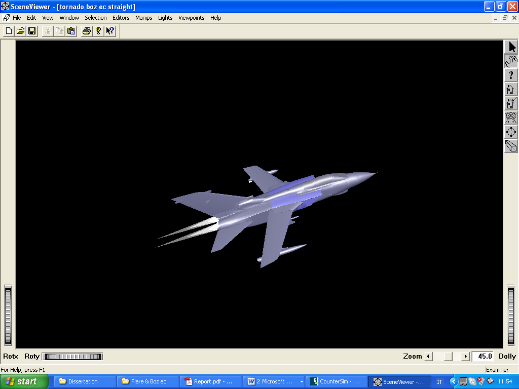
The Aircraft Hierarchy includes the countermeasure (CM) controller that controls the launching of the decoys and the manoeuvres of the aircraft, the Launcher and the Launch Tube from which the flares are deployed. The launch tube contains the flares, which are fired according to the CM controller set up. The launch tube has been rotated 40 degrees down in the elevation plane in order to guarantee a safe separation of the flare from the aircraft.
3 threat model
The type of missile modelled is a second generation MANPAD with a frequency modulated (FM) con-scan seeker. The Missile Hierarchy is shown in Figure 2.
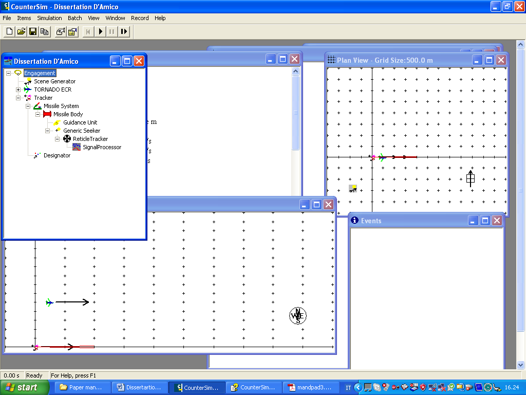
Unfortunately most of the parameters necessary for the simulation of real missiles of this type are not available in open source literature. Consequently, values for these parameters were chosen on the basis of common sense and the functioning of a working simulation. Other generic parameters of the missile body have been taken from open source literature [5]. This process has yielded the parameters listed below:
Body parameters:
Diameter = 70 mm
Total mass = 9.6 kg
Latax limit = 25g
Drag coefficient = 0.3
Natural Frequency = 5 Hz
Damping factor = 0.7
Boost time = 0.5s
Sustain time = 2s
Seeker parameters:
Waveband limit = 3–5 μm
Horizontal and Vertical Gimbal rate = 18 deg/s
Field of View = 1.9 deg
CCM parameters [6]
Type = Track angle rate bias
Bias = 1 deg/s
Bias Duration = 500 ms
Trigger = Rise Rate
Rise Rate sensitivity = 20 target-level/s
Results
1 standard flare pw218
The PW218 Mk3 Type 1 flare has been initially tested as the standard decoy countermeasure flare. They have a format of 2×1 inches and are currently used in a number of dispensing sets, including the AN/ALE 40, 45, and 47 series, Terma, Rokar, Matra, TACDS/Add2, and Saab BOZ EC.
The first set of simulations involved the firing of a single PW218 from the dispenser. Figure 3 shows the data points obtained. In the figure the circles represent the engagement range (in km) with the aircraft in the centre of the plot.
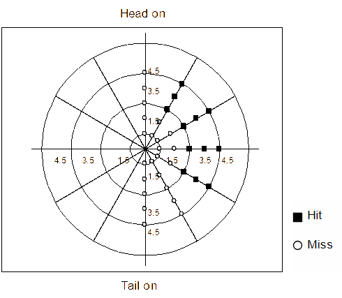
What is immediately clear from Figure 3 is that there are no hits in tail -on and head-on engagements. This can be easily understood by considering that the engagements in these two angles of aspect are characterized by the absence of any lead angle and therefore the CCM of the seeker is disabled. The seeker head is then completely seduced by the flare and will follow it instead of the aircraft plume.
In the crossing engagements the situation is clearly different. The seeker CCM works well in distinguishing the flare from the target due to the relative separation rate and thus these standard countermeasure flares do not give adequate self protection to the aircraft for these engagement aspects.
It is interesting to note the difference between the engagement at 30 degrees and at 150 degrees, that are horizontally symmetric, but with completely different results. In the first case, three hits occur in the range 2.5, 3.5, and 4.5 km; in the second case, there are no hits. The symmetry about the horizontal axis suggests that the seeker has the same field of view (FOV) footprint, however, the different results can be explained by considering the different relative motion between the missile and the target being much more in the forward engagement (30 degrees). Hence, the field of view footprint reduces much quicker in this aspect, causing the flare to exit seeker view more quickly resulting in a hit.
It is also worth noting that no hits occur at the 500m range points. This can be explained by the short engagement time of a Mach 2 missile at such short range; hence the CCM has insufficient time to react.
A second set of simulations was then carried out to assess the effect of two flares fired in a sequence to attempt to ascertain if this could be used as a valid technique against this type of CCM missile. The time delay between the firing of the two flares can have a significant effect on the results, due to the timings used in the missile CCM itself. These effects are summarized in Figures 4 and 5.
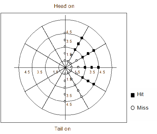

Figure 4 shows the effect of a 50 ms interval between flare firings. Here the level of protection afforded the aircraft is only very slightly better than the single flare case, with only one extra point in the plot (two if the left hand side is considered also) resulting in a miss instead of a hit (range 2.5 km and aspect angle 120 degrees). Figure 5 shows the effect of a 160 ms interval between flare firings. Here the level of protection afforded the aircraft is significantly better with only hits in the 30 degree and 60 degree aspects for ranges of 3.5 and 4.5 km.
Despite this technique of firing the CM flare forward and the greater time interval between the two firings, the aircraft is still not fully protected. This is because of the higher closing velocity of the aircraft and missile in the forward engagements compared to the rear engagements and hence the faster reduction in the FOV footprint and the inability of the flares to remain in the seeker field of view until the CCM is switched off.
2 propelled k7 flare
The propelled K7 flare, as in the case of standard PW218, has a 2×1×8 format; however the K7 has an aerodynamic design and is propelled by means of thrust. These design parameters should clearly enable the K7 to have a reduced separation rate when ejected from the aircraft in a forward direction.
The simulation for a single K7 release can be seen in Figure 6. The results clearly demonstrate the higher effectiveness of the propelled flare in the crossing engagements with no hits having resulted in this type of engagement. There are only two hits that appear in the tail on engagement at ranges 2.5 and 3.5 km. A closer analysis of these two points has determined that the seeker is seduced by the IR decoy and the flare remains in the field of view of the seeker until the closing missile overruns it. Once the missile has overrun the flare, the aircraft is also still in the seeker field of view due to the reduced separation rate and hence the seeker can reacquire the target. This is the disadvantage of the propelled flares in comparison with the standard flare, where their susceptibility due to drag and the effect of gravity pull the missile away from the target.
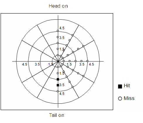
The same results have been obtained for two K7 flares fired in a sequence with varying time intervals between the firings. The reason is that the K7 decoy generates only a small vertical separation rate throughout all its flight profile.
3 evasive manoeuvres
To try and overcome the tail on hits with the K7 flare, the combination of aircraft manoeuvre and flare release has been simulated. Aircraft manoeuvre and flare release is often cited as a typical scenario for avoiding missile impacts [7–9]. Any manoeuvre that requires the missile to turn will impact on the missiles performance typically by the drag induced in creating the lift necessary to perform the missile turn and hence yielding a lower probability of hit. Therefore, in the simulation, two aircraft manoeuvres are considered, a “pull-up” and a “turn” manoeuvre and in each a delay of 0.1s were applied between the release of the flare and the start of the manoeuvre.
Since the flight envelope and then the appropriate value for climb angle and pitch rate is not known for the pull-up manoeuvre, several trials were conducted, considering a range of climb angles between 0 degrees and 30 degrees and a range for pitch rate between 2 degrees/s and 18 degrees/s. Figure 7 describes the results obtained from the engagement at 2.5 km.
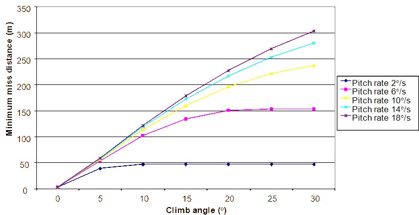
What is clear from looking the graph in Figure 7 is that the aircraft is able to evade the missile, if after releasing the K7 flare it performs a pull-up manoeuvre. The minimum miss distance increases as either the climb angle (for a given pitch rate) or the pitch rate (for a given climb angle). Of course, the limit is given by the manoeuvrability of the aircraft and the acceleration supported by the pilot, which generally cannot exceed 9g. It can therefore be concluded that during a tail-on engagement with a MANPAD, the aircraft is able to break off the line of sight of the missile and hence avoiding the impact by performing a pull-up manoeuvre after having released a K7 propelled flare.
The second manoeuvre modelled was the angle to turn. Reasonable values have been considered for the bank angle and roll rate (60 degrees for the former and 20 degrees/s for the latter). Then the angle to turn has been considered in the range between –170 degrees to +180 degrees in steps of 10 degrees. Figure 8 shows the results obtained from the engagement at 2.5 km.
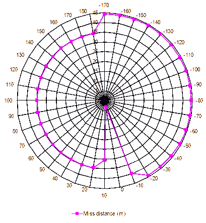
Figure 8 clearly shows that the engagement results in a miss if either the aircraft performs a turn manoeuvre anticlockwise, or clockwise. The value of the miss distance is slightly different due to the asymmetry of the aircraft model, since the dispenser pod has been mounted under the left wing, at a distance of 5m from the aircraft centre of gravity. However, in both cases, because of the inevitable approximations of the simulation and the limitations of the software, it can be said that the miss distance achieved with this manoeuvre (of only approximately 35 to 45m) may not be enough to guarantee the platform self protection.
From the analysis described in Figures 7 and 8, it is clear that the more robust approach for aircraft self protection is to perform the pull-up manoeuvre after having released a K7 countermeasure flare.
Conclusions and future work
This work has investigated the performance of an IR countermeasure dispenser pod, mounted under the wing of a fast jet and compares the effectiveness of two different types of decoy flare, the standard flare (PW218) and the propelled flare (K7), in terms of the miss distance of a second generation MANPAD missile. In order to counter the track angle bias, which may be used in this generation of missile, the technique of firing from the forward dispenser has been exploited. This allows the reduction of the separation rate between the flare and the aircraft and hopefully enables a successful decoy. The modelling and simulation has been conducted using the software “CounterSim” developed by Chemring Countermeasures Ltd. What is clear from the results obtained is a general ineffectiveness of a standard PW218 decoy in seducing this type of IR seeker when dealing with crossing engagements. A self protection of only 48% is obtained with a single flare firing and this can be increased up to 84% in the case of two flares with a time interval of 160 ms between firings. Full protection is not achieved because of the relatively high separation rate that occurs in the forward engagement arc which allows the seeker rate bias to distinguish the flare from the target and push the missile seeker field of view forwards. A more robust solution is represented by the propelled flare, which is capable of sustaining itself in the direction flown by aircraft and therefore is able to reduce the separation rate. The propelled flare is aerodynamically designed and generates thrust. The K7 advanced decoy has been tested in these simulations and the results have demonstrated a larger self protection than that achieved by the standard PW218. In particular, complete platform self protection during crossing engagements has been accomplished. However, because of the nature of the propelled flare, the reduced vertical separation rate that is generated over such a sustained time means that during a tail-on engagement, the missile can over run the flare and reacquire the target. The logical consequence to overcome this problem is to fit the aircraft with both standard and propelled flares, or to perform an evasive manoeuvre after having released the flare. The simulations show that the best manoeuvre is a pull-up manoeuvre when combined with the K7 decoy flare.
Future work will look at the orientation angle of the flare dispenser, different scenarios, different threat missiles, different targets and multiple targets and multiple threats.
References
[1] Jane’s Intelligence Review, January 2009.
[2] Man-Portable Air Defense System (MANPADS) Proliferation, “Understanding the Problem”, www.fas.org.
[3] M.A. Richardson, “The Anatomy of the MANPAD”, SPIE Optics/Photonics in Security & Defence, Florence, Italy, September 2007.
[4] T.B. Hunter, “The Proliferation of MANPADS”, Jane’s, November 2002.
[5] The Worlds Missile Systems, Eighth Edition, August 1988, General Dynamics, Pomona Division.
[6] J. Jackman, M.A. Richardson, P.W.T. Yuen, D.B. James, B. Butters, R. Walmsley, and N. Millwood, “Effect of Pre-emptive Flares on Man-Portable Air-Defence (MANPAD) Systems with a Track Angle Bias Counter-Countermeasure (CCM)”, SPIE European Symposium on Optics/Photonics in Security & Defence, Technologies for Optical Countermeasures VII, Toulouse, September 2010.
[7] R.L. Shaw, Fighter Combat: Tactics and Manoeuvring, Naval Institute Press; 1 December 1985.
[8] Han-Lim Choi, Hyo-Choong Bang, and MinJea Tahk, CO-evolutionary Optimization of Three-dimensional Target Evasive Maneuver Against a Proportionally Guided Missile, Division of Aerospace Engineering, Korea Advanced Institute of Science and Technology.
[9] R.P. Birchenall, M.A. Richardson, B. Butters, and R. Walmsley, “Modelling an IR Man Portable Air Defence System”, Infrared Physics & Technology Journal, Vol. 53, No. 5, September 2010, pp. 372–380.