
Volume 14, Number 1, March 2011
Laboratory Investigation Of Layered Aluminium Mesh For Blast Mitigation Purposes Using A Shock Tube
- * University of Kentucky, Department of Mining Engineering, 230 Mining and Mineral Resources Building, Lexington, KY 40506.
Abstract
A design tool was developed which characterizes the pressure and impulse reduction abilities of an Explosafe Aluminium Mesh over a specific range of scaled distances. This tool was developed by evaluating blast mitigation properties of the mesh through the use of a shock tube. The aluminium mesh reduced pressure and impulse to a greater degree as layers of mesh were increased. Additionally, pressure reduction and impulse reduction come at a design trade-off to one another. As scaled distance increases, impulse reduction increases while pressure reduction decreases. Overall impressive reductions were achieved by such a lightweight and easy-to-handle material, however, these tests began to investigate a lightweight blast mitigation option for the field. A design tool was created utilizing the data from previous arena tests and the shock tube tests discussed in this paper.
Introduction
Research conducted by the manufacturers of an aluminium mesh product called Explosafe (Figure 1) has demonstrated that the product is capable of reducing acceleration peaks, pressure peaks, and deformations resulting from blast shock waves. The aluminium mesh acts via three mechanisms: 1) dividing the shock wave into smaller cells introducing high shear rates therefore inhibiting the propagation of the shock wave [1,2]; 2) absorbing the heat as the wave front passes through the mesh (Explosafe); and 3) reflecting part of the shock wave, reducing the energy of the propagating wave [1]. Typical aluminium mesh applications include insertion into fuel tanks to reduce blast and shock damage from projectiles and fires. Research conducted by the United States Air Force led to specification of this mesh by the Air Force and all Agencies of the Department of Defence for application in fuel tanks (Military Spec). Aside from military applications, current users of Explosafe’s product include petrochemical, automotive, and maritime industries (Explosafe). One objective of this project is to evaluate the mesh for use as blast suppression on the undercarriage of military vehicles, but first, explosive mitigation properties had to be observed and quantified in a controlled environment.
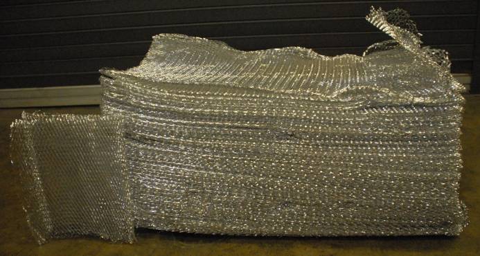
The mesh consisted of 0.004 inches thick aluminium with hexagonal pores 0.06 inches wide. Figure 1 shows a stack of 12 inch by 12 inch mesh samples. These are ideal dimensions and, after the mesh was handled, the mesh’s pore dimensions were unavoidably deformed.
Scaling studies of shock waves
Ma reported a limited study on the shock energy absorption of layered (aluminium) foam cladding in 2006—unfortunately, limited information could be gleaned from this paper and the data was inaccessible [3]. It is assumed that useful literature pertaining to this project exists in the classified work; however, this information was not available to the research team.
There have been multiple studies performed on scaling explosive charges and shock waves [4–8]. The most general and commonly used scaling technique is the Hopkinson scaled distance as described in the ISEE Blasters’ Handbook [9]. Other scaling studies have been performed to account for temperature and pressure differences in the atmosphere surrounding the charge [5,6]. The tests performed for the study described in this paper were performed underground where pressure and temperature were relatively constant [10]. The Hopkinson (cube root) scaling equations were suitable for this application. The units for scaled distance (SD) are ft/lb^0.33 [11].
Work at the University of Kentucky (UK) in 2006 by Grulke and Kitigawa showed that expanded aluminium mesh could reduce blast overpressure. Results from scaled tests with black powder charges have shown that modest thicknesses of layered aluminium mesh reduced shock wave pressures from explosions. At scaled distances near 1.5, overpressure could be reduced by approximately 70% for a 3 cm thick assembly of 20 layers of mesh. Commercial suppliers of aluminium mesh systems have reported good energy absorption in larger scale tests (4 ft by 4 ft unit (“Blastwall”) sections with dynamite), but there is insufficient information to determine what design methods might be used to develop reliable blast mitigation systems.
Previous arena testing by the University of Kentucky Explosives Research Team studying shock wave disruption by the aluminium mesh showed qualitative agreement with these findings [12].
Layered aluminium mesh systems could be a lightweight, low cost method for mitigating blast damage to architectural structures or vehicle panels. A series of tests at different blast and scaled distances provided the grounds for design methods to form a fundamental basis for design rubrics.
Method for assessing blast mitigation
This paper discusses the use of a shock tube to characterize the performance of the aluminium mesh when subjected to blast loadings. This paper builds upon the findings from previous arena theatre tests performed by this research team [12].
To determine the characteristics of the mesh to longer positive phase duration shock waves, a shock tube was constructed. The shock tube is able to replicate large arena test shock waves by detonating a small amount of explosives at a predetermined distance from the test subject. The shock waves generated have a longer positive phase duration that imparts a larger impulse onto the aluminium mesh. The free field peak overpressures from both the arena and shock tube were similar, 9.2 and 8.2 psi respectively. However, the arena shock wave durations (time period for positive pressure) were around 0.5 ms while the shock tube produced durations of approximately 2.0 ms. Since the impulse of the wave is the integral of the pressure with time, the maximum impulse of the arena shock wave would occur at 0.5 ms, since the negative pressure phase succeeds the positive phase. In contrast, the duration of positive pressure in the shock tube test is ~2.0 ms. The area under this curve would be much greater than that for the arena shock wave, resulting in a much greater impulse.
The study reported in this paper is a more complete analysis of the blast mitigation properties of the aluminium mesh. The testing method and results described in later sections of this paper show the ranges of performance and possible applications for the mesh. This paper covers tests performed in a shock tube to replicate an 1102 pound bomb at scaled distances of 10.1, as well as, “non-1102 lb” tests performed to extend the range of scaled distances evaluated.
Experimental setup
The most basic method of subjecting samples to blast loading is by conducting a full-scale test at a remote range where large amounts of high explosives can be detonated. When testing in this manner samples are offset at varying distances from the explosive charge. This way each test subject experiences a different pressure and impulse. Although realistic results can be produced, this method is not without limitations, such as location, availability, and cost. High demand for full-scale testing, a limited number of sites, and the large amounts of explosives, are contributing factors to substantial costs that can be incurred by each test. The ability of a shock tube to simulate the pressure waveform produced in an arena test can greatly reduce the cost for the testing of blast resistant products [13,14].
In the research described in this paper, a shock tube is a rectangular prism constructed from steel with two open ends. Its dimensions are 8 ft wide by 8 ft high by 120 ft long (Figure 2).The shock tunnel provides a cost-effective means of simulating large-scale explosions while only requiring a fraction of the explosives and space. The shock tube allows for the potential simulation of blasts that would ordinarily require hundreds of pounds of explosive in open arena testing while using orders of magnitude less explosive. This is done by confining and directing the pressure shell down the tunnel while spreading out the pressure-time waveform [10,15].
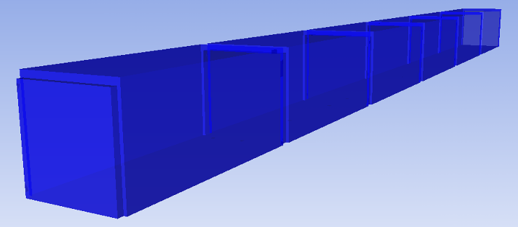
Using this shock tube, blast waves generated by large amounts of explosives (1102 lb SD 10.1) could be simulated. Scaled distances were chosen to provide a broader range of pressure durations for comparison of the mesh performance from previous arena testing [12].
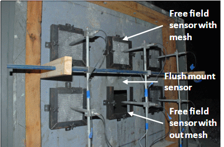
For the tests in the shock tube, six 10-inch square holes were located within a steel plate at the end of the tube. This allowed for five configurations of one foot square mesh to be installed and one with no mesh. All holes had a free-field pressure gauge equidistant from the plate that measured the free-field pressure of the blast. One small hole in the centre of the plate was also created so that a flush mount sensor could record reflected pressures. Figure 3 shows the end of the shock tube with mesh samples and pressure sensors.
The SD 10.1 tests consisted of 22.9 ounces of C-4 hung at 23 ft from the end of the shock tube. The “non 1102 lb” tests included nine tests with charge sizes of 7.05 oz, 14.1 oz, 21.2 oz, and 32 oz of RDX located in the shock tube anywhere from 23 to 69 ft to the free-field sensors. In all tests the charge was hung in the exact centre of the tube by the leg wires of the detonator.
Before testing of aluminium mesh could be conducted in the shock tube, the tube was calibrated so that pressures and waveforms could be predicted. The smaller charges created blast waves in the shock tube similar to those generated by large amounts of explosives, but it was necessary to determine the charge size and standoff required to achieve the target simulation of a 1102 lb bomb. Calibration was achieved by performing multiple tests using the same charge size but varying the distance of the explosives to the measuring point.
The calibration tests were performed for two reasons. The first was to be able to predict the waveform that would be produced at the end of the tube. The second was to confirm that the pressure wave was constant over the entire plate. Results of the calibration tests showed averages and standard deviations of the peak pressure and impulse, in general, were small suggesting that the pressure and impulse distribution across the surface of the steel plate was relatively consistent.
To find the pressure and duration generated by a 1102 lb bomb, the Department of Defense Explosives Safety Board’s Blast Effects Calculator (Version 5.0) was used [11]. A scaled distance of 10.1 was used for the 1102 lb bomb because the pressures expected are within the shock tube's capabilities. By the end of the project, the shock tube was capable of producing reflected pressures of approximately 35 psi with duration of approximately 25 ms and an impulse of approximately 200 psi-ms. The limiting factor was the strength of the shock tube at the location of the charge. With increased strengthening, higher pressures and impulses would be possible. The 1102 lb bomb at SD 10.1 is calculated to produce 23.17 psi reflected pressure with positive phase duration of 27.3 ms [11].
Since the calibration plate recorded reflected pressures, the charge size and standoffs were selected based on reflected pressures. Through calibration the shock tube demonstrated an effective simulation of the 1102 lb bomb at 24.59 psi and duration of 25.94 ms.
The reflected pressure requirements were recreated in the shock tube to achieve the 1102 lb SD 10.1 blast. Then the free-field pressure from this recreation was compared to the expected value from the Blast Effects Calculator of 9.27 PSI. Although the pressures showed good comparisons between the blast calculator and the measured values, the duration of the free-field waves was measured to be substantially less than durations from reflected measurements in the shock tube. Since the free-field measurements had such a short duration that was not in agreement with BEC, testing the mesh in a reflected pressure scenario with a solid backing could be useful to determine the effects of even longer duration waves. This would be a more realistic recreation of potential real world applications of the mesh and would allow for the evaluation of the mesh’s ability to reduce reflected pressure on a solid surface. However, this analysis was not in the scope of this paper.
Results
The “non 1102 lb” data set included nine tests with charge sizes of 7.05 oz, 14.1 oz, 21.2 oz, and 32 oz of RDX located in the shock tube anywhere from 23 ft to 69 ft to the free-field sensors. Five of these nine tests were performed with 7.05 ounces of RDX with ten and 20 layers of mesh. The 1102 pound bomb at SD 10.1 simulation data set consists of ten tests. Tests in the shock tube produced higher pressures with a longer positive phase duration than the arena test experiments [12]. After analysis of the data, comparisons were made to the previous arena tests.
Explosive events created by different charge sizes produce different waveforms. Because of this difference, the “non-1102 lb” data set was subdivided on a test by test basis. Instead of averaging each respective set of pressures (no mesh, 5 layers, 10 layers, 20 layers), the pressure and percentage reduction were calculated for each test and then averaged including standard deviation. The first subdivsion of tests analyzed included all nine tests that ranged from 7.05 to 32 ounces of RDX located in the shock tube anywhere from 23 ft to 69 ft to the free field sensors (Table 1). The second subdivision used the five identical tests (7.05 ounces RDX at 35 ft) within the data set mentioned directly above (Table 2). Analysis of these two data sets give comparisons of pressure reduction of the aluminium mesh when subjected to either different waveforms or the same, repeated, waveform.
These tests were placed together in calculations even though they had many different test waveforms. Their inclusion is to show that no matter what test was performed, some level of pressure reduction was observed.
The next series of tests performed was to simulate an 1102 lb bomb at scaled distance 10.1. Ten tests were performed using identical charge weights at an identical distance from the sensors. From the Blast Effects Calculator, a 1102 lb bomb at a SD 10.1 should produce a 9.27 psi free field pressure, a 23.17 reflected pressure, and have positive phase duration of 27.3 ms.
The cumulative frequency curves were created for the test series. The cumulative frequency plots are a statistical tool and they are indicative of the reproducibility of each particular test configuration. Steeper curves represent more consistent data. These curves also allow for a visual representation of pressure and impulse reduction without looking at individual waveforms. Cumulative frequency curves provided a better visual representation of pressure and impulse reduction than examination of individual waveforms. The locations of the curves on the graph are indicative of pressure and impulse reduction with the addition of mesh layers. Curves for pressure and impulse can be found in Figures 4 and 5 respectively. The figures show a clear reduction in pressure and impulse as mesh layers increase. These scaled distance 10.1 simulations begin to show that the aluminium mesh is less effective at reducing peak pressure at higher scaled distances but more effective at reducing impulse at those same higher scaled distances. More research should be performed on a wider range of scaled distances to completely characterize this behaviour.
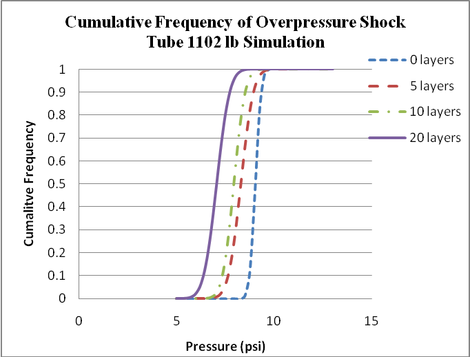
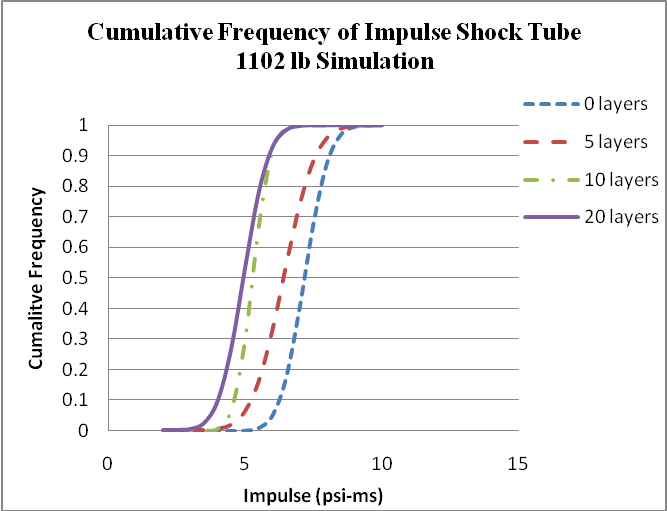
A summary of the results from the ten tests can be seen in Table 3. Between the Table 3 and the cumulative frequency charts, a solid conclusion can be drawn that the mesh is effective at mitigating both peak pressure and impulse for a 1102 lb SD 10.1 blast.
Further investigation into the 1102 lb simulation data set was performed by analyzing the pressure and percentage reduction on a test by test basis. Table 3 shows the average of the pressures for each respective mesh layer and the calculated reductions. Table 4 shows the calculated pressure reduction from each mesh configuration and the average of the values with the standard deviation range. The reduction percentages are in close agreement whichever way the reduction was calculated.
| Table 1. All “non 1102 lb” simulation. | ||
|---|---|---|
| Mesh | Average Pressure Reduction (psi) | Average Percentage Reduction |
| 5 | 0.885 ± 0.492 | 12.29% ± 7.56% |
| 10 | 0.823 ± 0.7215 | 11.66% ± 6.91% |
| 20 | 1.442 ± 0.936 | 22.28% ± 5.72% |
(± standard deviation)
| Table 2. 7.05 oz set statistics. | ||
|---|---|---|
| Mesh | Average Pressure Reduction (psi) | Average Percentage Reduction |
| 10 | 0.439 ± 0.336 | 10.15% ± 7.67% |
| 20 | 0.856 ± 0.231 | 19.87% ± 5.26% |
(± standard deviation)
| Table 3. Peak pressure and impulse reduction 1102 lb SD 10.1. | ||||
|---|---|---|---|---|
| Mesh Layers | Average Pressure (psi) | Average Impulse (psi-ms) | Average Pressure Reduction | Average Impulse Reduction |
| 0 | 9.034 ± 0.251 | 7.165 ± 0.751 | X | X |
| 5 | 8.292 ± 0.530 | 6.403 ± 0.958 | 8.20% | 10.63% |
| 10 | 7.934 ± 0.472 | 5.271 ± 0.535 | 12.17% | 26.44% |
| 20 | 7.054 ± 0.540 | 4.938 ± 0.742 | 21.92% | 31.09% |
(± standard deviation)
| Table 4. Shock tube additional statistics 1102 lb simulation. | ||
|---|---|---|
| Mesh Layers | Average Pressure Reduction (psi) | Average Percentage Reduction |
| 5 | 0.724 ± 0.556 | 8.51% ± 6.15% |
| 10 | 1.162 ± 0.506 | 12.62% ± 5.86% |
| 20 | 1.980 ± 0.648 | 22.54% ± 6.89% |
(± standard deviation)
The pressure front times of arrival in the 1102 lb simulation at SD 10.1 tests was further investigated. The time zero for these events was when the pressure front triggered a flush mount sensor positioned approximately one foot closer to the event than the free field sensors. Had the mesh not affected the pressure front’s advance, the times of arrivals at the free field sensors would have been the same. This was found not to be the case. The sensor positioned without any mesh in front of it constantly experienced the pressure front first where as the times of arrival for the other sensors was dependent upon the amount of mesh in front of it. As more mesh was placed in front of the sensor, the more delayed was the time of arrival. This delay however was sub millisecond in nature.
This suggests that the mesh either slows the pressure front down by robbing it of some energy, or simply delays it by forcing it to take a longer path. This also shows that the shock tube provides a consistent method for creating waveforms that meet the mesh at the same time.
It is evident that the aluminium mesh consistently reduces the peak pressure and impulse of the 1102 lb SD 10.1 simulated blast. The average free field pressure with no mesh was within 3.5% of the expected value (from Blast Effects Calculator) and the reflected pressure was nearly 25% over the expected value (also from BEC) at 29.723 psi.
Statistically, the shock tube tests were much more repeatable than the previously performed arena tests [12]. The general trends of pressure reduction are consistent throughout both types of test series suggesting that even with more sizeable error in the arena test data, quality conclusions can be drawn.
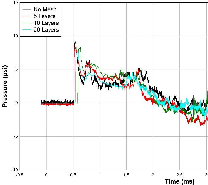
Figure 6 shows the positive phase of the waveforms from a typical 1102 lb SD 10.1 simulation experiment. For each different configuration of mesh, the pressure reduces respectively. The aluminium mesh clips the peak pressure of the waveform and then slightly reduces the positive phase duration resulting yielding a smaller impulse. In this particular test the impulse reduction between no mesh and 20 layers was 19%.
Discussion
- Interpretation of Data
After analysis of the data, the aluminium mesh product has proven promise for reducing the pressure blast effects from high explosives. Overall, 129 mesh sample configurations were tested in the arena tests, and 95 mesh sample configurations were tested in the shock tube. The data shows that in all scaled distance and charge size configurations, 20 layers of aluminium mesh reduced the peak pressure by over 20%. Even five layers of mesh consistently reduce peak pressure by almost 10%. Impulse reduction was not as consistent. Impulse reductions were experienced in the larger scaled distance, but not in the smaller scaled distances.
The trend that is most dominant is that pressure reduction goes up as layers of mesh is increased, closely followed by the trend that pressure reduction goes down as scaled distance goes up. This suggests that longer waveforms may not allow for pressure reduction through the mesh as easily as shorter waveforms like those in smaller scaled distance experiments. Since charge size is also a factor in wave duration, more tests with differing charge sizes would be beneficial as well.
In addition the trend for average impulse reduction is that higher scaled distances allow for greater impulse reduction. This suggests a design trade-off, the basis of a design tool discussed later in this section.
| Table 5. Repeatability summary of shock tube tests. | ||
|---|---|---|
| Layers | Non 1102 lb Tests | 1102 lb SD 10.1 Simulation |
| 5 | 12.29% ± 7.56% | 8.51% ± 6.15% |
| 10 | 11.66% ± 6.91% | 12.62% ± 5.86% |
| 20 | 22.28% ± 5.72% | 22.54% ± 6.89% |
It is believed that energy absorption at the larger scaled distances may have come in the form of transferring blast energy into movement of the mesh; however, more investigation of this theory is necessary before adequate discussion can proceed. When the time scale of a few milliseconds is considered it is likely that the mesh would not be able to react with motion quickly enough to transfer this energy. An alternative hypothesis is that the mesh acts porously and tends to slow the advance of the blast wave as it progresses through the mesh. Analysis of the high-speed video could yield correlations between movement and resulting blast wave duration.
The clipping of short duration waves suggests that energy from the blast wave may not be absorbed, but rather pushed to longer duration by restricting the flow and particle velocity. It is evident that more of a trend in impulse reduction exists in the larger scaled distances. This is somewhat counterintuitive when considering the mechanics of a blast wave. Generally larger scaled distance equates to longer duration and thus higher impulse. Perhaps this is the fundamental reason for better performance of the mesh at larger scaled distance. If more impulse is available, more can be utilized as energy for movement of the mesh. Further investigation of the mesh is called for to determine the mechanics of this phenomenon. Since all of the mesh tests were performed in a free field format that allowed for the mesh to move away from the blast, a comparative study of reflected pressure measurements with mesh covering solid surfaces could provide insight to impulse reduction.
- Shock Tube Test Repeatability
Similar to the arena tests, the waveforms are visually similar for each test in the shock tube series. Statistically the results are much better for the shock tube tests. Table 5 shows the pressure reduction percentages for the shock tube data. The series was separated into two categories. The categories are those that simulated the 1102 lb scaled distance 10.1 blast and those that did not. The reduction percentages for the 20 layer mesh configurations are on the order of ±6% which is statistically accurate. The nature of the shock tube test drives this statistical accuracy as the mesh was a greater distance from the charge, and directional effects were nullified by the fact that all mesh samples tested were in the same plane perpendicular to the charge. The percentages also agree with the previous tests discussed in the introduction of this paper. It is believed that longer duration waveforms are not reduced as efficiently as shorter duration waves by the mesh.
Design tools
The data collected for this project shows that a design trade off exists between pressure reduction and impulse reduction. At the higher scaled distances investigated in this study, the mesh reduces impulse quite effectively, while at the lower scaled distances the mesh shows little or no ability to reduce impulse. Conversely, pressure is reduced more effectively by the mesh at lower scaled distances. Over the range of scaled distances tested here, Figure 7 can be used to determine what level of pressure and impulse reduction can be expected across the range of layer configurations tested. The figure was created from the data collected in both the arena and shock tube tests.
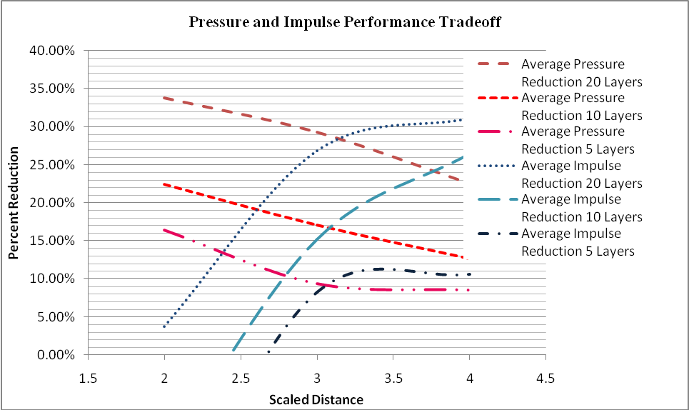
Several specific conclusions can be drawn from Figure 7. First, the aluminium mesh reduced pressure and impulse increasingly as layers of mesh were increased. Also, a design trade-off exists between pressure reduction and impulse reduction. Frequency/duration of pressure time curve affects the performance of the mesh. From the graph, at scaled distance 7.6 and 20 layers of mesh, the pressure and impulse reduction both are approximately 28%. This is quite an impressive reduction for such a lightweight and easy to handle material. The aluminium mesh is not very robust, and thus operationally, methods will need to be developed prior to implementation on active vehicles. The performance trade-offs shown in Figure 7 apply only to the range of overpressures and impulses studied in these test. Conditions that are well outside the experimental range could cause changes in blast mitigation mechanisms that were not observed here.
The design tool presented in Figure 7 does not account for differences in charge size, but rather averages performance across the charge sizes used for the test series in this project. Since pressure duration is believed to be an integral variable concerning the performance of the mesh, further study of single scaled distances with varying charge sizes could provide more definitive tools based on the actual pressure duration rather than on scaled distance which only scales pressure. The tool does however allow for a starting point when deciding on possible applications for the aluminium mesh products. The data collected in this project suggests that further investigation could provide solutions for military vehicles exposed to blast attacks.
Testing with solid objects behind the mesh to simulate vehicle, structure, or personnel protection are needed to provide further information for the application of the mesh. Blast mitigation differences should be evaluated for stand-alone panels as tested for this project and panels backed by solid objects such as a structure.
Summary and conclusions
Aluminium mesh has previously shown the ability to mitigate blast effects in the form of reducing free-field pressure and reducing impulse created by small charges (<2 oz) [12]. The shock tube testing results showed that the mesh is more efficient at pressure reduction at lower scaled distances while it more effectively reduces impulse at higher scaled distances. However, the effect of charge size has not been completely characterized, and it is uncertain whether this relationship would continue as the range of charge sizes was broadened. In general, keeping charge size constant, as scaled distance increases longer durations would result; likewise, larger charge sizes would also produce longer duration wave forms when the scaled distance is held constant.
Fundamental mechanisms of the performance of the mesh have been identified. It is theorized that the mesh’s porosity could be a fundamental mechanism by which the mesh performs. Analysis of the shock front’s time of arrival showed a slowing or delaying effect on the shock front as it passed through the mesh. Further investigation would be required to determine which phenomenon dominates performance. Should it be shown that the mesh doesn’t slow the shock front, but rather extends its path and delays it; this amount of delay could be used to determine pressure and impulse reduction similar to the delay experienced by distance. The attenuation of blast waves through a distance of air is well documented, and could provide additional design tools if delay time could be correlated to a distance and thus free field pressure or impulse reduction. It is also theorized that the mesh’s porosity has a “cellularizing” effect on the shockwave which mitigates the shock front.
The aluminium mesh reduced pressure and impulse increasingly as layers of mesh were increased. A design trade-off exists between pressure reduction and impulse reduction and this relationship was developed into a design tool (Figure 7). The performance of the mesh was a function of the pressure time curves’ frequencies and durations. Impressive reductions were achieved for such a lightweight and easy to handle material. However, the aluminium mesh is not very robust, and thus operationally, methods will need to be developed prior to field implementation.
References
[1] Y. Andreopoulos, S. Xanthos, and K. Subramaniam, “Moving Shocks Through Metallic Grids: Their Interaction and Potential for Blast Wave Mitigation”, Shock Waves, Springer-Verlag, March 2007.
[2] R.S. Wakeland and R.M. Keolian, “Measurement of Resistance of Individual Square-Mesh Screens to Oscillating Flow at Low and Intermediate Reynolds Numbers”, Journal of Fluids Engineering, Vol. 125, September, 2003.
[3] G.W. Ma, and Z.Q. Ye, Energy Absorption Capacity of Layered Foam Cladding, Department of Civil and Environmental Engineering, Nanyang Technological University, Singapore, Springer-Verlag, 2006.
[4] W.E. Baker, Explosions in Air, University of Texas Press, 1973.
[5] J.M. Dewey, “Air Velocity in Blast Waves from TNT Explosions”, Proceedings of the Royal Society, Ser. A 279(1378), pp. 366–385, 1964.
[6] H. Kleine, J.M. Dewey, K. Ohashi, T. Mizukaki, and K. Takayama, “Studies of the TNT Equivalence of Silver Azide Charges”, Shock Waves, Vol. 13, No. 2, pp. 123–138, 2003.
[7] P.W. Cooper, Explosives Engineering, Wiley-VHC Inc., NewYork, 1996.
[8] G.F. Kinney, and K.J. Graham, Explosive Shocks in Air, Springer, New York, 1985.
[9] ISEE, Blasters Handbook 17th Edition, International Society of Explosives Engineers, Cleveland, Ohio, 1998.
[10] J. Hoffman, B. Lusk, and K. Perry, “Investigations of Shock Tunnel Dynamics and Energy Realization”, Blasting and Fragmentation, Vol. 3, No. 3, pp. 207–226, ISEE, Cleveland, OH, 2009.
[11] M.M. Swisdak Jr, DDESB Blast Effects Computer, US Department of Defence, Washington DC, 2001.
[12] B. Lusk, K. Perry, and J. Hoffman, “Laboratory Investigation of Layered Aluminium Mesh for Blast Mitigation Purposes Using an Arena Setup”, Journal of Battlefield Technology, Vol. 13, No. 2, July 2010, pp. 1–12.
[13] B. Lusk, “Large Arena Test Simulator Using Small High Explosive Charges”, Proceedings of the Thirty-second Conference on Explosives and Blasting Technique, Orlando, FL, International Society of Explosives Engineers, Cleveland, Ohio, 2006.
[14] B. Lusk, K. Perry, and S. Lusk, “Predictability of a High Explosives Shock Tube for Testing Blast Resistant Windows”, Blasting and Fragmentation, Vol. 4, No 2, pp. 75–89, ISEE, Cleveland, OH, 2010.
[15] Q. Qu, “The Evolution of a Detonation Wave in a Variable Cross-Sectional Chamber”, Shock Waves, Springer-Verlag, 2008.