
Volume 13, Number 3, November 2010
Impulse Density Of 155 Mm Projectile As A Function Of Distance
- 1 MBDA—TDW Schrobenhausen, Hagenauer Forst 27, 86529, Schrobenhausen, Germany.
Abstract
155 mm projectiles are detonated in a test arena with steel momentum plates of 30×50×2cm3 with 23.55 kg weight, positioned 1.25m above the ground where their achieved velocities are measured by the displacement distance on the ground. Although the impulse density results show a large scatter, they can be roughly described as exponential equations of the scaled displacements.
Introduction
The impulse density values of confined charges as a function of distance is not well known, nor are many results published in the open literature. In [1], the author has already presented the impulse density of cylindrically cased charges with 60 mm charge diameter in mild steel tubes of 2.5 mm, 5 mm, and 10 mm wall thickness, with charge outside diameters of 65 mm, 70 mm, and 80 mm [1]. In that work, the impulse densities of the blast wave and fragments were measured at four distances of 1m, 1.5m, 2m, and 3m. The impulse plates were 500 mm high, 600 mm wide, and 15 mm thick with an individual weight of 35.3 kg. But the total weight of the sled with the plate was 51.5 kg.
The height of the plates was large enough to cover the main part of the cylindrically expending fragments along the charge length of 290 mm, and therefore to cover the total impulse of blast and fragments in the elevation direction of +/–6.6° for 1 m distance, +/–4° for 1.5m distance, +/–3° for 2m, and finally +/–2° at 3m distance. The impulse has driven the sleds to velocities that were measured with wire positioning sensors or displacement transducers and a normal video camera. The achieved results could be relatively well described by the following equation for impulse density, ID:
where µ is the ratio of the steel casing to the high explosive charge (µ has an approximate value of 3, as a mean value for a 155 mm projectile), R is the distance from the charge, and W is the weight of the charge.
With µ = 3 and W = 6.8 kg the constant is then 0.273 for the equation predicting ID for the 155 mm projectile DM 21 as a function of the distance R, so that the equation becomes:
The straight line in the logarithmic diagram of Figure 1 of the reflected scaled impulse densities between the scaled distances Z of 0.4 to 3 can be described with the exponential equation [2]:
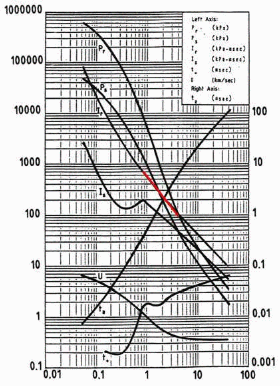
where Z is the scaled distance, which is R divided by the cube root of the charge weight (Z = R/W1/3). This is valid for a TNT sphere of 1 kg weight in the open air.
A charge weight of 6.8 kg increases the constant by the cube root, which is 1.9 and therefore:
Cylindrical charges have impulse density values in the radial directions in the near distance that are larger than those for spherical charges by a factor of about 2 to 3 times [3]. This leads then to the following equations:
Drawing these equations in Figure 2 then the spherical charge with 6.8 kg charge weight is represented by the lowest curve, the equation for the cylindrical charge with the factor of 2 is represented by the middle line and the factor of 3 is the top line derived from the author’s own tests [1]. The goal of the following tests was to check if this equation also predicts the impulse density values of the 155 mm high explosive projectiles DM 21.
![Calculated impulse densities as a function of scaled distance: 6.8 kg spherical HE [2], 6.8 kg cylindrical HE by a factor of 2 [2], 6.8 kg cylindrical HE by a factor of 3 [2], and for 6.8 kg HE and µ = 3 for metal and HE ratio [3].](/journals/journal-of-battlefield-technology/volume-13/issue-03/assets/13-3-2-held/figures/figure02.gif)
Test setup
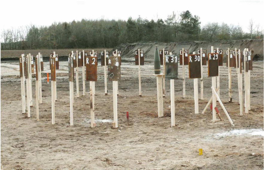
The bottom of the 155 mm projectile DM 21 was arranged vertically above the ground, so that the height of its centre of gravity was 1.25m. The 155 mm high explosive projectile DM 21 is filled with 6.8 kg TNT and has a total weight of 45 kg (Figure 3). Momentum plates were arranged in radial directions in two arcs, beginning at 1.5m and increasing in 0.25m steps up to 5m distance in two symmetric branches each with 14 momentum plates (Figure 4).
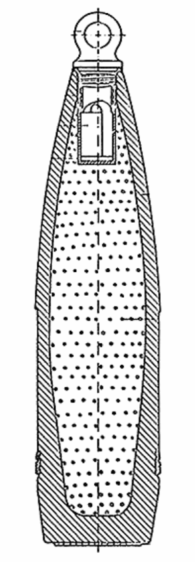
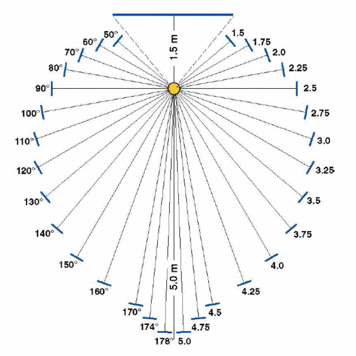
For measuring the impulse density, caused by the blast wave and fragment loads, a larger momentum plate was selected than had been used in previous tests. For this test campaign plates of 30 cm width and 50 cm height with 2 cm thickness were chosen. Each plate had a weight of 23.55 kg that meant that it could be just managed manually. These plates were stood on a wooden stick of 1m height above the ground. On this was fixed a thin second smaller wooden stick with a bent nail on top to hold the plate in place in the vertical position. This small wooden stick was facing the charge.
The Figure 5 shows the 155 mm projectile in front and behind the plates with the holding device. A photograph of the test arena is presented in Figure 6.
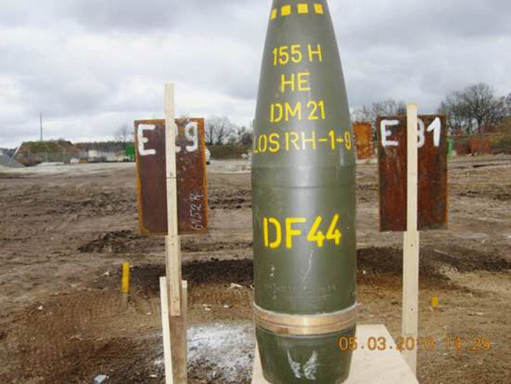
The impulse is defined as the product of mass and velocity. The mass is given by the momentum of the steel plates with 23.55 kg weight. A good indication of the transferred velocities can be given by the displacement distances of the plates on the first impact on the ground. Necessary for this procedure is a nearly horizontal push in the starting phase.
If the plates fall vertically down without turning, then the dropping height is 1m and the falling time is 0.45s. If the plates are turning and falling down with their length on the ground then the falling height is 1.25m and therefore the falling time 0.50s.
The falling time is given by the following equation:
where g is the gravitational constant.
This is not a very precise diagnostic method to achieve the initial velocities. But it is at least a positive method to measure the velocities of 28 plates in sometimes rough environment over a larger cross section area.
The impulse density ID is given by the quotient of impulse I and cross section area A, which is 1,500 cm2 in this case.
Summarizing the above equation, the impulse density can be given for the two dropping cases in the following way:
Test results
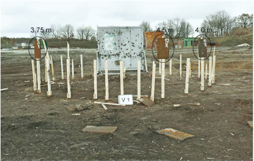
Figure 7 shows the test arena after the detonation of the 155 mm high explosive projectile. In Figure 8 are shown the impulse density values for falling from 1 m (higher values) and 1.25 m height (lower values) for each individual distance for both arms. The large scatter of data is surprising and it is really astonishing that three plates are still standing in place after the firing. This means the distribution of the impulse around the charge is strongly structured.
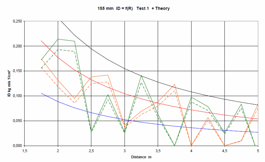
The predicting equations are added to the experimentally achieved results. The three curves represent the lower, the middle and the top values (Figure 8). In this test arena three 155 mm projectiles were detonated and the impulse densities measured. The values of these six measurements—two for each firing—are summarized in Figure 9 which shows a trend although, as mentioned before, with a lot of scatter of the data.
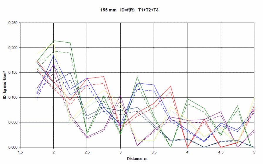
The impulse density values as a function of distance are strongly scattered for the detonation of 155 mm high explosive projectile DM 21. These results can be roughly described with exponential equations:
- derived from earlier tests with confined cylindrical charges, taking the µ-factor and the charge weight into account, or
- from diagrams of reflected scaled impulse densities of spherical TNT charges as functions of scaled distances, also taking into account the charge weight and the cylindrical shape of the charge geometry by the factors 2 and 3.
Acknowledgement
Many thanks for the support and the interest on these tests by Klaus Hüsing of the Military Test Centre Meppen and to Ludger Niemeyer for the great technical support on all these tests.
References
[1] M. Held and G.E.B. Tan, “Radial Blast Loads of Confined Cylindrical Charges”, 11th International Symposium “Interaction der Wirkung von Munition mit Bauwerken”, Mannheim, Germany, 2003.
[2] P.D. Smith and J.G. Hetherington, Blast and Ballistic Loading of Structures, Laxton’s, Figure 3.10, p. 38, 1994.
[3] M. Held, “Blast Contour of Cylindrical Charges with Different Length to Diameter Ratios”, 11th International Symposium “Interaction der Wirkung von Munition mit Bauwerken”, Mannheim, Germany, 2003.