
Volume 13, Number 3, November 2010
The Effect Of Low-Angle Yaw On The Armour Penetration Of Light Armour-Piercing Projectiles
- 1 Cranfield Defence and Security, DA-CMT, Shrivenham,Wilts, UK.
Abstract
The performance of 7.62×54r BS32 armour-piercing incendiary (API) projectiles against ceramic-faced armour is investigated in trials for yawed impacts. Controlled yaw of the projectile was induced by chamfering the rear of the projectile, producing strong asymmetric lift forces on the tail of the round during the intermediate ballistics phase. High-speed video recorded yaw in two orthogonal planes immediately before impact. Projectile yaw varied in a sinusoidal manner at approximately 3.5m wavelength with a maximum of 8–14° at approximately 10m from the muzzle. Logistic regression was used to determine the penetration probability curve and V50 ballistic limit velocity which was found to be 735 ms–1 for the un-yawed projectiles but only 685 ms–1 for the yawed projectiles.
Introduction
It is generally recognised that for maximum armour penetration a projectile should impact with little or no yaw so that kinetic energy density is maximised. However there is some evidence of anomalous effects at small angles of obliquity [1] which might imply an effect at small angles of yaw. This would be an important effect as small yaw angles are difficult to detect in routine tests. In this work the performance of 7.62×54r B32 armour-piercing incendiary (API) projectiles against ceramic-faced armour was determined for slightly yawed (>5°) with normal impacts (<5°). This projectile was chosen as it is a standard test round defined in NATO STANAG 4569 [2]. To test the effect of yaw the method developed by Coburn [3] was used to induce a small yaw angle in the projectiles. Trials were then conducted with a target placed at 10m from the muzzle. High-speed video was used to record the projectile yaw in two orthogonal planes immediately before impact. Firings were then conducted with both yawed and un-yawed projectiles against a silicon-carbide-faced aramid composite target and the ballistic limit was determined for both cases.
Ammuniton
The 7.62×54R B32 is a boat-tailed API projectile with a hardened steel core, surrounded by a lead sheath and encased within a gilding metal-coated steel jacket. The magnesium-based incendiary composition is positioned both in the nose cavity and in a gilding metal-coated steel cup in the base of the projectile.
Figure 1 shows a complete projectile and components from a sectioned projectile (left to right: whole projectile, half of jacket, steel core above incendiary cup, half of jacket).
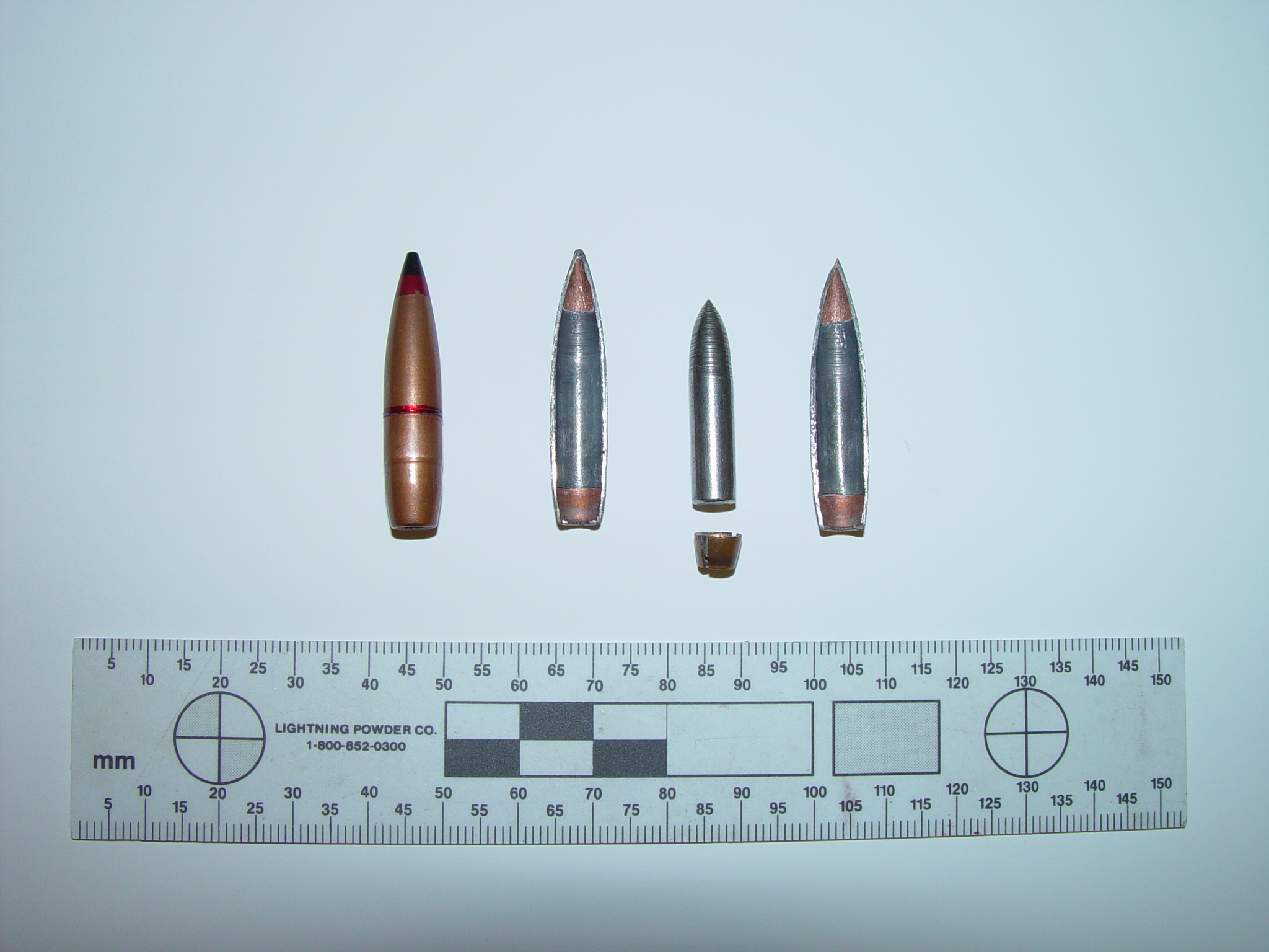
Three projectiles from batches of 7.62×54R ammunition, manufactured by two factories (identified from headstamp) from 1952–1983 were dismantled to confirm projectile construction and to allow measurement and hardness testing of the steel cores. Vickers hardness on each core was determined using a micro-hardness tester (INDENTEC HWDM-7) with a load of 2 kg. Average dimensions, masses, and Hv values are listed in Table 2.
| Projectile length | 37.8 mm |
|---|---|
| Projectile diameter | 7.9 mm |
| Projectile mass | 10.4 grams |
| Propellant mass | 3 grams |
| Core length | 28.3 mm |
| Core diameter | 6.2 mm |
| Core mass | 5.4 grams |
| Core material | Steel |
| Core hardness | 870–970 HV |
| Headstamp | Length (mm) | Diameter (mm) | Mass (grams) | Micro Vickers Hardness Hv | |
|---|---|---|---|---|---|
| Factory | Year | ||||
| 21 | 1952 | 28.29 | 6.17 | 5.33 | 971 |
| 21 | 1957 | 28.26 | 6.16 | 5.33 | 938 |
| 17 | 1981 | 28.38 | 6.16 | 5.41 | 913 |
| 17 | 1983 | 28.32 | 6.13 | 5.37 | 872 |
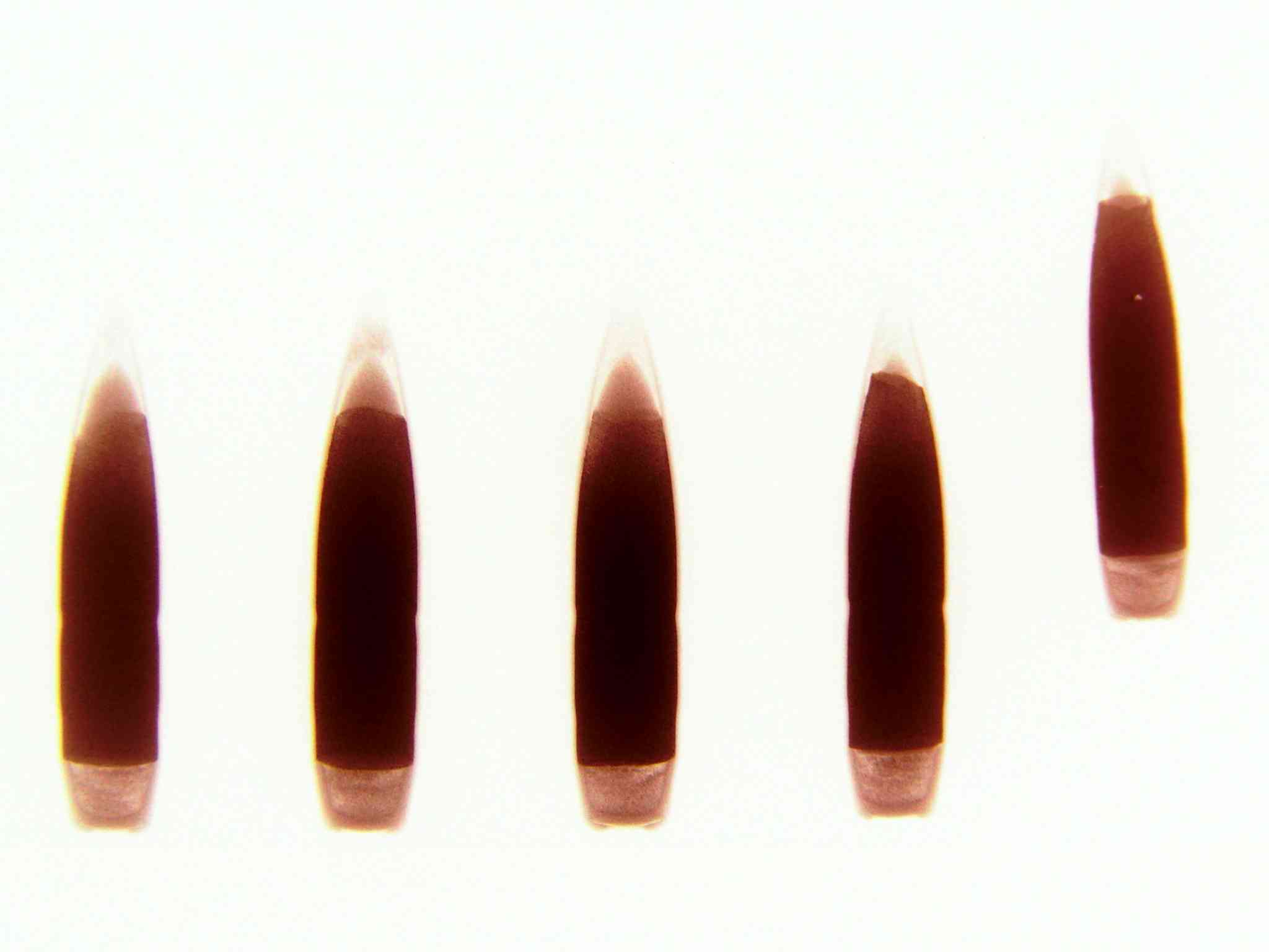
Radiographs were taken of all 69 projectiles in the trial to assess consistency of production within a single batch and across a number of batches (with different factory and date information on the headstamp). Figure 2 shows the radiograph of the projectiles from Factory 21 ammunition used for all yawed test firings (PANTAK Industrial Radiograph equipment and KODAK Industrex C Film settings: energy 120 kV, current 3 mA, exposure time 2 minutes). The length of the lead sheath in all batches of B32-API tested was found to vary, this feature combined with the lack of concentricity of the lead sheaths may be sufficient to alter significantly the centre of gravity position (along and away from the projectile axis) and potentially affect the level of stability in flight. The variability in the turnover can easily be seen in Figure 2, as can the inconsistent incendiary density in the rear cup.
Inducing yaw
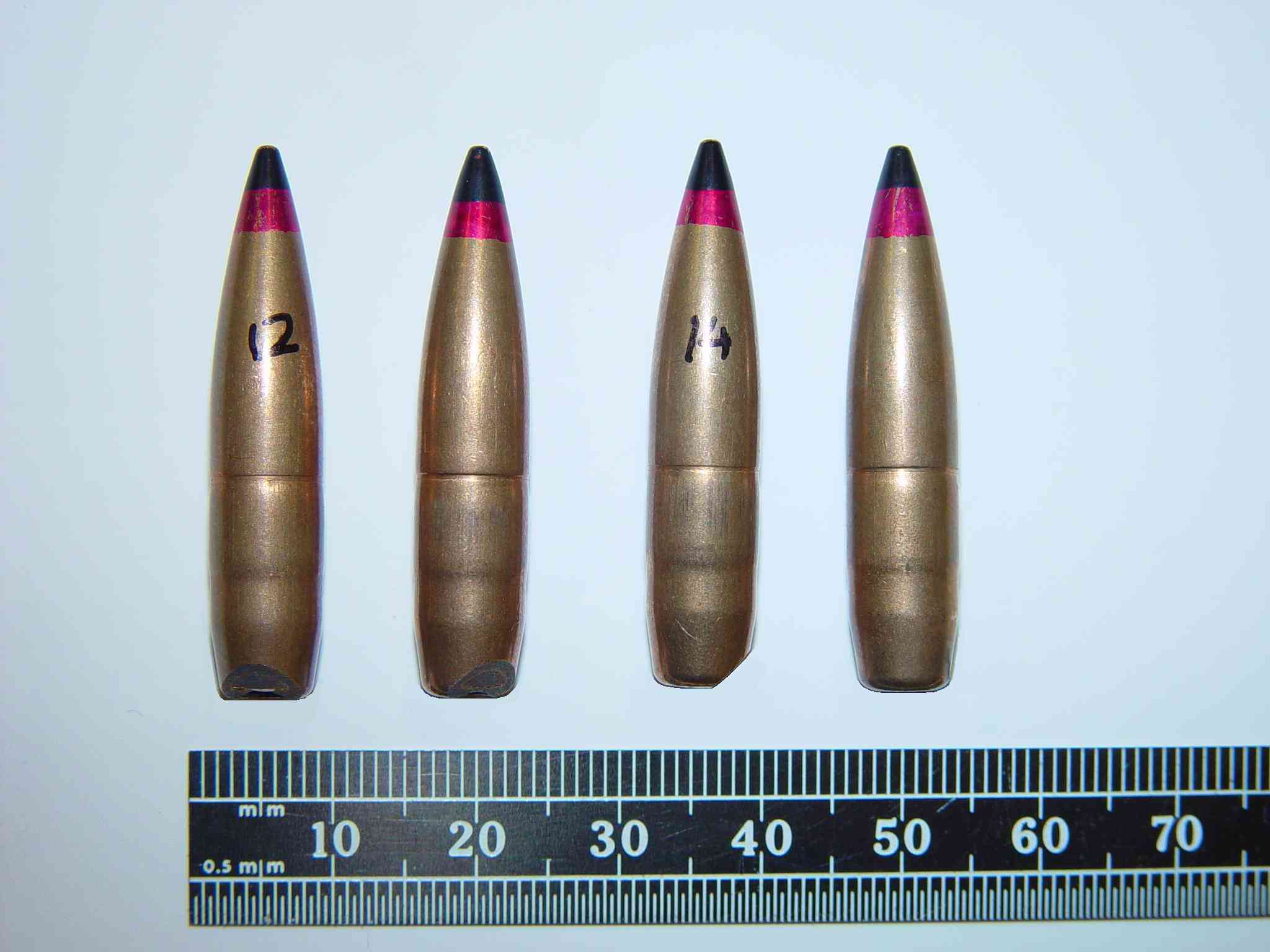
Of the potential methods for inducing yaw in the order of 5–15°, chamfering the base of the round had been shown by Coburn [3] to achieve the majority of these requirements, with the exception of the amount of yaw induced. The induced yaw from a 45° chamfer across the whole diameter of the projectile’s base (as shown in the left-hand image of Figure 3) was shown to be approximately 30° for a 7.62-mm ball round fired at a velocity of 800 ms–1. So the 45° chamfer was limited to a cut width of 3 mm from the outer edge of the jacket as shown in Figure 3. The reduction in projectile mass was less than 1.5% of the original projectile mass.
Test firings
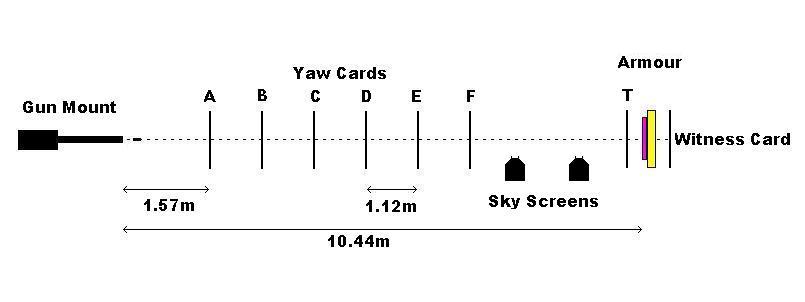
A proof mount with a gun barrel length of 720 mm and a twist length of 240 mm (1 in 9.45 in) was used to fire the projectiles. Velocity was measured by two MS Instruments Optical Detectors with yaw cards placed in the path of the projectile throughout the range as shown in Figure 4.
Measurement of yaw
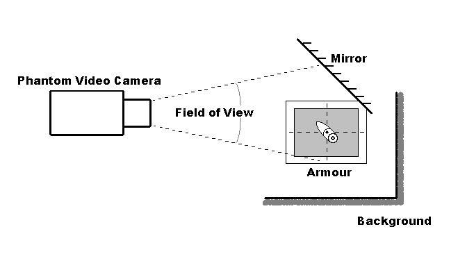
All test firings were recorded using a Phantom high-speed video camera at a frame rate of 4,700 pictures per second and exposure time of 2 µs, In order to detect yaw in orthogonal planes, a mirror was erected at an angle of 45° to the plane of the camera, within the field of view of the camera, thus capturing a side view (pitch) and top view (yaw) of the projectile prior to impact with the target, Figure 5.
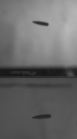
The projectile tip and centre of the base of the projectile were used as measurement points for evaluating the pitch and yaw angles from individual frames of video files. The top image of the projectile in Figure 6 is seen as the ‘top view’ in the mirror, and the bottom image is the ‘side view’. The projectile is travelling from right to left and yawing with its tip right 11.5° (Figure 6a ) and down 6° (Figure 6b) relative to the direction of flight.
The overall yaw of the projectile is:
where:
α’ is the yaw in one orthogonal plane, and
αꞌꞌ is the yaw is the second orthogonal plane.
So taking αꞌ= 6° and αꞌꞌ = 11.5° the overall yaw of this projectile was calculated to be 12.9°.
A total of 16 chamfered projectiles were fired during the experimental investigation 15 of which yawed by more than 5°. In addition to the high speed video recording, yaw cards were placed at measured intervals (A–F shown in Figure 4) in the path of the projectile to record projectile yaw angle (overall yaw rather than pitch and yaw components), monitor the yaw rate / period and to confirm the round was at least neutrally stable during flight. An additional yaw card was placed 100 mm from the front face of the ceramic armour to confirm overall projectile yaw at impact (position T shown in Figure 4). The witness holes left in the yaw cards provided a means of determining the amount of yaw, as well as the relative tip orientation about the line of flight, as it rotated due to precession.
Witness holes on the yaw cards and recorded video showed that all rounds were neutrally stable and were not tumbling. Chamfered rounds were fired at velocities in the range 680–820 ms–1, with the only round failing to yaw being recorded at a velocity of 811 ms–1. The angles of yaw recorded by the yaw cards are summarised in Table 3.
| Positions | A | B | C | D | E | F | T |
|---|---|---|---|---|---|---|---|
| Distance from muzzle (m) | 1.57 | 2.69 | 3.81 | 4.93 | 6.05 | 7.17 | 10.34 |
| Velocity (ms–1) | Yaw Angle | ||||||
| 685 | 21 | 12 | ≤5 | 20 | 11 | 7 | ≤5 |
| 690 | 17 | 13 | ≤5 | 15 | 14 | ≤5 | 11 |
| 693 | 14 | 10 | ≤5 | 13 | 13 | ≤5 | 10 |
| 697 | 12 | 10 | ≤5 | 7 | 12 | 7 | 11 |
| 702 | 14 | 12 | ≤5 | 12 | 13 | ≤5 | 11 |
| 706 | 8 | 7 | ≤5 | ≤5 | 8 | 7 | 7 |
| 715 | 10 | 10 | ≤5 | ≤5 | 7 | 7 | 7 |
| 716 | 12 | 10 | ≤5 | 7 | 12 | ≤5 | 10 |
| 717 | 14 | 10 | ≤5 | 12 | 12 | ≤5 | 8 |
| 725 | 20 | 12 | ≤5 | 18 | 12 | ≤5 | ≤5 |
| 728 | 12 | 11 | ≤5 | 8 | 12 | ≤5 | 10 |
| 810 | 8 | 7 | ≤5 | ≤5 | 7 | ≤5 | 7 |
| 810 | 10 | 8 | ≤5 | 7 | 10 | ≤5 | – |
| 811 | ≤5 | ≤5 | ≤5 | ≤5 | ≤5 | ≤5 | – |
| 818 | 13 | 11 | ≤5 | 7 | ≤5 | 12 | 10 |
| 829 | 14 | 10 | ≤5 | 12 | 12 | ≤5 | 8 |
Ballistic test results
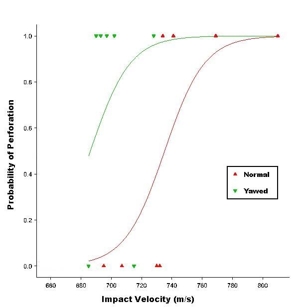
The V50 ballistic limit was determined for unmodified and un-yawed rounds against the ceramic-faced targets. The ballistic limit velocity of the B32-API against the candidate ceramic faced composite armour was calculated to be 735.5 ms–1, being the average of six shots, three perforations and three stops. The date for an individual test is shown in Table 4. Seven of the chamfered rounds were fired against the ceramic faced composite targets at velocities below the V50, Table 4. The highlighted figure represents a shot where the velocity was calculated based on the distance travelled by the projectile between successive frames of the recorded video. The results show that five of six of the yawed rounds were able to perforate the armour system at velocities below the V50 for normal impact. The slowest chamfered round (685 ms–1) which failed to perforate the target may not reflect the ‘ballistic limit’ for yawed impact as it was shown that this particular round, whilst yawing early in its flight, impacted the target with minimal yaw, and can therefore be assessed as a non yawed impact. Additional non-yawed impacts at velocities in the range 695–707 ms–1 showed the armours’ ability to stop the B32-API round, establishing that the reduced velocity perforations were not happening as the result of the shatter gap phenomena.
Due to the small sample size of yawed impact test results it is difficult to establish the statistical significance of the perforations at velocities below the V50 for normal impacts. Figure 7 shows a logistic regression plot of the normal and yawed impact results. The full binomial distribution curve for the normal impact V50 test firings corresponds well to the calculated V50 of 735.5 ms–1. The partial curve fitted to the yawed impact results is based on the limited samples available, and shows that a ballistic limit velocity for the yawed impact results would fall below that for normal impacts. As the data points to assess the statistical significance of the yawed impact curve are limited it can only be indicative, however it shows that the V50 for yawed impact may be as much as 50 ms–1 below the normal impact V50.
| Velocity Ms–1 | Areal density of armour kg/m2 | Perforated / stop | Yaw ≤50 at impact |
|---|---|---|---|
| 769 | 19.39 | Perforated | No |
| 741 | 19.38 | Perforated | No |
| 734 | 19.41 | Perforated | No |
| 730 | 19.40 | stop | No |
| 732 | 19.37 | stop | No |
| 707 | 19.44 | stop | No |
| V50 = 735.5ms–1 | |||
| 728 | 19.06 | Perforated | 10 |
| 715 | 19.24 | Stop | 7 |
| 702 | 19.37 | Perforated | 11 |
| 697 | 19.46 | Perforated | 11 |
| 693 | 19.66 | Perforated | 10 |
| 690 | 19.27 | Perforated | 11 |
| 685 | 19.89 | Stop |
The relatively high occurrence of yaw greater than 5° in the unmodified B32-API rounds is most likely as a result of effects during intermediate ballistics, possibly due to variations of turnover affecting the symmetry of reverse flow of propellant gas as the projectile leaves the muzzle. The level of consistency of the reverse gas flow in each batch is also likely to vary with the shape of the rear edge of the boat tail
Whilst there is noticeable variation in the length and symmetry of the lead sheath around the hardened core, this is unlikely to have been a significant cause of instability (and hence yaw) when firing B32-API projectiles from the test gun.
Conclusions
The expectation that maximum penetration is achieved with an ideal normal impact does not always hold true, particularly in the case of the B32-API round against a silicon carbide / KM2 Kevlar armour system. Small angles of yaw have been shown to enhance the penetrative ability of the armour piercing round. The mechanism by which yawed rounds show improved penetration is not known and will require further work to quantify the effect.
References
[1] P.J. Hazell, M.J. Iremonger, P.C. Barton, and J.P.F. Broos, “Anomalous Target Failure at Small Angles of Obliquity”, Proceedings of the 21st International Symposium on Ballistics, Adelaide, Australia, 19–23 April 2004.
[2] STANAG 4569, Protection Levels for Occupants of Logistic and Light Armoured Vehicles, NATO Standardization Agency, 2004.
[3] S.J. Coburn, Enhancing Ballistic Protection by Inducing Yaw, Royal Military College of Science, Shrivenham, United Kingdom, 1996.