
Volume 13, Number 2, July 2010
New Electro-Optic Simulator Design Concepts For Serviceability Checks Of Laser Seekers And Laser-Warning Sensors
- 1 Laser Science and Technology Center (LASTEC), Defence Research and Development Organization (DRDO), Metcalfe House, Delhi-54, India.
- 2 Department of Applied Sciences, Amity University, Noida, India.
Abstract
Precision-guided munitions (PGM) play a pivotal role in modern warfare. As such it is important to carry out serviceability checks on critical electro-optical systems particularly those incorporated into precision-guided munitions, laser-warning systems and other military electro-optic systems. These test systems provide functionality checks on military electro-optic systems without the need to disassemble the device under test (DUT) or remove it from the platform. This paper presents new design concepts to build portable electro-optic simulators capable of generating battlefield laser threat signatures to carry out on-line functionality checks on laser sensors used in laser-warning systems and laser seekers in laser-guided munitions. These designs offer one or more advantages over similar commercially available devices and designs discussed in the literature. A prototype using the proposed concept was built and comprehensively evaluated by testing a commercial laser-seeker unit. Test results are presented in this paper.
Introduction
Laser seekers and laser warning sensors are two of the most widely used military electro-optic sensor systems [1,2]. A laser warning system is an integral part of any anti-sensor defensive or offensive electro-optic countermeasures (EOCM) system. In both cases, knowledge of the type and precise angle-of-arrival of the laser threat may be used to either trigger a cluster of aerosol/smoke grenades to block the laser radiation from the adversary’s laser designator in the case of defensive operation; or a high-energy laser to neutralize the target sensor in the case of offensive operation. The laser seeker is the heart of the guidance unit used in laser-guided munitions, which primarily include cannon-launched surface-to-surface projectiles and missiles, and airborne laser-guided bombs and missiles. Due to the tactical importance of these two types of laser sensors, there is a need to carry out functionality testing of laser-guided munitions and laser-warning systems at regular intervals [3]. Portable test systems do exist to perform on-line functionality checks on these two types of laser sensors [4,5], but these systems suffer from one or more limitations.
Test systems available commercially and those discussed in literature do not generate laser signatures to test the advanced features of state-of-the-art laser-seeker heads and laser-warning systems. Laser-guided munitions test systems for instance test the laser seeker’s response to the desired and undesired PRF codes one at a time. In the contemporary battlefield scenario where these guided munitions operate in the presence of countermeasures deployed by the adversary, there is a requirement for the test system to be able to generate the laser signatures that a laser-seeker head may be subjected to. The test system should be able to test the seeker’s response to (a) correct PRF codes in the presence of false PRF codes (b) simultaneous presence of a weak and a strong correct PRF code. Also, all test systems are designed for seeker heads operating at 1,064 nm and do not address the requirement of future seeker heads operating at 1,540 nm. Laser-warning systems are also designed to detect and identify multiple laser threats of the same or different types such as those from laser range finders, laser target designators and laser-beam riders. These systems operate at 1,064 nm (laser range finders, laser target designators, and laser-beam riders); 1,540 nm (laser range finders); and 810 nm / 905 nm / 915 nm (semiconductor laser range finders and laser-beam riders). Laser-warning systems are therefore designed to handle one or more of these wavelengths with similar or different intensity levels.
Design concepts discussed in the following paragraphs address all these issues and lead to the development of test systems that can be used to perform on-line functionality testing of both present day laser-seeker heads and laser-warning systems and those likely to be in use in the foreseeable future.
Design concepts—electro-optic simulator concepts for laser seekers
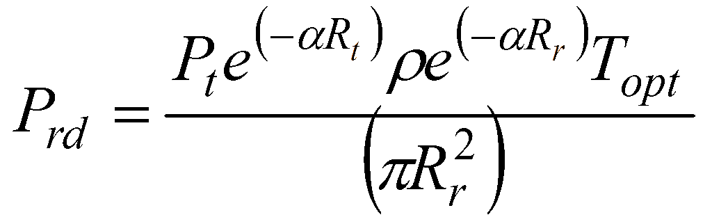
In a typical laser-guided munitions delivery, the seeker head in the guidance unit of the weapon makes use of laser radiation scattered from the target irradiated by a laser target designator. The seeker head generates information on the angular error, which in turn is used to generate command signals needed to guide the weapon to the target [3]. The laser target designator and the seeker head use the same PRF code, and the PRF code compatibility check forms the basis of identification of the desired radiation and hence target. PRF code compatibility is therefore essential to the weapon’s functionality and mission success. All laser-guided munitions delivery systems offer a set of PRF codes to give to the user the option of using any of these codes for a given mission. The test system therefore should be capable of generating user selectable PRF code at the desired wavelength and power density level. The laser radiation power density intercepted by the laser seeker over its operational terminal guidance range is calculated from:
where:
Prd = received power density at the seeker.
Pt = power transmitted by the laser designator.
α = atmospheric attenuation coefficient.
ρ = target reflectivity.
Rt = range between laser designator and target (Designating range).
Rr = range between target and laser seeker (Seeking range).
Topt = transmission of seeker optics.
Equation (1) is valid when the laser beam does not overspill the target, which is true for most of the application scenarios. In cases where the laser beam does overspill the target, the power density is reduced by a factor equal to the ratio of target area to the laser spot area at the target distance.
Signal strength received at the laser seeker for typical laser guided munitions delivery operation varies from 5−10 µW/cm2 (close to the maximum terminal guidance range) to 10−50 mW/cm2 (close to the blind range). These figures can be calculated from (1) for typical values of laser designator peak power and beam divergence, visibility, target reflectivity, atmospheric attenuation, and designating and seeking ranges. Also, the laser seeker sees a beam that overspills it, hence the actual portion intercepted can be treated as collimated. A good test device therefore should generate a collimated beam with a laser spot diameter greater than 75 mm so as to overspill the laser seeker having a front end optics cross-section in the range of 25−50 mm.
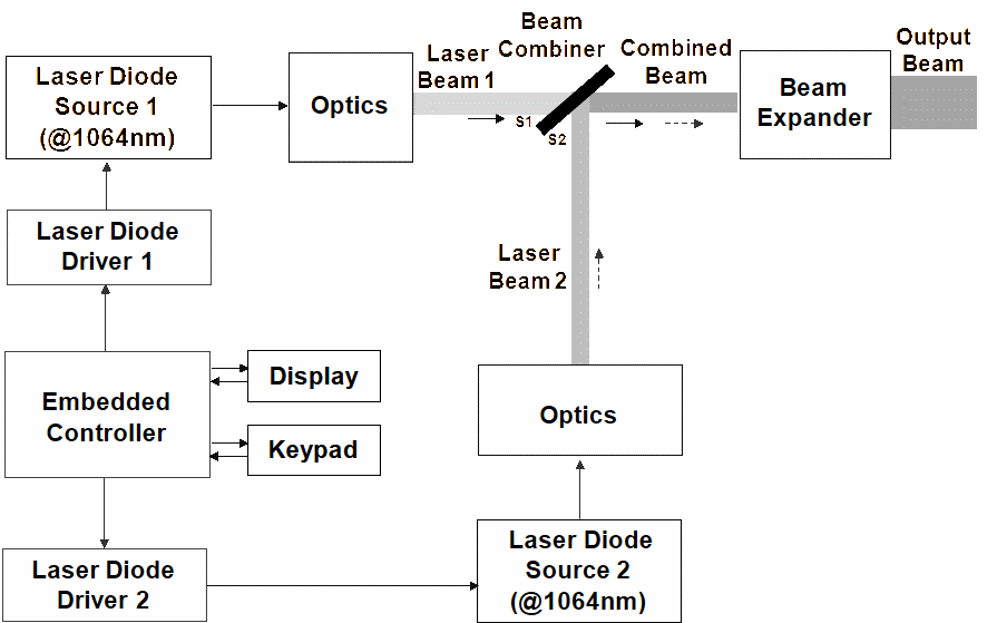
Figure 1 illustrates one possible design that can be used to perform the functionality checks on laser-guided munitions operating at 1,064 nm. The design is configured around a set of two high-bandwidth laser diode sources producing a 1,064 nm continuous wave (CW) output, having the desired power level, line width, and wavelength stability and also an external trigger input for pulsed operation. The bandwidth of the chosen laser diode source is large enough to produce pulsed laser output with the desired pulse width. A 100-MHz bandwidth, for instance, allows generation of a minimum of 10 ns laser pulses from the laser source. The power level at the exit of laser source should be adequate for generating the desired maximum power density level in the expanded laser beam. The other power density level is then generated with the help of a suitable neutral density filter.
Both laser sources provide circular beams. The outputs from the two sources are combined in a beam combiner that has a near 100% transmission coating at 1,064 nm on one side (S1) and near 50% reflective and 50% transmission coating at 1,064 nm on the other (S2). The common beam is expanded through a suitable beam expander to produce the desired laser beam size. Laser sources are driven by respective driver sources as shown, which in turn are driven by the embedded controller. The embedded controller is designed to generate all control and drive signals for the two laser sources for various operational modes. Possible operational modes are that only laser source-1 is ON; only laser source-2 is ON; and both laser source-1 and laser source-2 are ON simultaneously. The embedded controller is also interfaced to a suitable keypad for entering data and a module to display the selected operational mode and other information.
Use of two laser sources allows the user to generate different deployment scenarios where the laser seeker encounters laser radiation of the correct PRF code, the wrong PRF code and both correct and wrong PRF codes simultaneously. The option of using a neutral density filter allows the generation of a strong signal with the correct PRF code in the presence of a weak signal with the wrong PRF code or vice versa. This allows the user to perform the following functionality tests:
a) PRF code compatibility check at maximum and minimum operational ranges.
b) False code rejection test at weak and strong intensity levels.
c) Mixed code test with the correct PRF code laser radiation more dominant than the wrong PRF code laser radiation.
d) Mixed code test with the wrong PRF code laser radiation more dominant than the correct PRF code laser radiation.
These features, which are representative of contemporary laser-guided munitions delivery scenarios, are neither available commercially in any of test systems nor are these addressed in designs proposed in the literature.
If one of the laser sources in Figure 1 is replaced by a 1,540 nm source as shown in Figure 2, the test set-up can be used to test both present day 1,064 nm as well as 1,540 nm laser seekers making the proposed concept more versatile. Surface S2 of the beam combiner in this case has a nearly 100% reflective coating for 1,540 nm and nearly 100% transmissive coating for 1,064 nm. The resulting test device however is not capable of performing the mixed code tests (listed at (c) and (d) in the previous paragraphs).
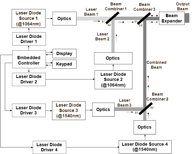
The limitation of the design shown in Figure 2 is overcome in the design shown in Figure 3. The proposed concept is an extension of those outlined earlier in the schematic arrangements of Figures 1 and 2. The design uses four laser diode sources, two of 1,064 nm and two of 1,540 nm, of the types used in the design of Figure 2. There are three beam combiners used in the design. The surface S1 of beam combiner 1 has nearly 100% transmissive coating at 1,064 nm while surface S2 has a nearly 50% reflective and 50% transmissive coating at 1,064 nm. Surface S1 of beam combiner 2 has nearly 100% transmission at 1540 nm while surface S2 has a nearly 50% reflective and 50% transmissive coating at 1,540 nm. Beam combiner 3 has 100% transmission at 1,064 nm for surface S1 and a reflection of 100% at 1,540 nm and 100% transmission at 1,064 nm for surface S2. The embedded controller along with driver circuits drives the four laser sources. This design can be used to perform all tests that the design of Figure 1 is capable of for both 1,064 nm and 1,540 nm laser seekers. In addition, the design is capable of testing the laser seeker for the desired wavelength and correct PRF code in the presence of the desired wavelength at false PRF code simultaneously with an undesired wavelength at correct PRF code and undesired wavelength at an incorrect PRF code.
Design concepts—electro-optic simulator concepts for laser-warning sensors
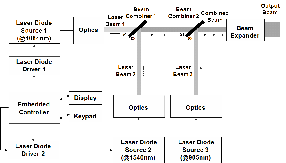
The designs proposed in Figures 2 and 3 can be used to test laser-warning sensors for threats from laser range finders and laser target designators operating at 1,064 nm and 1,540 nm. Laser-warning sensors encounter much higher power levels compared to those intercepted by laser seekers due to direct irradiation in the case of the former and indirect irradiation in the latter. Laser diode sources therefore should be selected accordingly. The design of Figure 3 can be used for testing the capability of the laser sensor to respond to the simultaneous presence of multiple laser threats of different types. However, these set ups do not cater for laser sensor testing against laser-beam rider threats typically operating around 905 nm. Figure 4 shows the arrangement for building a laser-warning sensor test rig capable of simulating laser range finders, laser target designators and laser-beam rider threats individually as well as collectively. The schematic of Figure 4 is self explanatory.
In the designs illustrated in Figures 2 to 4, the beam expander used to produce the desired beam diameter is required to transmit more than one wavelength in some modes. In such cases, for a fixed design, the beam diameter at different wavelengths will be slightly different due to refractive index variations. Since the size of front-end optics of the sensor under test are much smaller than the laser beam, this slight variation in radiation spot size does not affect the performance of the test system.
Prototype hardware
Prototype hardware was built to implement the design of Figure 1. Figure 5 shows the CAD view of the prototype hardware. The prototype hardware was used to evaluate comprehensively the performance of a selected international seeker unit, by performing PRF code compatibility tests, false PRF code rejection tests and mixed PRF code tests. Figure 6 shows the test set-up. In the test set-up, the laser beam axis and the optical axis of the laser seeker unit are co-linear.
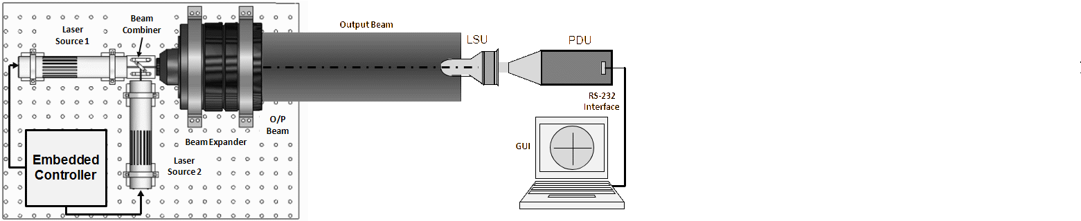
In the case of the PRF code compatibility tests, the laser source-1 (LS-1) is operated at power density settings of 10 µW/cm2 and 1.0 mW/cm2 one at a time and laser source-2 (LS-2) is kept deactivated. Seeker lock-on was observed for ten different correct PRF code settings. The same PRF codes were fed to the laser seeker unit and the test system. Test results are summarized in Table 1. The figures mentioned under PRF code columns in Table 1 to Table 4 indicate the time interval between two successive laser pulses in milliseconds (ms).
False code rejection test is performed in a manner similar to PRF code compatibility test. The PRF codes set in laser source-1 (LS-1) in this case are the false codes and the lock-on status is observed on the display. Test results are summarized in Table 2.
In the mixed code test, the correct code is fed in to either of the two laser sources and the wrong code is fed in to the other laser source. The test is performed in two steps. In the first step, laser source-1 and laser source-2 are operated at power density settings of 10 µW/cm2 and 1.0 mW/cm2 respectively and lock-on status is observed for ten different settings of PRF codes. In the second step, laser source-1 and laser source-2 are operated at power density settings of 1.0 mW/cm2 and 10 µW/cm2 respectively, and the test is repeated. Test results are summarized in Table 3 and Table 4.
| Power Density = 1 mW/cm2 | Power Density = 10 µW/cm2 | ||||||
|---|---|---|---|---|---|---|---|
| S. No. | PRF code on LSU | PRF code on LS-1 | Lock-on status | S. No. | PRF code on LSU | PRF code on LS-1 | Lock-on status |
| 1. | 50.000 | 50.000 | Locked | 1. | 50.000 | 50.000 | Locked |
| 2. | 80.000 | 80.000 | Locked | 2. | 80.000 | 80.000 | Locked |
| 3. | 100.000 | 100.000 | Locked | 3. | 100.000 | 100.000 | Locked |
| 4. | 105.042 | 105.042 | Locked | 4. | 105.042 | 105.042 | Locked |
| 5. | 105.984 | 105.984 | Locked | 5. | 105.984 | 105.984 | Locked |
| 6. | 106.044 | 106.044 | Locked | 6. | 106.044 | 106.044 | Locked |
| 7. | 106.188 | 106.188 | Locked | 7. | 106.188 | 106.188 | Locked |
| 8. | 106.398 | 106.398 | Locked | 8. | 106.398 | 106.398 | Locked |
| 9. | 106.598 | 106.598 | Locked | 9. | 106.598 | 106.598 | Locked |
| 10. | 107.008 | 107.008 | Locked | 10. | 107.008 | 107.008 | Locked |
| Power Density = 1 mW/cm2 | Power Density = 10 µW/cm2 | ||||||
|---|---|---|---|---|---|---|---|
| S. No. | PRF code on LSU | PRF code on LS-1 | Lock-on status | S. No. | PRF code on LSU | PRF code on LS-1 | Lock-on status |
| 1. | 50.000 | 80.000 | Unlocked | 1. | 50.000 | 80.000 | Unlocked |
| 2. | 80.000 | 50.000 | Unlocked | 2. | 80.000 | 50.000 | Unlocked |
| 3. | 100.000 | 105.042 | Unlocked | 3. | 100.000 | 105.042 | Unlocked |
| 4. | 105.042 | 100.000 | Unlocked | 4. | 105.042 | 100.000 | Unlocked |
| 5. | 106.188 | 105.984 | Unlocked | 5. | 106.188 | 105.984 | Unlocked |
| 6. | 105.984 | 106.188 | Unlocked | 6. | 105.984 | 106.188 | Unlocked |
| 7. | 106.398 | 105.188 | Unlocked | 7. | 106.398 | 105.188 | Unlocked |
| 8. | 106.598 | 106.398 | Unlocked | 8. | 106.598 | 106.398 | Unlocked |
| 9. | 106.610 | 107.008 | Unlocked | 9. | 106.610 | 107.008 | Unlocked |
| 10. | 107.008 | 105.984 | Unlocked | 10. | 107.008 | 105.984 | Unlocked |
| S. No. | PRF code on LSU | PRF code on LS-1 | PRF code on LS-2 | Lock-on status LS-1 and LS-2 Activated | Lock-on status LS-1 OFF and LS-2 Activated |
|---|---|---|---|---|---|
| 1. | 50.000 | 50.000 | 80.000 | Locked | Unlocked |
| 2. | 80.000 | 50.000 | 80.000 | Locked | Locked |
| 3. | 100.000 | 105.042 | 100.000 | Locked | Locked |
| 4. | 105.042 | 105.042 | 106.188 | Locked | Unlocked |
| 5. | 106.188 | 106.188 | 107.008 | Locked | Unlocked |
| 6. | 106.398 | 106.398 | 106.598 | Locked | Unlocked |
| 7. | 106.598 | 106.598 | 107.008 | Locked | Unlocked |
| 8. | 107.008 | 107.008 | 105.042 | Locked | Unlocked |
| 9. | 105.984 | 105.984 | 106.598 | Locked | Unlocked |
| 10. | 106.610 | 106.610 | 106.803 | Locked | Unlocked |
| S. No. | PRF code on LSU | PRF code on LS-1 | PRF code on LS-2 | Lock-on status LS-1 and LS-2 Activated | Lock-on status LS-1 OFF and LS-2 Activated |
|---|---|---|---|---|---|
| 1. | 50.000 | 50.000 | 80.000 | Locked | Unlocked |
| 2. | 80.000 | 50.000 | 80.000 | Locked | Locked |
| 3. | 100.000 | 105.042 | 100.000 | Locked | Locked |
| 4. | 105.042 | 105.042 | 106.188 | Locked | Unlocked |
| 5. | 106.188 | 106.188 | 107.008 | Locked | Unlocked |
| 6. | 106.398 | 106.398 | 106.598 | Locked | Unlocked |
| 7. | 106.598 | 106.598 | 107.008 | Locked | Unlocked |
| 8. | 107.008 | 107.008 | 105.042 | Locked | Unlocked |
| 9. | 105.984 | 105.984 | 106.598 | Locked | Unlocked |
| 10. | 106.610 | 106.610 | 106.803 | Locked | Unlocked |
Conclusion
This paper discusses design concepts to build electro-optic simulators to test the seeker heads of laser-guided munitions and laser warning sensors without the need to disassemble them or even remove them from the platform. Designs are presented for laser seeker testers to generate laser target signatures as seen by the seeker head under realistic battlefield conditions allowing the user to check on their advanced features such as false code rejection, immunity to countermeasures, and ability to perform in low signal-to-noise conditions. Designs are also discussed for laser sensor testing to generate different spectral signatures to test the response of the sensor to the individual or simultaneous presence of common battlefield laser threats such as those from laser range finders, laser target designators and laser-beam riders. These designs allow for the development of portable electro-optic test systems that can be used to perform comprehensive on-line functionality checks of laser-guided munitions and laser-warning sensors. The proposed designs address the limitations of commercially available devices and designs reported in the literature for similar applications.
References
[1] E. Thibeault, J. Fortin, and G. Pelletier, “Testing and Development Methods for Laser Decoys”, Journal of Battlefield Technology, Vol. 9, No. 3, November 2006.
[2] J. Mei, Laser Warning Receiver, National Air Intelligence Center, Wright-Patterson AFB OH, August 1996.
[3] K. Chrzanowski, “Testing of Military Optoelectronic Systems”, Optoelectronics Review, Vol. 9, No. 4, 2001.
[4] W.J. West, “Developmental Testing of a Laser-Guided Bomb Simulation”, AIAA 2008-1629, US Air Force T&E, 5-7 February 2008, Los Angeles, California.
[5] E.W. Kopala, W.R. Lamboley, and G.L. Spencer, “A Target Simulator for Evaluating Laser Guided Missile Performance During Closed Loop Homing Operations”, Electro-Optics/Laser Conference and Exposition, USA, 25-27 October 1977.