
Volume 13, Number 2, July 2010
Design Issues And Results For High-Data-Rate Mobile Tactical Networks
- 1 Lockheed Martin Australia Electronic Systems, 45 Third Ave., Mawson Lakes, SA 5095.
Abstract
The development of technologies that allow interoperable radios on a number of networked nodes for tactical scenarios has seen much interest in recent years. In particular, the Joint Tactical Radio System (JTRS) is one project aimed at designing interoperable tactical data links for a number of scenarios involving United States and coalition forces. The JTRS project was motivated by a number of factors concerning extant tactical data links. These factors include a lack of interoperability and the proprietary nature of the radios required, as well as the inability of such links to allow high-rate ad hoc networked communications in a highly mobile environment. It has been suggested that existing commercial off-the-shelf equipment could perhaps be used for tactical networking. Subsequently, in a previous paper by the author, preliminary results were presented for an example tactical networking scenario. In that paper, it was assumed that high-gain antennas could be used in such a way that they always provided maximum gain, irrespective of the locations of each node, and the types of antenna gain patterns that could be achieved with such antennas. Additionally, size, weight and power (SWAP) constraints were not considered. In this paper, SWAP constraints are considered in determining an example set of transmit power and antenna types to investigate the effects of such practical constraints on the data rates that could be achieved. Also, a single ground-reflector model is used for the wireless channel, instead of the line-of-sight only model assumed in the previous work. Results obtained by simulation of an adaptive orthogonal frequency division multiplexing scheme are provided for a range of possible asset separation distances. These results highlight both the effect of distance-dependent signal attenuation, and also antenna pointing mismatch. Such effects would need to be jointly considered when designing a high-rate tactical data network.
Introduction
It has been established that extant tactical data links are unable to support scenarios commonly encountered in modern warfare (for example [7,11]). Moreover, many of the radios for the implementation of such links are proprietary in nature, leading to a lack of interoperability for networked scenarios. This has motivated initiatives such as Joint Tactical Radio System (JTRS), which adopts software defined radios (SDRs) for achieving greater performance and interoperability for use in network-centric warfare. Yet interoperability requires not only the fielding of new, more-capable SDRs, but also support for retrofit efforts, which are often heavily cost-constrained, and would benefit from less costly commercial-off-the-shelf based solutions.
In [2], the concept of developing a truly open standard for tactical military networked communications was suggested. At Lockheed Martin Australia Electronic Systems (LMAES), in conjunction with defence and academia partners, application and modification of commercial technologies for tactical military networks is being studied. In doing so, it is prudent to investigate a number of issues that would affect the performance of such networks in practice.
In [13], upper bounds on physical layer throughput were provided, based on a set of assumed transmit powers and antenna gains for an example small tactical network. Based on an assumed waveform it was also demonstrated by simulation that such high-data-rate networks would be feasible, albeit in somewhat benign channel conditions. At LMAES, efforts have continued primarily at the physical layer, whilst additional work for the project has been continued at higher layers by project partners. This paper is focused on the results of the continued physical layer investigations. In contrast to the work presented in [13], the current work takes into account practical issues such as antenna gain patterns and the associated loss in gain due to fixed antenna orientations on some assets. Moreover, estimated size, weight and power (SWAP) constraints have been included when determining transmit powers and antenna gains.
This paper is organised as follows. The following section provides a description of the example tactical scenario. Section III provides details on the assumed physical layer waveform and Section IV provides details on the medium access control scheme. Numerical results obtained via physical layer simulation for each point-to-point link are then presented in the fifth section. The implications of these results are subsequently discussed, taking into consideration the assumed medium access approach. The paper concludes with an overview of ongoing work, and suggestions for further investigation.
Tactical scenario description
The scenario used for establishing performance metrics in this paper consists of the following four basic node types:
- A manned forward element (MFE).
- An unmanned aerial vehicle (UAV).
- A strike asset (SA), such as a jet fighter.
- An aerial command and control (C2) node.
The responsibilities of these node types are summarised in Table 1, and are based on those described in [3].
Data rate requirements
Based on the responsibilities outlined in Table 1, and the nominal data rates provided in [3], a table of uplink and downlink data rates required for the scenario is given in [4], and repeated in Table 2. Here it was assumed that the data rate required for text-based command, control and status (C2S) information is assumed to be negligible; for voice, it is up to 48 kbps; for 30 fps low-resolution video, up to 2 Mbps; for 10 fps high-resolution video, up to 5 Mbps; the C2S for the UAV is approximately 512 kbps.
| Node Type | Responsibilities |
|---|---|
| MFE | Initial observation and designation of a target Launch and control the UAV Follow the target whilst maintaining voice communications with the SA and C2 nodes |
| UAV | Provide high-resolution video to all other nodes at a rate of 10 frames per second (fps) Send status information to the controlling MFE node |
| SA | Prosecute the target and provide low-resolution video to the C2 node at a rate of 30 fps Maintain voice communications with the MFE and C2 nodes |
| C2 | Provide text-based command, control and status information to all other nodes except the UAV Act as a gateway to operational and strategic communications systems Maintain voice communications with the MFE and SA nodes |
| C2 | MFE | SA | UAV | Total Downlink | |
|---|---|---|---|---|---|
| C2 | 0 | 48 | 2048 | 5000 | 7096 |
| MFE | 48 | 0 | 48 | 5512 | 5608 |
| SA | 48 | 48 | 0 | 5000 | 5096 |
| UAV | 0 | 512 | 0 | 0 | 512 |
| Total Uplink | 96 | 608 | 2096 | 15512 |
| Node Type | Air-to-ground level (m) | Speed (km/h) |
|---|---|---|
| MFE | 5 | 15 |
| UAV | 300 | 111 |
| SA | 300 | 1200 |
| C2 | 10000 | 278 |
Scenario model
The numerical results presented later in this paper are based on Monte-Carlo simulations in which results are recorded for point-to-point links between each asset type for a range of link distances. Each asset is assumed to have the location/mobility parameters as described in Table 3.
It should be noted that the specific locations of each asset in the horizontal plane are not considered, since in this work the channel is modelled as a ground-reflector plus a line-of-sight (LOS) path, and thus only the assets’ air-to-ground levels and the inter-asset distances will affect the results. It should also be noted that with the assumed channel model, and since the ground-reflection is assumed to be specular (and hence not time-dependent on a small time-scale), the vehicular speeds do not have an appreciable effect on the simulation results, but instead were used when considering the specific parameters for the physical layer waveform.
Physical-layer communications model
For obtaining the numerical results presented later in this paper, the following assumptions have been made with regard to the physical layer:
- All point-to-point links in the network are assumed to have LOS with a single specular ground-reflector, as would be feasible when using moderately directional antennas in an open area.
- The bandwidth available is assumed to be 35 MHz, with ideal Nyquist filtering (no excess bandwidth).
- The system noise temperature at each receiver is assumed to be 800 K, which corresponds to a system noise figure of 5.75 dB.
- Additional losses of 3 dB are included.
- The carrier frequency is assumed to be 5 GHz for example purposes only; interference with other communications in this band is not considered.
- Orthogonal frequency division multiplexing (OFDM) with adaptive modulation is utilised, similar to the position adaptive transmission scheme described in [12], and having the same frame structure. Synchronisation is assumed to be ideal, and common phase error estimation is not performed (phase noise is assumed to be negligible). Specific parameters of the OFDM scheme and the frame structure are based on the mobility parameters described in Table 3.
- Error correction coding is assumed to cope with pre-decoder bit error rates below 9.5%, as would be the case with the coding scheme assumed in [12,13].
- Channel estimation is performed using the same method described in [12], and used to rotate and scale the received symbols on each data carrying OFDM sub-carrier.
Antennas and transmit powers
In deciding on suitable example antennas and transmit powers (see Table 4) to use for each node, assumed size, weight, and power (SWAP) constraints have been taken into consideration. Specifically, the C2 is assumed to be the largest asset, with least restrictions on antenna size and transmit power. The SA, which would likely need to have a stealthy profile, is limited to a low gain, fixed position omni-directional (in azimuth) antenna, but due to its moderate size, it is assumed to still be capable of supporting a reasonably high transmit power. The MFE is assumed to be a truck or jeep with limited available power, though still sizeable enough to support a more customised, higher gain antenna. This is assumed to a pencil-beam (or torch-like) pattern, which is sufficiently steerable (perhaps if achieved via a phased array) to always point at the asset it is communicating with. The C2 antenna is assumed to have the same shape (though smaller beamwidth) beam pattern, and is also assumed to have similar steering capabilities. The UAV, which would the smallest and least capable (in terms of transmit power and signal processing) is assigned a low transmit power, and is assumed to have no capability for beam-steering, and is thus chosen to have a single, fixed, low-gain, omni-directional (in azimuth) antenna.
It should be noted that the antenna types and gains provided in Table 4 are for example purposes only, to demonstrate how the different gains and patterns would affect a tactical network in which they were able to be used. In practice, different antenna gains and patterns may be mandated, and the results in this paper could be used in ascertaining the types of effects that such mandates would place on particular instances of a tactical network.
Medium access control layer
The medium access control (MAC)-layer design is expected to be driven by the following requirements:
- There should be no single point of failure in the network should any asset be unavailable.
- This suggests an ad hoc structure, or a dynamically assigned master node.
- The communications resource should be utilised in an efficient manner throughout the duration of each scenario—that is, for a range of inter-element distances.
- This suggests a dynamic allocation of resources.
Bearing in mind the above requirements, a possible approach to the MAC-layer design would be to use a dynamic time division multiple access (TDMA) scheme. The use of TDMA, which allocates fixed timeslots in which each node may transmit provides an efficient and structured mechanism by which nodes are given access to the available spectrum. This is in contrast to other MAC-layer approaches such as carrier sense multiple access with collision avoidance, since such schemes introduce large delays as the number of nodes in a network is increased. With dynamic TDMA, a variable number of time slots can be assigned to each node dynamically [8]. It is recommended that the tactical scenario uses a TDMA scheduling algorithm that accounts for both the traffic requirements for each link and the achievable physical layer data rates for each link.
Numerical results and discussion
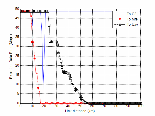
For each link type (that is, for each inter-asset pair), an ensemble of results were obtained by simulating the OFDM scheme mentioned previously for different specific channel realisations, and determining the most spectrally efficient modulation mode that could be supported without exceeding the target bit error rate requirement. From these ensembles, the probability of being able to use each modulation mode (each having a different data rate) was calculated. The data rate for each modulation mode was calculated assuming a half-rate coding scheme would be used to deal with residual bit errors, and also accounting for framing, channel estimation, and cyclic prefix overheads for the OFDM scheme. These probabilities along with the data rate for each modulation mode were used to calculate the expected data rate for each link type and link distance. These expected data rates are plotted in Figures 1 to 4.
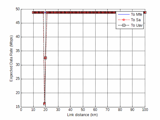
Figure 1 contains the results for all C2 uplinks, for link distances between 10 km and 100 km inclusive. Since the C2 and MFE have pencil-beam antennas achieving maximum gain in each others’ direction and due to the large gain and transmit power on the C2, this uplink always achieves the maximum data rate of 48.82 Mbps. On the other hand, for link distances of 19 km and 20 km, both the SA and the UAV experience lower data rates. This is due to the fixed orientations of the antennas assumed on these assets, and that their maximum antenna gain is at the horizon. It turns out that there is a null in the antenna beam patterns for these assets close to angles-of-arrival experienced at these link distances.
| Node Type | Transmit Power (watts) | Transmit/ Receive Gain (dBi) | Antenna Beam Type | Half Power (3-dB) Beamwidth |
|---|---|---|---|---|
| MFE | 20 | 9 | PENCIL | 54o in elevation and azimuth |
| UAV | 5 | 6 | OMNI | 26o in elevation, omnidirectional in azimuth |
| SA | 50 | 6 | OMNI | 26o in elevation, omnidirectional in azimuth |
| C2 | 100 | 25 | PENCIL | 9o in elevation and azimuth |
Figure 2 contains the results for the MFE uplinks. Due to the large receive gain for the C2, and the moderate transmit power and antenna gain on the MFE, the maximum data rate is achieved for all distances on the MFE-to-C2 link. However, for the uplinks to the SA and the UAV, a very rapid drop in expected data rate is observed for link distances beyond 7 km. This loss in data rate with increased link distance is in fact greater than that which would be expected for a pure line-of-sight (LOS) channel, even considering the fixed orientation of the antennas on the SA and the UAV. Further investigation revealed that much of the loss was due to destructive interference between the LOS signal and the ground-reflected signal. This is a also a common effect in terrestrial mobile radio systems where both the base station height and the mobile station height are considerably lower than the link distance (see, for example [14]).
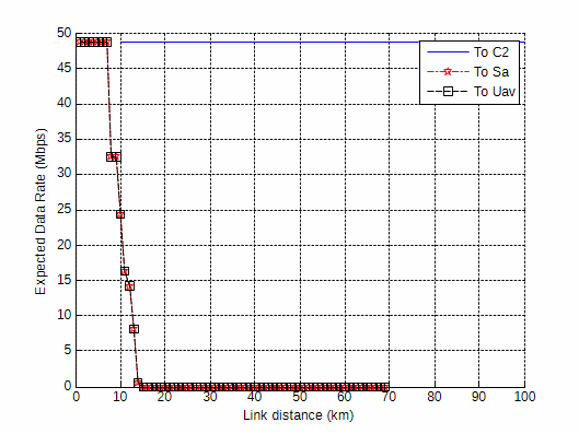
Figure 3 contains the results for the SA uplinks. The uplink to the C2 behaves similarly to the already discussed C2-to-SA link. However, an additional reduction in data rate is observed when the SA and C2 are separated by only 10 km. This is due to the proximity of the angle-of-departure for the LOS signal from the SA to the C2 with a null in the antenna beam pattern for the SA transmit antenna. A similar issue did occur for the C2-to-SA link. However, the higher transmit power for the C2 was enough to mask this effect in the C2-to-SA case. The link from the SA to the MFE behaved similarly to the MFE-to-SA link previously discussed, with the exception that the higher effective isotropic radiated power (EIRP, essentially the linear product of transmit power and gain) for the SA afforded a slight increase in expected data rate. Lastly, the SA-to-UAV link is noted to exhibit a gradual drop in expected data rate as might be expected with ordinary free-space loss. However, further investigation revealed it is also due to ground-reflections that in this case are at delays outside the sampling period, and cause frequency selective fading of the OFDM signal.
The results for the UAV uplinks are shown in Figure 4. Referring to Table 2, it should be noted that these uplinks are faced with the most demanding requirements. The UAV to MFE link exhibits similar behaviour to the MFE-to-UAV link shown on Figure 2. However, the performance is slightly worse due to the lower EIRP on the UAV. Also, excepting for the lower EIRP on the UAV, the UAV-to-SA link behaves in a similar fashion to the SA-to-UAV link described previously. Similar observations may be made when comparing the UAV-to-C2 link with the C2-to-UAV link.
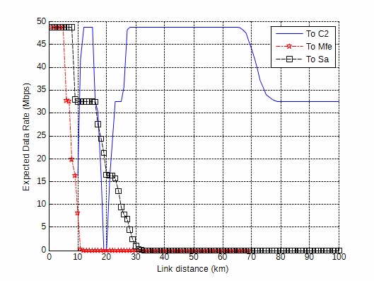
When jointly considering Figures 1 to 4 as well as Table 2, it is apparent that in order for a dynamic TDMA scheme at the MAC-layer to service all links at the required rates, it would at least be required to relay some of the UAV uplink data for the SA and the MFE via the C2, in the event that the distances from the respective assets were beyond approximately 20 km or 8 km. This is because beyond these approximate distances, the percentage of time required to serve the individual uplinks would be too large for all other uplinks to be supported (see [13] for details on the calculation of such percentages). In order to accommodate the necessary relays, there is some restriction imposed on the distance from the C2 to the UAV. Specifically, it would be better to locate the C2 between 30 km and 60 km, for the antenna orientation assumed. Of course, it may not be possible to do this in a practical scenario, in which case perhaps other antenna orientations may need to be considered for the UAV. Additionally, should the C2 become unavailable, an alternative relay source may need to be found, or a more robust, lower rate communications mode (not described explicitly in this paper), may be used to achieve some degraded level of communications over larger ranges between the remaining nodes.
Conclusions and recommendations
The feasibility of a small communications network for a simple scenario was investigated. Numerical results suggested that a four-node network with multiple video streams transmitted between appropriate tactical assets could be achieved when considering approximate SWAP constraints for each node. Suggestions were also given concerning MAC-layer design issues for the type of scenario considered. It was advised that a dynamic TDMA approach should be used and that the network should be ad hoc, or structured with a dynamically assigned master node. The impact of particular antenna orientations and the effect of signals from the ground were discussed. It was noted that the C2 node, with the greatest antenna gain and transmit power of all elements could be used effectively for relaying data, provided it was located at an appropriate distance from the remaining nodes. If this could not be accommodated in practice, other antenna orientations may need to be investigated. The impact of the C2 becoming unavailable need not cause catastrophic degradation to the network, should the advised approach be taken at the MAC layer. However, a lower rate, more robust communications mode may need to be used when the remaining nodes have large separations.
Whilst the scenario in this paper is somewhat simplistic, it demonstrates the feasibility of implementing tactical networks when considering practical constraints. Future work may involve consideration of robust low rate modes when relaying is not possible due to node damage, and scalability for larger networks. Currently, the specific development of the physical layer waveform is being considered in more detail, in parallel with the development of a demonstration platform using SDRs.
Acknowledgements
LMAES would like to acknowledge the strong contribution of the Defence Science and Technology Organisation (DSTO) and the Defence Systems Innovation Center (DSIC) to this endeavour, in particular the efforts of staff from Air Operations Division (DSTO), Centre for Defence Communications and Information Networking (The University of Adelaide) and Institute for Telecommunications Research (University of South Australia).
References
[1] “Joint Tactical Radio System: Connecting the Tactical Edge”, Joint Program Executive Office, available: http://jpeojtrs.mil/files/domains/JTRS_media_Updated_Jan09_final.pdf.
[2] D. Culpin, R. O’Dowd, and M. Davies, “Leverage of Commercial Technologies and Approaches to Support Networked Military Operations”, in Proc. International Data Links Symposium, Sydney, Australia, Aug. 2008.
[3] D. Winch, “Dynamic Tactical Networking Project—Phase One Work Program”, Internal Technical Report, Lockheed Martin Australia Electronic Systems, Feb. 2009.
[4] D. Winch, “Dynamic Tactical Networking Project—Phase One—Task 1—Report”, Internal Technical Report, Lockheed Martin Australia Electronic Systems, Mar. 2009.
[5] B.A. Fette, et. al., RF and Wireless Technologies, Newnes/Elsevier, Amsterdam, 2008.
[6] J. Asenstorfer, T. Cox, and D. Wilksch, “Tactical Data Link Systems and the Australian Defence Force (ADF)—Technology Developments and Interoperability Issues”, DSTO Technical Report DSTO-TR-1470, Feb. 2004.
[7] “AMF JTRS—A Bridge to Joint Communications”, in Insights, Lockheed Martin, pp. 20-21, Quarter 1, 2009, available: http://www.lockheedmartin.com/innovation/1Q-2009-Insights.pdf.
[8] “Time Division Multiple Access”, Wikipedia entry, available: http://en.wikipedia.org/wiki/Time_division_multiple_access
[9] “Wideband Networking Waveform Starter Kit”, Product brochure, Spectrum Signal Processing, available: http://www.spectrumsignal.com/products/pdf/WNW_Starter_Kit.pdf.
[10] L. Hanzo, C.H. Wong, and M. S. Yee, Adaptive Wireless Transceivers, John Wiley & Sons, West Sussex, 2002.
[11] B.E. White, “Tactical Data Links, Air Traffic Management, and Software Programmable Radios”, Digital Avionics Systems Conference, St. Louis, USA, Nov. 1999.
[12] I.D. Holland and W.G. Cowley, “Physical Layer Design for mm-Wave WPANs using Adaptive Coded OFDM”, Australian Communications Theory Workshop, Christchurch, New Zealand, Jan.-Feb. 2008.
[13] I.D. Holland, “Considerations and Results Concerning High-data-rate Mobile Tactical Networking”, MilCIS 2009, Canberra, Australia, Nov. 2009.
[14] A.F. Molisch, Wireless Communications, John Wiley & Sons, West Sussex, 2005.