
Volume 13, Number 2, July 2010
Component Impact Kill Criteria—an Experimental Study
- 1 FOI, Swedish Defence Research Agency, SE-164 90 Stockholm, Sweden.
Abstract
Vulnerability/lethality (V/L) tools used to assess weapons effects in targets often need some kind of rule to assess the status of each vital component being hit. The target functionality on a system level can then be decided based on which components are functional or non-functional (killed). Rules of this kind are often referred to as component kill criteria. Descriptions of component kill criteria and methods to assess them are rare in scientific journals, probably due to economic values, classified V/L tools, as well as classified input data to the tools. This paper presents the results from an experimental study of a target component, a relay, impacted by steel spheres and the component’s response to the impact. A first set of kill criteria based on impact energy and momentum are presented. Studies of the kind presented in this paper cannot be performed unless the component is cheap and readily available, conditions that many components in a military platform do not meet. For that reason and others discussed, methods and models for assessing component kill criteria should be derived from experimental studies on available components and then hopefully be sufficient also for component types that cannot be tested.
Introduction
Vulnerability and lethality (V/L) tools are used to assess or estimate the effects of a weapon in a target. The results are normally presented as probabilities of target incapacitation. These results are often referred to as kill probabilities or Pk’s, e.g. M (mobility) kill, F (fire power) kill, and K (catastrophic) kill [1]. The number of kill types and the true meaning of them vary in the various tools, which may cause interpretation problems.
V/L-tools that model the target on a component level, require some kind of rule to assess the status of each vital component after the hit. Depending on the type of tool the status can be described with:
- kill or no kill for codes that run several Monte Carlo cycles in a simulation to get an average result, or
- a probability of component kill for codes that give the result after just one simulation.
Xiangdong et al. [2] formulated a definition of damage criterion when stating that “the damage criterion is a judgement that is used to determine whether a component is damaged”. They continue by stating [2]: “According to the definition of the damage criteria of components, the damage criteria include two meanings. One is the definition of damage. Another is the relation between the damage degree of component and damage elements, which act on the component”. Ball [3] describes component damage as: “The inability of a component to provide the function(s) it was designed to provide is referred to variously as a component dysfunction, damage, failure, fault or kill depending upon the type of analysis being performed and the performing organization”. Obviously there is no standardized terminology. This is further emphasised by Driels [4] who describes the kill probability as function of impacting fragment velocity and mass; “fragility curve”.
Regardless of the type of code, there can be thousands of components in a target which all requires this kind of information, for all weapon effects (such as penetration, pressure, acceleration, heat, and so on) that the code handles. Unfortunately this information is often limited or even unavailable [5]. There are a few published scientific papers that acknowledge this problem by Putzar et al. [6] and Schäfer et al. [7] but focusing on space debris impact, and thus a high-velocity regime.
One way of obtaining the probability of component damage with respect to different kind of loads is to test them experimentally. Considering only damages due to penetration, however, there are an infinite number of combinations of penetrator mass, velocity, and impact direction. This in combination with the high price of some unique components for military platforms makes experimental studies hard.
This paper presents the results of an experimental study of impacts on a component and the component’s response to the impact. Steel spheres of three different diameters were used to impact the component. The component was a readily available low price relay. Based on the experimental results, a first set of kill criteria are proposed based on impact momentum and impact kinetic energy. A follow-up study to this study is planned, where the kill criteria will be evaluated by simulations, according to Hartmann [8], Eriksson and Hartmann [9], and Gustafsson and Karlsson [10].
Experimental testing
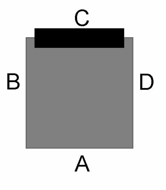
The experimental tests consist of two parts. First the ballistic limit V50 was estimated for the plastic shell of the relay. All four sides, see Figure 1, were considered identical in these tests, and thus neglecting the small differences that actually exist and also neglecting the top and bottom sides. The V50 was estimated for each projectile size in accordance with MIL-STD 662F [11], but without the use of the prescribed witness plate. A visual inspection was performed in order to differentiate partial penetration, PP, from complete penetration, CP. In this inspection complete penetration was defined as a clearly visible hole (even if the hole was smaller than the projectile), and if there was no evident damage or just one or several cracks it was defined as partial penetration.
| 1·V50 | 2·V50 | 3·V50 | 4·V50 | 5·V50 | |
|---|---|---|---|---|---|
| Projectile 1 | 3 × 4 | 3 × 4 | 3 × 4 | 3 × 4 | 3 × 4 |
| Projectile 2 | 3 × 4 | 3 × 4 | 3 × 4 | 3 × 4 | 3 × 4 |
| Projectile 3 | 3 × 4 | 3 × 4 | 3 × 4 | 3 × 4 | 3 × 4 |
| Designation | Measured diameter | Measured mass |
|---|---|---|
| 4 mm | 3.95 mm | 0.25 g |
| 6 mm | 6.35 mm | 1.04 g |
| 8 mm | 8.00 mm | 2.08 g |
The second part was the impact testing of the relays, complete with the plastic shell. The tests were designed according to Table 1, each side (excluding top and bottom) of the relays was impacted. The impact velocities were chosen as multiples of the estimated V50’s of the plastic shell. The aim-point was in the centre of the side facing the weapon. Since this target is small (approximately 25 × 23 mm2) it was assumed that the normal hit distribution from the weapon should give a hit point distribution all over the surface. If the target would have been larger, aim-points distributed over the surface would have been necessary.
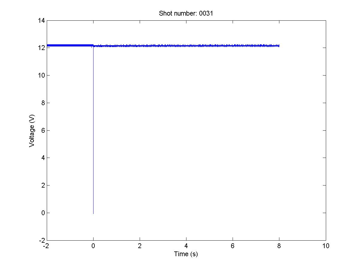
The output voltage was measured during impact in order to record any disturbances in power delivery. Whether this is important or not will depend on the equipment powered via the relay.
A new relay was used for each firing. With four sides per relay, three sizes of projectiles, five impact velocities and three repetitions of each combination gives a total of 180 shots and relays. Note that the V50 values will differ between the different projectile sizes, but at V50 each projectile will just be able to perforate the plastic shell.
It was decided that if all three repetitions of one combination of relay side, projectile size, and impact velocity rendered the relay non-functional, no higher impact velocities should be tested. In this case the relay is assumed to be rendered non-functional also by the higher impact velocities.
Equipment and setup
The projectiles used were roller bearing balls of steel, see Table 2 for more information. The hardness of the steel balls was not measured.
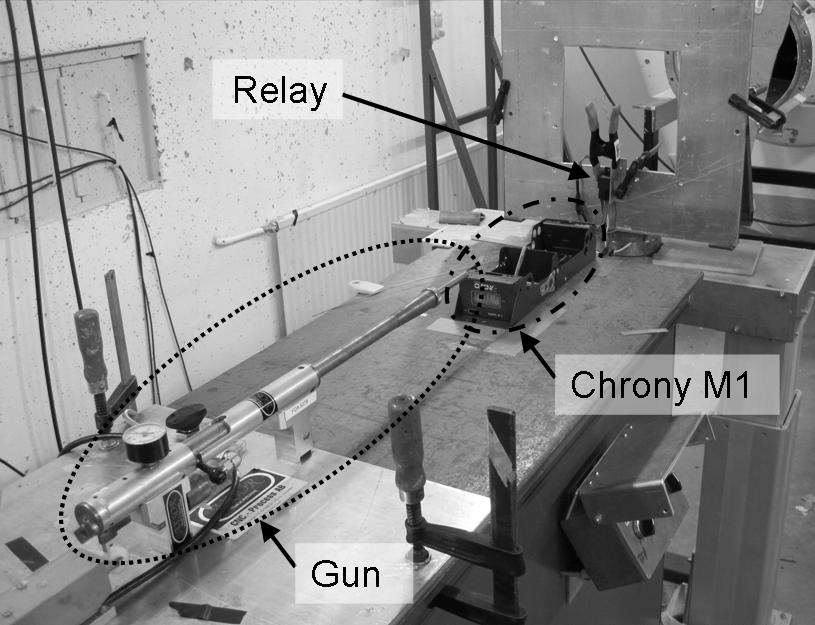
The projectiles were fired with a laboratory weapon (manufactured by Axsor) using compressed air instead of gun powder to accelerate the projectile. This weapon makes it possible to adjust and repeat the velocity of the projectiles with small differences. The targets were placed 600 mm from the weapon, and a Chrony M1 velocity meter 100 mm from the weapon, according to Figure 2. In a few preliminary firings to estimate the velocity reduction from the meter to the target, a second Chrony M1 replaced the target.
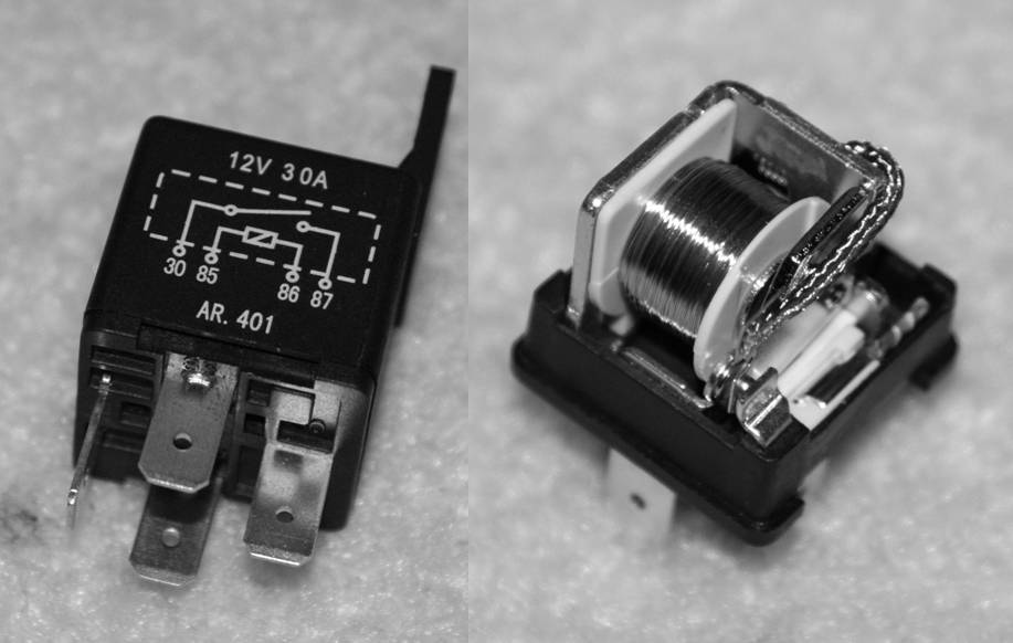
The relay type chosen was Biltema 42-301 (the actual manufacturer is unknown), as shown in Figure 3. This is a single circuit closing relay intended to be used for horns, extra headlights and similar equipment in cars. The maximum allowed electrical load is 12V, 30A.
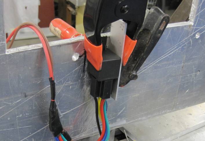
All relays were supported at the back side and clamped to a girder on the right hand side, viewed from the weapon as seen in Figure 4. In order to have the relays electrically loaded during the firing, a light bulb (H4, 12V, 45/55W) was connected to the consumer side of the relay, and a switch was connected to the manoeuvre side in order to operate the relay. An oscilloscope (LeCroy WaveJet 314) was connected to measure the output voltage at the consumer side during projectile impact.
The ballistic limit, V50 was estimated by firing on the plastic shell of the relay alone without any interior parts. This was to ensure that the boundary conditions would be as similar as possible to the complete relay but without the possibility of any interior parts supporting one or several sides.
Experimental results
Preliminary firings showed a velocity decrease of roughly 1 m/s from the velocity measurement unit to the target and this was assumed acceptable.
The hit point distribution shows that most shots hit relatively close to the centre of the impacted side of the relay. In a few cases the centre of the damage is located about 5−7 mm from the centre of the impact side.
The ballistic limit measurements for the different projectiles were conducted in accordance to MIL-STD 662F [11], but with a lower velocity span between the shots. A maximum span of 5 m/s was chosen due to the overall low velocities. Table 3 gives the results from the ballistic testing, neglecting the small differences between different relay sides. In Table 3 PP gives the two highest velocities for partial penetration, CP the two lowest velocities for complete penetration, Mean is the mean value of the measured velocities (the actual V50 according to MIL-STD 662F [11]) and V50 the rounded off ballistic limit velocity used in this study.
Tables 4, 5, and 6 give the results for the 4 mm, 6 mm and 8 mm projectile respectively. The function of the relay after impact is defined in the status column where;
- 0 denotes a fully operational relay;
- 1 denotes a relay that do not have any functionality and does not respond to two switches on and off;
- 2 denotes a relay that continues to deliver electricity after impact, but when turned of by the switch it cannot be turned on again;
- 3 denotes a relay that stops delivering electricity when hit, but regains its functionality when switched off and on; and
- 4 denotes a relay that continues to deliver electricity and can not be turned off by the switch.
A mistake was made in the beginning of the test series. When the 4 mm projectiles were fired with the lowest velocity (V50) only three relays were used and impacted at all sides. Since none of these relays showed any change in functionality they could all be given status 0 without redoing the tests.
| Proj. | PP (m/s) | CP (m/s) | Mean (m/s) | V50 (m/s) | ||
|---|---|---|---|---|---|---|
| 4 mm | 66.68 | 71.45 | 68.16 | 68.79 | 68.77 | 70 |
| 6 mm | 36.43 | 37.61 | 37.44 | 38.68 | 37.54 | 40 |
| 8 mm | 28.35 | 29.02 | 31.76 | 28.93 | 29.51 | 30 |
| Shot no. | Impact side | Velocity (m/s) | Status |
|---|---|---|---|
| 30 | A | 68.4 | 0 |
| 31 | B | 67.0 | 0 |
| 32 | C | 68.0 | 0 |
| 33 | D | 76.9 | 0 |
| 34 | A | 73.2 | 0 |
| 35 | B | 75.6 | 0 |
| 36 | C | 69.8 | 0 |
| 37 | D | 68.9 | 0 |
| 38 | A | 69.5 | 0 |
| 39 | B | 71.2 | 0 |
| 40 | C | 68.9 | 0 |
| 41 | D | 68.4 | 0 |
| 42 | A | 70.3 | 0 |
| 43 | B | 67.9 | 0 |
| 44 | C | 70.7 | 0 |
| 45 | D | 70.3 | 0 |
| 46 | A | 136.9 | 1 |
| 47 | A | 133.6 | 0 |
| 48 | A | 136.0 | 1 |
| 49 | B | 135.6 | 0 |
| 50 | B | 136.8 | 0 |
| 51 | B | 135.8 | 0 |
| 52 | C | 135.4 | 0 |
| 53 | C | 135.9 | 1 |
| 54 | C | 137.0 | 0 |
| 55 | D | 137.6 | 0 |
| 56 | D | 135.4 | 0 |
| 57 | D | 135.7 | 1 |
| 58 | A | 217.1 | 1 |
| 59 | A | 215.3 | 1 |
| 60 | A | 214.7 | 1 |
| 61 | B | 204.9 | 0 |
| 62 | B | 208.7 | 0 |
| 63 | B | 207.6 | 1 |
| 64 | C | 213.7 | 0 |
| 65 | C | 210.0 | 0 |
| 66 | C | 215.9 | 0 |
| 67 | D | 215.3 | 1 |
| 68 | D | 211.8 | 1 |
| 69 | D | 205.9 | 1 |
| 70 | B | 267.7 | 0 |
| 71 | B | 268.8 | 0 |
| 72 | B | 271.0 | 0 |
| 73 | C | 271.7 | 0 |
| 74 | C | 273.9 | 0 |
| 75 | C | 269.4 | 0 |
| 76 | B | 340.1 | 2 |
| 77 | B | 348.6 | 3 |
| 78 | B | 349.7 | 1 |
| 79 | C | 351.2 | 0 |
| 80 | C | 355.7 | 0 |
| 81 | C | 347.9 | 0 |
| 163 | C | 412.2 | 4 |
| 164 | C | 409.7 | 1 |
| 165 | C | 410.4 | 1 |
| Shot no. | Impact side | Velocity (m/s) | Status |
|---|---|---|---|
| 82 | A | 40.9 | 0 |
| 83 | A | 43.3 | 0 |
| 84 | A | 42.3 | 0 |
| 85 | B | 42.1 | 1 |
| 86 | B | 40.3 | 0 |
| 87 | B | 41.2 | 0 |
| 88 | C | 39.9 | 0 |
| 89 | C | 39.5 | 0 |
| 90 | C | 37.9 | 0 |
| 91 | D | 40.0 | 0 |
| 92 | D | 37.7 | 0 |
| 93 | D | 36.7 | 0 |
| 94 | A | 78.5 | 1 |
| 95 | A | 80.3 | 1 |
| 96 | A | 78.3 | 1 |
| 97 | B | 79.3 | 0 |
| 98 | B | 79.6 | 0 |
| 99 | B | 77.8 | 0 |
| 100 | C | 76.5 | 0 |
| 101 | C | 78.8 | 0 |
| 102 | C | 79.5 | 1 |
| 103 | D | 79.3 | 1 |
| 104 | D | 79.5 | 3 |
| 105 | D | 78.8 | 1 |
| 106 | B | 120.9 | 0 |
| 107 | B | 120.8 | 0 |
| 108 | B | 121.6 | 1 |
| 109 | C | 121.0 | 0 |
| 110 | C | 120.8 | 0 |
| 111 | C | 120.7 | 0 |
| 112 | B | 159.1 | 1 |
| 113 | B | 159.3 | 1 |
| 114 | B | 150.9 | 1 |
| 115 | C | 167.8 | 1 |
| 116 | C | 160.8 | 1 |
| 117 | C | 162.4 | 1 |
| Shot no. | Impact side | Velocity (m/s) | Status |
|---|---|---|---|
| 118 | A | 29.6 | 0 |
| 119 | A | 29.0 | 0 |
| 120 | A | 28.9 | 0 |
| 121 | B | 29.9 | 0 |
| 122 | B | 30.7 | 0 |
| 123 | B | 29.8 | 0 |
| 124 | C | 30.6 | 0 |
| 125 | C | 30.0 | 0 |
| 126 | C | 30.4 | 0 |
| 127 | D | 30.4 | 0 |
| 128 | D | 30.4 | 0 |
| 129 | D | 30.2 | 0 |
| 130 | A | 56.2 | 1 |
| 131 | A | 63.8 | 1 |
| 132 | A | 59.4 | 1 |
| 133 | B | 59.3 | 0 |
| 134 | B | 61.8 | 2 |
| 135 | B | 62.4 | 0 |
| 136 | C | 62.6 | 0 |
| 137 | C | 62.5 | 0 |
| 138 | C | 55.4 | 0 |
| 139 | D | 55.2 | 1 |
| 140 | D | 59.1 | 2 |
| 141 | D | 60.1 | 1 |
| 142 | B | 87.5 | 4 |
| 143 | B | 87.2 | 1 |
| 144 | B | 87.3 | 4 |
| 145 | C | 87.0 | 0 |
| 146 | C | 86.8 | 0 |
| 147 | C | 86.1 | 2 |
| 148 | B | 123.1 | 1 |
| 149 | B | 122.2 | 1 |
| 150 | B | 122.5 | 1 |
| 151 | C | 122.2 | 4 |
| 152 | C | 121.8 | 1 |
| 153 | C | 122.0 | 4 |
| 154 | C | 153.1 | 1 |
| 155 | C | 153.0 | 1 |
| 156 | C | 153.5 | 0 |
| 157 | C | 180.6 | 4 |
| 158 | C | 180.8 | 1 |
| 159 | C | 181.0 | 4 |
| 160 | C | 212.7 | 1 |
| 161 | C | 213.0 | 4 |
| 162 | C | 212.0 | 1 |
In many cases a short fluctuation in the output voltage was recorded at the time of impact. A typical result is presented in Figure 5, where a short voltage dip at the time of impact (t=0) is evident.
Evaluation of results
The experimental results are summarized in Table 7, where the grey cells represent those cases in which it is assumed that all three relays would have been killed based upon tests with lower velocities. A relay was considered killed if the status after impact was anything but 0. Note that for the 4 mm projectile and v = V50, four shots were fired against each side, with no relay incapacitated. In Table 7 this is presented as a 100% survival rate of three relays, in order to be comparable with the other results.
During the experimental part of the study, status 4 was also considered as a functional relay. This is the reason to why the 8 mm spheres were fired at side C at higher velocities even when Table 7 shows that the experiments could have been interrupted after impact velocity v = 4·V50.. In the evaluation of the results, a relay with status 4 was considered to be killed.
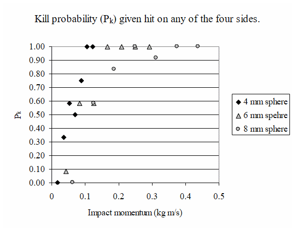
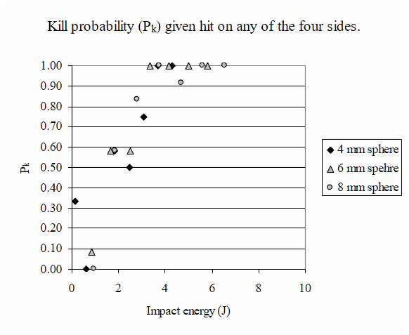
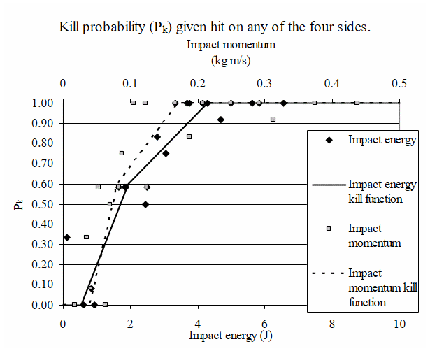
From Table 7 it is obvious that the relays are most sensitive to impacts on side A and least sensitive to impacts on side C. Despite these differences, an easy to use kill criterion should preferably be independent of impact direction and impact position. Figures 6 and 7 present the kill probabilities due to impact on an arbitrary side as functions of impact momentum and kinetic energy respectively, where the kill probabilities are defined as the average kill probability from impacts on the four sides. The impact momentums and kinetic energies were calculated using the measured masses of the spheres and the corresponding rounded-off ballistic limit velocity, V50, according to Table 3.
| Proj. | Number of surviving relays (of 3) | |||||||
|---|---|---|---|---|---|---|---|---|
| Impact side | Normalized impact velocity (v/V50) | |||||||
| 1 | 2 | 3 | 4 | 5 | 6 | 7 | ||
| 4 mm | A | 3 | 1 | 0 | 0 | 0 | 0 | 0 |
| B | 3 | 3 | 2 | 3 | 0 | 0 | 0 | |
| C | 3 | 2 | 3 | 3 | 3 | 0 | 0 | |
| D | 3 | 2 | 0 | 0 | 0 | 0 | 0 | |
| 6 mm | A | 3 | 0 | 0 | 0 | 0 | 0 | 0 |
| B | 2 | 3 | 2 | 0 | 0 | 0 | 0 | |
| C | 3 | 2 | 3 | 0 | 0 | 0 | 0 | |
| D | 3 | 0 | 0 | 0 | 0 | 0 | 0 | |
| 8 mm | A | 3 | 0 | 0 | 0 | 0 | 0 | 0 |
| B | 3 | 2 | 0 | 0 | 0 | 0 | 0 | |
| C | 3 | 3 | 2 | 0 | 1 | 0 | 0 | |
| D | 3 | 0 | 0 | 0 | 0 | 0 | 0 |
| Impact energy | Impact momentum | ||
|---|---|---|---|
| Energy (J) | Pk (-) | Momentum (kg m/s) | Pk (-) |
| 0.00 | 0.00 | 0.00 | 0.00 |
| 0.53 | 0.00 | 0.04 | 0.00 |
| 1.94 | 0.60 | 0.08 | 0.60 |
| 4.29 | 1.00 | 0.17 | 1.00 |
| 10.00 | 1.00 | 0.50 | 1.00 |
Figure 8 combines the kill probabilities as functions of both impact momentum and energy, together with graphical piecewise linear estimates of kill probability functions. The break points for these functions are also tabulated in Table 8.
Discussion
The need of component kill criteria to be used in component based vulnerability/lethality tools is unambiguous. Without them, the status of the individual components cannot be evaluated, leading to an inability to evaluate the functional status of the target on a system level after being subjected to an attack.
This work shows that it is possible to, at least for some types of components, perform experimental studies in order to estimate kill criteria based on physical properties of the impactor. There are, however, a number of problems related to experimental studies, the first being availability and price of components. A component like the relay used here is cheap and available in almost any quantity needed. This is mandatory for experimental assessments of component kill criteria. Components specially designed for a fighter air craft, a main battle tank or a ship are often only produced in small quantities to be enough for the platform production and a few spare components. In order to assess the kill criteria for these exclusive components other means and methods must be available, but these methods should first be validated on components that can be experimentally investigated.
Another problem with experimental testing of components is to disperse the impact points all over the component. For a small component it might be enough with the normal hit point distribution when firing, but for larger components the aim points must probably be predefined over each surface. The normal hit point distribution was enough in this case, but even for a slightly larger component the aim point should have been dispersed in a controlled manner.
A third problem, not limited to experimental studies, is how to decide when a component is killed. Some components might operate with a reduced capacity after being damaged. For the relatively simple component used in this study five different statuses after impact was found, four of which was defined as a component kill. How this best is evaluated might, unfortunately, vary from time to time depending on component use, and the component’s relation to other components.
If the component has significant empty volumes, where there are no internal vital parts, the kill probability will often not reach 1.00. This is partly due to what is called “vulnerable area” [12]. On the other hand, if the component is small and the projectile has a size of the same magnitude, the complete face area will probably be vulnerable.
It is evident that the component used in this study has faces that are more vulnerable to impacts than others. According to this, the vulnerability/lethality assessment tools should preferably be able to handle different kill criteria for different faces of a component. This is probably uncommon in the tools used today. For that reason, the results are averaged over all four tested surfaces.
A kill criterion described with physical properties of the impactor is easily shared between different parties. Physical properties are also easy to measure in experimental studies. The vulnerability/lethality tools on the other hand might require kill criteria described by other measures, such as penetration capacity or damaged volume in the component. This means that for many tools there is also a need for transformation rules from physical to calculated measures, before the kill criteria can be used.
Acknowledgements
This experimental study was founded by the Swedish Armed Forces. Mr. Jonas Irving of the Swedish Defence Research Agency conducted the experimental testing and related work.
References
[1] P. Tanenbaum, “Vulnerability/Lethality Methodology”, Course documentation of Vulnerability / Lethality, May 21−24 1990, Balitmore MD, Computational Mechanics Associates.
[2] L. Xiangdong, Z. Yunfa, and W. Huizhi, “A Research on the Damage Criteria of Target Components in Vulnerability Assessments”, Proceedings of 17th International Symposium on Ballistics, Midrand, South Africa, 23−27 March 1998.
[3] R. Ball, The Fundamentals of Aircraft Combat Survivability Analysis and Design, AIAA Education Series, 2003.
[4] M. Driels, Weaponeering—Conventional Weapon System Effectiveness, AIAA Education Series, 2004.
[5] M. Hartmann, “Component Kill Criteria—A Literature Review”, Swedish Defence Research Agency, FOI-R--2829--SE, August 2009.
[6] R. Putzar, F. Schaefer, and M. Lambert, “Vulnerability of Spacecraft Harnesses to Hypervelocity Impacts”, International Journal of Impact Engineering, Vol. 35, pp. 1728−1734, 2008.
[7] F. Schäfer, S. Ryan, M. Lambert, and R. Putzar, “Ballistic Limit Equation for Equipment Placed Behind Satellite Structure Walls”, International Journal of Impact Engineering Vol. 35, pp. 1784−1791, 2008.
[8] M. Hartmann, “Methodology for Decisions for Kill Criterion of Components—A First Step”, Swedish Defence Research Agency, FOI-R--1755--SE, November 2005 (in Swedish).
[9] I. Eriksson and M. Hartmann, “A Method for Assessing Kill Criteria for Critical Components in Survivability Codes”, Proceedings of 3rd European Survivability Workshop, ENSICA, Toulouse, France, 16−19 May 2006.
[10] H. Gustafsson and P. Karlsson, “Produce Criteria’s for Vital Components by Simulations”, Proceedings of 3rd European Survivability Workshop, ENSICA, Toulouse, France, 16−19 May 2006.
[11] MIL-STD-662F, V50 Ballistic Test For Armor, Department of Defense, USA, 18 December 1997.
[12] T. Klopcic, Component PK|H (PD|H, PI|H) Exercise, 26 March 1992, Army Research Laboratory, ARL-SR-8, March 1994.