
Volume 13, Number 1, March 2010
Evaluation System For Laser Target Designators
Abstract
High-repetition-rate laser target designators (LTD) have proved their usefulness in warfare. The semi-active laser guidance technique has a LTD and precision laser guided bomb (LGB) working together with a unique pattern of laser pulses. This unique pattern or code of laser pulses is programmable through the LTD and is known to its counterpart weapon delivery system before an operation. A weapon’s sensors detect a coded laser spot, which is created by a LTD illuminating the target. The laser spot clearly marks the target to an aerial attacker or guided weapon. The programmable nature of laser pulse repetition rates makes these systems sophisticated, but these systems are also vulnerable to time-dependent instability, which in turn decreases the accuracy of the desired pattern or code. Hence, to assure high effectiveness of these systems, they must be regularly evaluated. This paper describes a system called a Laser Spot Detector (LSD), which evaluates the performance of a LTD by detecting the pulsed laser emitted by the LTD with a pulsed laser source either working in the near-IR or eye-safe range. The pulse repetition frequency (PRF) of a pulsed LTD is set to be its unique PRF code for ongoing missions and thus, an LSD can be effectively used in validating the codes emitted by LTD, thereby enhancing the efficacy of precision-guided munitions.
Introduction
High-repetition-rate laser target designators (LTD) have proved their usefulness in warfare [1]. The semi-active laser guidance technique has a LTD and precision laser guided bomb (LGB) working together with a unique pattern of laser pulses [2]. This unique pattern (or code) of laser pulses is programmable through the LTD and is known to its counterpart weapon delivery system before an operation. A weapon’s sensors detect a coded laser spot, which is created by a LTD illuminating the target. The laser spot clearly marks the target to an aerial attacker or guided weapon.
The programmable nature of laser pulse repetition rates makes these systems sophisticated, but these systems are also vulnerable to time-dependent instability, which in turn decreases the accuracy of the desired pattern or code. Hence, to assure high effectiveness of these systems, they must be regularly evaluated [3].
This paper describes a system called a Laser Spot Detector (LSD), which evaluates the performance of a LTD by detecting the pulsed laser emitted by the LTD with a pulsed laser source either working in the near-IR or eye-safe range. The pulse repetition frequency (PRF) of a pulsed LTD is set to be its unique PRF code for ongoing missions and thus, LSD can be effectively used in validating the codes emitted by LTD, thereby enhancing the efficacy of precision-guided munitions.
The need
An LTD is a laser light source, which is used to illuminate a target on the battlefield. LTDs provide precision targeting for laser-guided weapons such as LGBs. Examples of these precision munitions include the Paveway series of bombs, and Lockheed-Martin’s Hellfire missile. LTDs may be mounted on aircraft, ground vehicles, or handheld [4]. Forces of different countries employ different types of laser designators and rangefinders, permitting them to designate targets for aircraft flying overhead.
When a designator is used to mark a target, the beam it radiates is invisible because most of the laser designator sources produce 1064 nm light. Another important feature is that it does not illuminate the target continuously. Instead, a series of coded pulses of laser-light are fired. These pulses are coded in terms of time interval between two consecutive pulses and this time interval is resolved to the level of one microsecond. These light pulses are scattered of the target and then detected by the seeker on the laser-guided munition, which steers itself towards the centre of the scattered signal. Before it steers, it locks on to radiation only if it decodes the pulses and the code matches with that preprogrammed in the memory of the LGB.
LGBs come with their complimentary laser-designating pod or a source. The Paveway series of LGBs are state-of-the-art systems with various versions and those have been carried by various platforms such as Eurofighter, F-18, Mirage, and many more. These LGBs have been used in combat since the Vietnam War. It has been observed during the Kargil War (1999) that most of the LGBs did not lock on to the coded pulses reflected by the target, even though pulses were of high energy—that is, more than recommended 50 mJ of energy for 5 km range. The reason for this was the LTD producing different PRF code from the one, with which the LGB was programmed. This happens mainly due to the long instability of processor clock or drift produced in the electronic circuits with time. Hence the need arises for periodic evaluation of LTDs, primarily PRF, so that corrective measures can be taken to counter these time-dependent drifts. At present no LTD comes with its evaluation system, therefore, there is a need to design and develop a LSD system, which can evaluate LTDs comprehensively.
System design
There are four parameters that have been considered while designing an LSD. The first parameter, which has been discussed so far, is PRF, and is defined as the time interval between two consecutive pulses. Second is identification of friend or foe (IFF), which is an algorithm, used by LGB to compare the code of received pulses with the preprogrammed code. The third is field-of- view (FOV), which is defined as the maximum possible angle between optical axis of LGB and the direction of detectable reflected laser pulses irrespective of distance between target and guided munitions. Another parameter is sensitivity, which defines the minimum detectable power by the sensor of LGB. LSD comprises an optical assembly, an sensor assembly, an analogue processing assembly, and a microcontroller based assembly, as shown in block diagram of the system in Figure 1.
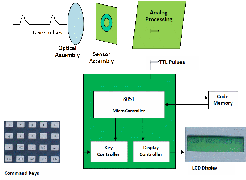
Optical assembly. This is the front assembly of the LGB system and its function is to collect the pulsed radiation falling on the system and focus it on to the optical sensor. It contains a convex lens and its placement with respect to the sensor decides the FOV of the system. Implementation of FOV through this assembly is discussed later.
Sensor assembly. This assembly consists of a PIN photodiode which converts the pulsed laser signal into a pulsed electrical signal. This assembly is critical in terms of assuring the sensitivity of the system
Analogue processing assembly. Laser pulses have a pulse width around 20−50 ns and these pulses, once detected and converted in to an electrical signal by the sensor assembly, are fed to the analogue processor. These pulses are stretched to around 5 µs width and voltage levels are set to TTL logic using a comparator, as shown in Figure 2. This is done because, for microcontroller to sense a pulse, its pulse width needs to be at least 1 µs.

Microcontroller-based assembly. This is the central processing assembly and it communicates with a keypad, an LCD, and system memory. Its main functions in the LSD are:
- implementation of PRF Decoder, and
- implementation of IFF.
Functionality of the system
The LSD is a standalone system with a weight of around 1.5 kg, and is designed for field evaluation of LTDs. As discussed earlier, it evaluates a number of parameters and this can be done by performing a sequence of operations.
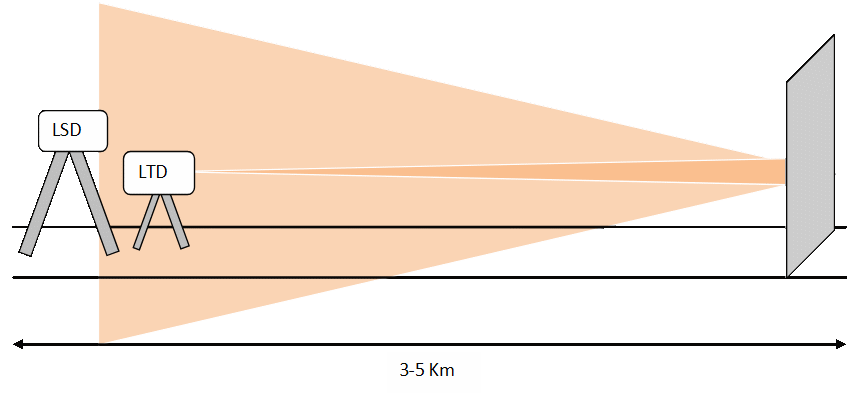
Experimental set up. Land-based LTDs illuminate land-based targets from a distance of ~3−5 km and reflected energy is collected by the LGB seeker. An open field with aligned marks separated by 3−5 km is required for the evaluation. The LTD and LSD can be placed at one of these two marks and a plane surface is placed vertical on another mark. Both, the LTD and LSD can be placed on goniometers, which are fixed on tripods or another platform.
Figure 3 shows the field evaluation set up for the LTD and the LSD placed next to it. A laser is fired from the designator and reflected pulses are detected by the LSD. Both systems are placed on goniometers to evaluate operation in FOV.
Operations for evaluation:
1. PRF codes are input to the LSD memory, up to a maximum of 20 codes.
2. Program the LTD with a PRF code other than the 20 codes stored in the LSD and fire the coded pulses onto the plane surface placed at distance (3−5 km). Reflected energy will be collected by the sensor of the LSD and it displays the value of PRF code generated by the LTD. Verify that the code decoded is same as the LTD’s code and LSD displays it as an unfriendly code.
3. Program the LTD with a PRF code, one of the 20 codes stored in LSD and fire the coded pulses onto the plane surface placed at a distance. Verify that the code decoded and displayed by the LSD is the same as the LTD’s code and the LSD displays it as a friendly code.
4. Repeat the operation for a number of codes and verify that PRF decoder accuracy stays ±1 µs and the IFF feature correctly distinguishes between friendly and unfriendly codes.
5. Change the angle at which the LSD is placed over the goniometer and verify that the LSD successfully performs 1−4 steps for all angles up to ±20º.
Criticalities of design
A number of critical issues have been addressed while designing this system.
Implementation of PRF decoder
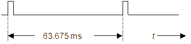
For an LGB to lock on to coded pulses, which are transmitted by an LTD, it has to have certain parameters of coded laser pulses within its limit. Most of the LTDs, operational in various forces, generate the programmable PRF code within the range of 10−20 Hz. Thousands of codes are possible with a resolution of 1 µs. PRF codes represent the time interval between pulses and thus are represented in the time domain as shown in Figure 4. For example, 10 Hz corresponds to 100 ms and 20 Hz corresponds to 50 ms. If 63.675 ms is the code chosen for a specific mission and preprogrammed in the LGB before mission, the LTD has to generate exactly the same code, once it is programmed through its keypad.
Due to long-term instability, the frequency generated by the laser (LTD) may vary, causing the change in the value of clock to the master controller. The master controller in the LTDs decides the number of clocks required for a particular code to be generated and hence, changes in the value of clock eventually leads to time differences between programmed PRF codes and those generated. This small drift leads to wastage of guided munitions as it receives a slightly different code to that to which it is supposed to respond. Hence, LTDs need to be evaluated for the full possible range of its PRF code values.
An 8051 microcontroller is used in the capture mode to collect the value of a 16-bit timer when the 8051 senses a falling edge at one of its data ports. The system goes into detection mode whenever a command is given through the keypad and the 8051 is set. Whenever any falling edge occurs, the value of the 16-bit timer at that instant is stored in lower and higher bytes of capture register, which can be placed in separate RAM space. These two registers capture the timer value at the second edge as well, which can also be kept in a separate memory. In the mean time if there is any overflow of the timer, a counter is incremented each time the control goes to the interrupt service routine (ISR). A clock of 1 MHz (1 µs in the time domain) is provided to the timer. The PRF code is calculated with the following algorithm:
- If value of timer at first edge is =FIRST
- If value of timer at second edge is = SECOND
- Number of overflows= OVERFLOW
- Then the value of PRF code in terms of number of clocks of 1 µs is:
if (SECOND > FIRST )
Time = [{(OVERFLOW) * (65356) + (SECOND-FIRST)}] µs
else
Time = [{(OVERFLOW-1) * (65356) + (FIRST-SECOND)}] µs
This value is represented in terms of milliseconds and programmed in the LCD in real time through the LCD controller. Results of the PRF decoder algorithm were validated by a standard 1 GHz frequency counter for a PRF code range 20−200 ms, which includes the operational range of LTDs—that is, 50−100 ms. This system decodes all possible PRFs of LTDs and simultaneously stores these values in a separate block of the system memory. The system was tested outdoors for different possible values of PRF. A LTD with output ~60 mJ was programmed with certain listed PRF codes. The laser output was modulated with PRF code and short pulses are fired one by one after PRF time interval.
Table 1 displays the results of experiments conducted with an LTD and the LSD using the above mentioned experimental set up. These readings show that the LSD differentiates two PRF codes separated by 1 μs. For all the readings between 50 ms and 100 ms, the LSD decodes the PRF accurately and if the PRF increases beyond 125 ms, it may sometimes give an inaccuracy of 1 μm, which is because of instabilities in the clock. To reduce this instability is the most critical part of the design. The frequency of the crystal can be stabilized to a maximum realizable value with the help of capacitors placed in parallel with the crystal oscillator. Frequency output of any oscillator depends upon its capacitance; hence by trimming the capacitance value, we can achieve frequency output to be closest to the expected value. Sometimes inaccuracy in the LTD results in inaccurate PRF measurement, hence a well characterized and evaluated LSD assures the user of accurate decoding of PRF and helps evaluate the LTD.
Implementation of IFF
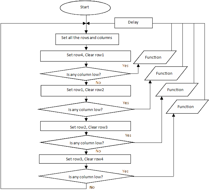
The key controller is the monitor program for the system and the microcontroller boots to the key command search routine. Figure 5 displays the flowchart of the monitor program. It shows how processor of the LSD detects the commands of the user. Before the LSD decides whether a code is friendly or not, friendly codes are stored in the memory through command keys. Once a friendly code is preprogrammed in the LSD, it is stored in the separate memory. Serial memory is preferred over parallel memory because it is controlled by two signals in comparison to 10 signals in the case of parallel memory. The 8051 microcontroller works as a master and IC 24C08 works as slave in bidirectional data transfer. I2C protocol is followed in this communication and SDA (data line) and SCL (clock) are the two lines used. Clock to the slave (memory) is provided by the master (microcontroller) and they communicate with the speed of the clock. The slave is addressed by the master with a unique command byte and this command byte once acknowledged by the slave, as shown in Figure 6, leads to data transfer. Each PRF code consists of six digits and this code is stored in the serial memory in six BCD packed bytes.
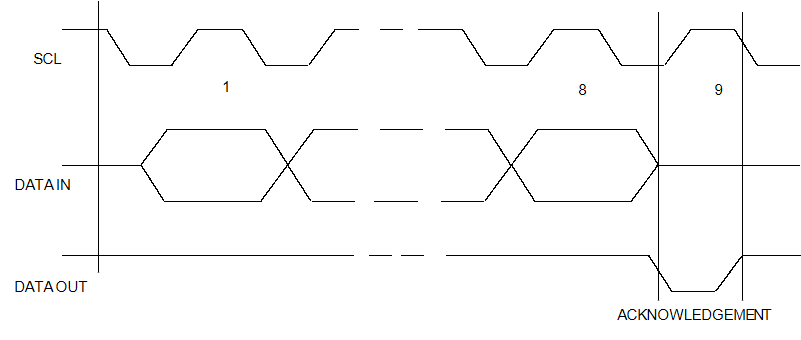
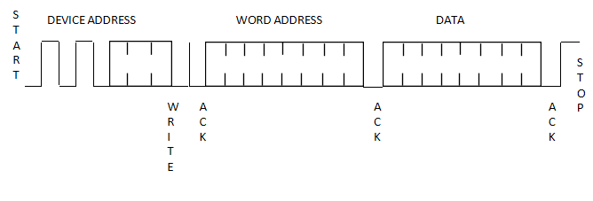
Similarly, when the PRF code is received by the system, it is automatically stored in the specific section of memory. During a byte write of a PRF code, the device address is communicated, followed by address of the byte and finally data contents are sent as shown in Figure 7.
Now the master sweeps through whole memory, reading all the bytes of preprogrammed codes and checks whether the decoded code matches with any of the friendly codes. These friendly codes are previously stored by the user and these are saved in memory as a pack of six bytes and all these codes are stored one by one in contiguous memory locations. However, addressing of locations for storage is done through programming only. The master reads the first six bytes and compares it with the decoded six bytes. If these two sets of bytes match, the LCD displays that it is a friendly code. In a similar situation, the LGB also sweeps through its preprogrammed code and tries to match it with the decoded code, and once it matches, the LGB locks onto that pulse-coded radiation. During scanning through memory, the master has to read successive bytes and this is followed after a device address request by the master, as shown in Figure 8.

Thus IFF feature is implemented in real time by the key controller and I2C protocol, although friendly and unfriendly codes can be separately scanned using different command keys of the system. Experiments for IFF were carried out at 3 km long range and it was found that the LSD accurately gave an indication in the display regarding friendly and unfriendly codes. Some friendly codes were stored in the system before, these were:
1. 23.444ms.
2. 65.535ms.
3. 110.110ms.
PRF codes were fired from the LTD and the response of the LSD are tabulated in Table 2.
Experiments reveal that the LSD responded with friendly codes for preprogrammed codes in system memory and unfriendly codes for those not stored in system. It is seen that the system differentiated even 1 µs difference in PRF and accurately categorized each decoded PRF. Similarly, an LGB will not lock on to any code, where the difference is as small as 1 µs from its pre-programmed code.
Implementation of field-of-view
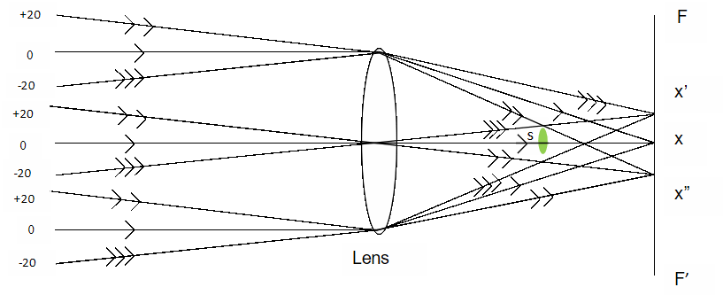
The FOV of LGB seekers is generally around ±20 degrees and reflected laser pulses falling onto the seeker within this angle have to be detected provided it is above the threshold of sensitivity of the detector. The optical assembly of the LSD is a lens (5 cm diameter and 5 cm focal length) and it is mounted just in front of the laser sensor (photodiode). The LTD radiation will be incident on the sensor after being reflected from a target placed within the FOV of the LSD. The design of the optical assembly is based on a ray diagram as shown in Figure 9. It shows the placement of the sensor with respect to the lens having focal point at x in the focal plane FF’. Three different sets of rays, which are incident on the lens from three different possible angles of 0°, +20°, −20°, converge at points x, x’ and x” respectively on focal plane. The sensor (s) has to be placed at a point where it is always over filled by the laser radiation falling from an angle −20° to +20°. The sensor shown in Figure 9 is located 2.5 cm from the lens and is covered by refracted laser radiations which are incident on the front end assembly from any angle between ±20 degrees. Experiments were conducted at the 3 km range to determine the LSD’s behavior against laser pulses falling on it from an LTD at an angle. These results are shown in Table 3.
Experiments were conducted by placing the LSD on a digital goniometer and a programmable LTD was used over a range of 3 km. Results reveal that when the angle between two systems exceeds 20° on either side, the LSD does not sense even the considerable amount of signal. When the angle was further reduced below 20°, the LSD decoded PRF of the LTD with the desired accuracy. LGBs have a FOV of around ±20º and when pulses are fired at the LSD from an angle with in this range, it responds to radiation as expected.
Implementation of sensitivity
Sensitivity is a critical parameter of a system evaluating an LTD and is referred to be the minimum detectable power of the LSD sensor. This minimum detectable power is the amount of power that the LGB seeker is able to detect at long range. Long range for LGB strike is supposed to be around 8−10 km and at this distance, the LGB starts detecting the coded radiation, which is being reflected by the target. Typically LGB seekers are designed to be sensitive to the radiation density ~ 1 µW/cm². The LSD has a front-end sensor, which is a photodiode and in response to the minimum detectable power density falling on its surface, it generates sufficient current in a pre-amplifier circuit, which is converted to voltage through the trans-impedance configuration of the pre-amplifier. Figure 10 shows the response of the photodiode in the desired wavelength range.
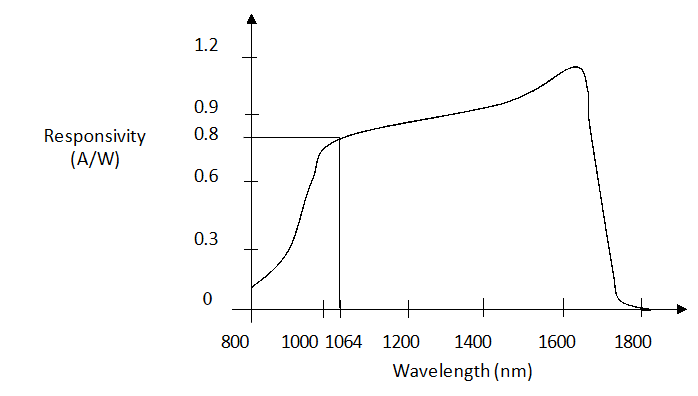
The sensor is a pin photodiode and is chosen such that it detects eye-safe wavelengths, including 1540 nm. Although most of the LTDs are still operating at 1064 nm, there is a trend to move to eye-safe wavelengths. The responsivity of the photodiode is roughly around 0.8 A/W and the minimum detectable power 1 µW/cm² falling on 1 mm² area, generates a current of 0.8×0.000006×0.01 = ~50nA. The preamplifier circuit, used in trans-impedance configuration converts this 50 nA current into voltage of 50 nA×10 MΩ = ~ 500 mV. This voltage level is sufficient to measure the PRF code.
Conclusion
An LSD is a state-of-the-art system which complies with all basic technical specifications of the LGB Delivery Evaluation System. It has significant role to play in periodic characterization and evaluation of various LTDs and hence provides a level of confidence in LGB delivery systems. Experiments were conducted in harsh environmental conditions and have revealed that a system such as an LSD can assure highly successful field results of any existing laser designation system.
Acknowledgements
1. Mr. A. K. Maini, Director, LASTEC, for his constant motivation and encouragement in the development of the system and this paper.
2. Mr. Ajay Sharma, Sc ‘F’, LASTEC, for his useful suggestions on writing this paper.
3. Ms. Varsha Agrawal, Sc ‘D’, LASTEC, for her technical and motivational contribution in development of this system and paper.
| S No. | PRF Code programmed in LTD(ms) | PRF Code displayed in LSD(ms) | S No. | PRF Code programmed in LTD(ms) | PRF Code displayed in LSD(ms) |
|---|---|---|---|---|---|
| 01 | 20.000 | 20.000 | 13 | 90.111 | 90.111 |
| 02 | 20.001 | 20.001 | 14 | 99.999 | 99.999 |
| 03 | 23.444 | 23.444 | 15 | 100.000 | 100.000 |
| 04 | 23.445 | 23.445 | 16 | 110.110 | 110.110 |
| 05 | 30.399 | 30.399 | 17 | 125.678 | 125.678 |
| 06 | 30.400 | 30.400 | 18 | 125.679 | 125.679 |
| 07 | 39.999 | 39.999 | 19 | 133.333 | 133.333 |
| 08 | 40.000 | 40.000 | 20 | 133.333 | 133.332 |
| 09 | 50.000 | 50.000 | 21 | 165.987 | 165.987 |
| 10 | 50.001 | 50.001 | 22 | 165.987 | 165.986 |
| 11 | 65.535 | 65.535 | 23 | 200.000 | 200.000 |
| 12 | 75.100 | 75.100 | 24 | 200.000 | 199.999 |
| S No. | PRF Code LTD(ms) | PRF Code LSD(ms) | Display |
|---|---|---|---|
| 01 | 20.000 | 20.000 | Unfriendly code |
| 02 | 23.444 | 23.444 | Friendly code |
| 03 | 23.445 | 23.445 | Unfriendly code |
| 04 | 30.399 | 30.399 | Unfriendly code |
| 05 | 65.534 | 65.534 | Unfriendly code |
| 06 | 65.535 | 65.535 | Friendly code |
| 07 | 65.536 | 65.536 | Unfriendly code |
| 08 | 90.111 | 90.111 | Unfriendly code |
| 09 | 110.110 | 110.110 | Friendly code |
| 10 | 133.333 | 133.333 | Unfriendly code |
| S No. | PRF(ms) of LTD | Angle (degrees) | Code @ LSD | S No. | PRF(ms) of LTD | Angle (degrees) | Code @ LSD |
|---|---|---|---|---|---|---|---|
| 01 | 23.445 | 0 | 23.445 | 11 | 30.399 | 0 | 30.399 |
| 02 | 23.445 | +7 | 23.445 | 12 | 30.399 | -7 | 30.399 |
| 03 | 23.445 | +12 | 23.445 | 13 | 30.399 | -12 | 30.399 |
| 04 | 23.445 | +16 | 23.445 | 14 | 30.399 | -16 | 30.399 |
| 05 | 23.445 | +18 | 23.445 | 15 | 30.399 | -18 | 30.399 |
| 06 | 23.445 | +22 | No code | 16 | 30.399 | -22 | No code |
| 07 | 23.445 | +21 | No code | 17 | 30.399 | -21 | No code |
| 08 | 23.445 | +20 | 23.445 | 18 | 30.399 | -20 | 30.399 |
| 09 | 23.445 | +19 | 23.445 | 19 | 30.399 | -19 | 30.399 |
| 10 | 23.445 | +20 | 23.445 | 20 | 30.399 | -20 | 30.399 |
References
[1] M.G. Vickers and R.C. Martinage, The Revolution in War, Center for Strategic and Budgetary Assessments, December 2004.
[2] J.L. Baumann and W.H. Boykin Jr, Performance Interactions: Terminal Homing Missiles And Target Designation Systems, US Army Missile Command, Redstone Arsenal, AL Systems Dynamics, IEEE Explore, p. 81, 1981.
[3] K. Chrzanowski, “Testing of Military Optoelectronic Systems”, Optoelectronics Review, Vol. 9, No. 4, 2001.
[4] D. Neuenswander, “Joint Laser Interoperability, Tomorrow’s Answer to Precision Engagement”, Air & Space Power Journal, June 2001.