
Volume 13, Number 1, March 2010
Characteristics Of The Magnetic Bubble ‘cone Of Silence’ In Near-Field Magnetic Induction Communications
Abstract
This paper introduces the concept of bubble factors for assessing the communication bubble created by a near-field magnetic induction (NFMI) communication system. First, the coupling coefficient as a function of distance between two magnetic transmitters is derived and used to show that the induced magnetic field reduces in proportion to the inverse sixth power of distance. This idea is used to define and analyse the communication bubble around the source. Three bubble factors are defined and shown to provide the best approach for quantifying the cone of silence around the transmitter and receiver. The decaying power based on the distance-bubble factor and receiver-load- bubble-factor shows that the transmitted power reduces by 60.25 dB/m. This provides the basis for receiver design and the distance at which interception of the NFMI communication is most secure.
Introduction
Near-field communication (NFC) is a non-contact wireless form of short range communication that uses either near-field electric fields or near-field electromagnetic fields for transporting information [1,2]. It has applications in near-field biomedical monitoring, ranging, radio frequency identification device RFID, personal area networks, as well as in mobile phones and devices including payment cards. While the technologies behind NFC have been around for decades, their applications and characteristics are now being properly studied. The range of greatest interest is NFC over short distances of between 2−5 m. Over these ranges, communications can be achieved by having the transmitter and receiver placed close to each other.
Capacity of near field magnetic communication systems
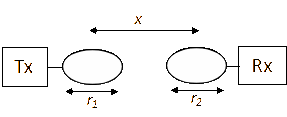
The capacity performance of a single input single output inductively coupled communication system was recently briefly discussed [3] and related to the Q-factors of the inductors in the application. The block diagram of a single input single output magnetically inductive communication system is shown in Figure 1. The transmitter and receiver are two parallel coils centered on a single axis. The two coils each of radius r1 and r2 are separated from each other by a distance x. The communications link between them consists of an inductive coupling k. The equivalent circuit model of the communication system is a lump circuit as in Figure 3. The coupling between the two magnetic antennas in free space can be estimated using the equation:
![Equivalent circuit of a pair of antennas [3].](/journals/journal-of-battlefield-technology/volume-13/issue-01/assets/13-1-4-agbinya/figures/figure03.gif)
M is the mutual coupling between the two inductive circuits and L1 and L2 are the inductive values of the transmitter and receiver coils respectively.
The received power and the coupling coefficient as a function of distance between the two coils can be estimated from Figure 1 and Figure 3.
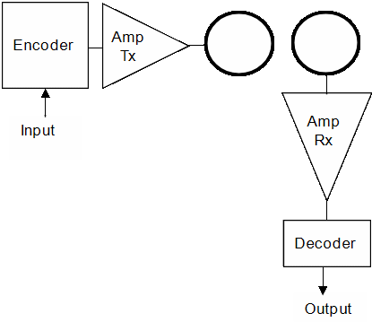
Figure 2 illustrates the implementation of the system.
From Figure 3, a relationship can be established for the currents flowing in the transmitter and the inductive current in the receiver. Let and:
The reactive power from the source coil is given by:
The efficiencies of the coils describe how effective they are in transferring power and by definition:
The quality factors are also given by definition to be:
The power delivered to the receiver load is given by the expression:
where:
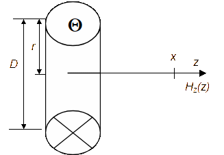
We can also give an equation of the receive power in terms of the magnetic field at x. The magnetic field at point x along the axis of a single turn coil of diameter D = 2r (Figure 4) carrying a peak phasor current is given by the expression:
The reactive power density is also given by the expression:
Therefore:
The coupling coefficient k(x) between the transmitter and receiver as a function of distance provides an estimate of the energy transfer at each point along the separation line between the transmitter and receiver. This is derived with a few approximations by using the expression for the coupling volume of a single receiving turn coil which is:
In this expression, A is the area of the coil that collects some of the magnetic flux created by the source and L is the self-inductance of the coil.
To derive k(x) we need to illustrate the physical arrangements and show distances and the engaging magnetic fields as in Figure 4.
The volume density is the ratio of the reactive power flowing in the transmitter to the reactive power density per unit volume created at the receiver site by the transmitter.
Therefore, the coupling coefficient as a function of distance k(x) is:
The self inductances themselves can be estimated with the expressions when N=1:
We make one more approximation. We assume that the radius of the coil is far less than its length or . Hence for N=1:
Finally, we obtain the expression for the coupling coefficient to be:
Of course, we can also write k(x) as:
If , k(x) does not account for the thickness of the wires and used in coils at the transmitter and receiver. When their thicknesses are taken into account:
The coupling coefficient is modified accordingly to be:
Bubble factor concept and characteristics
NFMI communication is promising in its ability to create a so-called secure communication ‘bubble’. However, current literature provides little information about the characteristics, size and extent of the magnetic bubble. By inference, most authors appear to assume that the size of the NFMI bubble is the same as the edge of near field. The two are not identical. The signal level at the near field edge is however still too high and easily available for interception. In this section we define the size of the magnetic communication bubble.
Size of nfmi bubble
Intuitively, we define the magnetic bubble in terms of the sensitivity of the receiver. Let d be the distance at which the received signal power is equal to the sensitivity of the receiver , where is the sensitivity of the receiver. The size of the magnetic bubble is defined as the distance d where the received power is just equal to the sensitivity of the receiver. With this definition, the size or the extent of the bubble is not fixed—but rather a function of the capability of the receiver. If the receiver is highly sensitive, the bubble it sees has a large radius. We may also define the size of the bubble in terms of the signal-to-noise ratio (SNR) of the system. With this abstraction, we define the radius of the magnetic bubble as the distance where the received signal power is just equal to the noise power ( or SNR=1. Therefore the system capacity at the edge of the NFMI bubble is given by:
At the edge of the bubble, no signal amplification will help in detecting the signal because noise is also amplified equivalently—so the bubble remains secure and silent to someone outside it. The 3-dB fractional bandwidth B is defined purely by the Q of the coils and the centre frequency, where:
By letting , this expression reduces to and the capacity at the edge of the bubble is:
This is determined exclusively by the Q-factors of the coils and the resonance centre frequency. For a resonance frequency of 13.56 MHz and Q=40, this capacity is approximately 218 kbps. The capacity at the edge of the bubble is directly proportional to the resonant frequency. The higher Q is, the lower the capacity at the edge of the bubble. Therefore a high transmitting Q or a high receiving Q do not automatically lead to high capacity. This paradox is the major benefit of NFMI.
In a nutshell, in this section we have demonstrated that it is clearly possible to model and quantify a NFMI system using its parameters. The physical attributes of the transmitter and receiver (radius, length, Q-factor, efficiency, etc) directly provide an estimate of the received power at a distance x from transmitter. The capacity and performance of a NFMI communication system can thus be quantified. The next section uses these results to define and estimate the system bubble factors.
Nfmi bubble factors
From the equivalent circuit model of Figure 3, the following relationship is known for the coils at resonance:
The two coils are chosen so that they resonate at the same frequency and permit communication to be established between them.
The advantage of NFMI communication is its ability to create a so-called secure communication ‘bubble’ around the source. Its performance should first be evaluated in terms of the efficiency of the communication bubble. We therefore propose a new metric for assessing NFMI communications called the ‘bubble factor’. Three bubble factors are used to assess how well the transmitter keeps its communications within a required bubble size or the so-called ‘cone of silence’. Outside the cone of silence, the available signal power is too small to be detected at close range. The three bubble factors—distance, resonance and receiver load—estimate the level of inherent security and the degree of difficulty for intercepting a communication using near field magnetic induction. The power transferred to the receiver load resistance RL in NFMI communication (Figure 3) is proportional to the transmitted power, the quality factors of the coils, the coil efficiencies and the coupling coefficient. When the radius of the transmitting coil is far smaller than the distance of coverage, we can approximate the received power at x by the expression:
From this expression, we observe that the received power at any point in space is a decreasing function of distance to power six—provided the radius of the transmitting coil is far smaller than the distance at which power is measured away from it. We define the decaying power distance bubble factor for near-field magnetic induction communications as:
Let and . The received power decays by −60.25 dB for the first metre of range and after that by the sixth power of range.
We define a second bubble factor, the resonance bubble factor , by substituting for Q. Coupling of energy to the receiver is optimum at the resonant frequency. Hence the performance of the system as a function of the resonant frequency of the transmitting and receiving coils is of interest. From (4) and (5) and Figure 3, we can show that the received power is:
With inductive resistances of 20 Ω each, ,, and load resistance of 1 kΩ, the transmitted power has decayed by 162 dB at 1 m at resonance. Received signal power at any distance is high if the resonant frequency is high. Hence for small magnetic ‘bubble’ communications, coils with small radii, small efficiencies, low inductances, high source resistance and high load resistance provide small bubbles.
A third bubble factor, the receiver load bubble factor, is also defined. This is obtained when the load resistance in the receiver is much greater than the self resistance of receiver inductor as:
The receiver load bubble factor shows that high source and load resistances create small bubbles. So, when an interceptor tries to maximise reception by increasing the receiver load resistance, no advantages are gained. The expression also shows that the communication system can be made directly proportional to the resonant frequency and distance by equating the receiver load bubble factor to the receiver resistance or set:
This is an essential system design parameter for near-field communication transceivers.
Conclusion
This paper has presented essential properties and definitions for, and an analysis of the extent of, the NFMI communication bubble. It shows that by defining the edge of the bubble in terms of the signal-to-noise ratio, we can better understand the security of the communication. We have also derived expressions for the coupling coefficients in NFMI communication with coils of different radii. The received power was also estimated. This was used to quantify the defined bubble factors. Three bubble factors measure the performance with distance, at resonance and with the receiver loads and provide efficient performance measures for near field communications systems using magnetic induction. This is essential for data transfer between magnetic devices at very short ranges and also for voice communications where the objective is to limit voice leakage between neighbouring receivers.
References
[1] C. Evans-Pughe, “Close encounters of the magnetic kind”, IEE Review, May 2005, pp. 38–42.
[2] R. Bansal, “Near Field Magnetic Communications”, IEEE Antennas and Propagation Magazine, Vol. 46, No. 2, April 2004, pp. 114−115.
[3] H. Jiang and Y. Wang, “Capacity Performance of an Inductively Coupled Near Field Communication System”, Proc. IEEE International Symposium of Antenna and Propagation Society, 5–11 July 2008, pp. 1-4.