
Volume 12, Number 3, November 2009
Architecture Practice Supporting Connectivity Analysis
- 1 Meredith Hue, Defence Science Technology Organisation, Land Operations Division, BLG 75, P.O. Box 1500, EDINBURGH, S.A. 5111.
Abstract
Insight is provided into architecture practice supporting development of deployed communications and information system (CIS) capability in the context of Network Centric Warfare (NCW). In determining what NCW capability may be extant in various instantiations of a force, and at different epochs, an important starting point is to understand what connectivity can be supported. An NCW intra-nodal technical reference model and a set of simplified architecture descriptions are outlined to support analysis of connectivity between disparate nodes in a heterogeneous networking environment. The approach to connectivity analysis is drawn from graph theory, which allows the force to be represented in simplistic terms as a set of graph nodes and links supporting different types of information transfer. This is then related to the actual NCW infrastructure which is carrying the respective information flows. The methodology supports analysis of what platforms and organisations share the same communication bearers, the same networking environments, and the same computer-based applications, including consideration of protocols employed, traffic types supported, gateways provided, security services supported, and how many users/system and systems/user. The methodology was used to support connectivity analysis during a recent major military exercise in support of measuring NCW capability of a Networked Maritime Task Group.
Introduction
Architecting in Defence has risen to prominence to provide mechanisms to assist implementation of Australian Network Centric Warfare (NCW) Capability and its underpinning Information Capability. NCW is a warfighting concept, described as a means of organising a force by using modern information technology to link sensors, decision makers and weapons systems to help people work more effectively together to achieve the commander’s intent.[1] The notions of NCW and the seamless integrated Force are demanding unprecedented coupling between previously disparate capabilities and organisations, resulting in a massive expansion in information exchange requirements and underlying connectivity requirements compared to the pre-NCW era. Implementation of Information Capability in the form of a Defence Information Environment (DIE), underpinning both NCW warfighting and corporate business, presents significant challenge to Defence as it seeks to transition from a legacy aggregation of disparate independent stove-pipe information systems to a deliberately planned emerging architecture which has a specific topology with much greater cohesion than its legacy predecessors. This means greater account is needed of the relationships between the respective systems and equipments to support the increased connectivity requirements, and greater account of the underlying detail of the infrastructure providing this connectivity.
Since much of the legacy documentation is systems engineering based, technical information on NCW infrastructure is largely focused at individual system, sub-system or equipment level, and is agnostic to the larger System-of-Systems (SoS) NCW context. There is a paucity of technical representation of Capability infrastructure at the SoS level in the NCW context and little guidance is available on how to provide such representations. It thus presents significant challenge to convey the concept of the emerging structure and to promulgate the necessary technical information to accomplish the desired transition. An NCW Intra-nodal technical reference model (TRM) and a set of simplified architecture descriptions are outlined to aid connectivity analysis of NCW related infrastructure. Interface compatibility and performance can thus be examined for different instantiations of the networked Force to establish if the extant or proposed NCW infrastructure can support the required information environment. The method for describing the infrastructure incorporates both legacy and future possible representations, and reveals the key electrical interfaces, technical standards and system relationships shaping the emerging structure towards a more seamless and integrated force.
Current architecture approach
Defence is implementing an enterprise architectural approach, mandating the use of the Defence Architecture Framework (DAF) for those major capital acquisition projects acquiring information-related capability [3]. Architectures are seen to provide a common approach to ensure SoS or enterprise-wide characteristics can be achieved across the evolution phases of individual systems that are being built in conformance with the architecture, where individual systems interconnecting into a larger distributed SoS are being progressively upgraded over time [4]. However, individual Defence projects are responsible for systems engineering and architecting activity for only those systems within their own project purview. Projects therefore have distributed responsibility for achieving SoS and enterprise-wide architectural coherence. The approach is thus heavily reliant on the mandating of enterprise-wide standards towards achieving significant increased homogeneity across the enterprise, and synchronising the transition of standards within individual system upgrades towards common standards to maintain architectural coherence; seeking to reduce the need for discrete engineering of individual disparate system interfaces.
Towards this end, initial efforts have been directed towards developing the respective Defence Restricted and other classified network domains comprising the Defence Wide Area Communications Network (DWACN) within the DIE, significantly improving network connectivity between users in the fixed environment. However the deployed environment differs significantly from the fixed environment; it is principally heterogeneous in nature, it needs to satisfy a huge array of different and changing operational needs compared to the fixed environment, and incorporates a plethora of different legacy systems and interface standards yet to be reconciled. Therefore there is still a substantial need to explicitly identify individual key system interfaces and associated technical characteristics in the deployed environment, at least some extent, in order to plan and manage the orderly transition from legacy systems to future deliberately planned SoS architectures towards achieving the aspirational seamless integrated Force.
Daf architecture view limitations
The primary vehicle for managing the DIE is the DIE Strategic Planning Framework, which provides a TRM for the DIE as shown in Figure 1. [5]
![Defence Information Environment representation. [5]](/journals/journal-of-battlefield-technology/volume-12/issue-03/assets/12-3-3-hue/figures/figure01.gif)
The DIE TRM articulates the Defence Information Infrastructure (DII) as a discrete entity within the DIE, spanning both the fixed and deployed environments, including bearers, networks, system hardware, user devices, user applications, data, and common services. The main focus for current Defence architecture practice is on production of DAF-specified operational, system and technical architecture descriptions to describe aspects of the DII from different perspectives. Technical information on the infrastructure is provided in the system and technical views. Since DAF views are prepared by projects, they provide a project-centric perspective.
DAF views typically only provide limited technical detail on both internal and external system interfaces in the architecture products prepared by the respective projects. Of note, the primary purpose of these views is to support an investment decision making process, rather than to support a systems engineering process. As such, system views typically convey abstract or conceptual notions rather than providing any detailed account of actual system components and interfaces, either of extant infrastructure or envisaged new infrastructure. With a reliance on lists in technical views quoting general enterprise standards (that is, “internet” style approach”), there is less emphasis on explicitly identifying individual system interfaces, lacking the detail necessary to engineer individual system interfaces to achieve the desired level of SoS integration.
Currently, there is no explicit guidance provided to projects relating the use of TRMs such as the DII during the development of DAF architectural descriptions. Information content in the architecture descriptions is thus discretionary within project boundaries, with no mandate for ensuring consistency and compatibility of architectural information across project boundaries during successive iterations of NCW-related infrastructure. In the absence of a meta-data model, considerable discretion is provided to individual projects on information content within the products, and the level of detail proved therein. This means different descriptions can be provided of the same interface from each adjoining system. This inconsistency in representation means it can be challenging to relate or re-use DAF architecture products across project boundaries to develop a SoS perspective. This is compared to systems engineering documentation, where specific data item descriptions can prescribe considerable detail to ensure interface compatibility is maintained across multiple interface boundaries. Thus there is significant reliance by individual projects on the enterprise guidance to achieve and maintain architectural coherence across project boundaries.
The lack of consistency in technical detail across project boundaries can hinder the promulgation of standards across project technical architectures for infrastructure planning, contraindicating the wider SoS architectural coherence sought. The view-based approach of the DAF and its project specific application thus constrain the extent to which cross-project interfaces can be examined for architectural coherence.
Formalising content in some architecture products, particularly relating to infrastructure descriptions could ostensibly improve consistency and quality of information in architectural products across project boundaries. However, it remains to be determined whether a common approach might be feasible, with the appropriate fidelity, accounting for all respective platforms, nodes, links, services, C2, sensors and weapons, and providing sufficient common and consistent technical information to realise the wider SoS architectural cohesion sought. Further insight into NCW Capability is needed to determine what guidance might be useful to systematically describe NCW related infrastructure and services that will expose the required technical detail in a structured way.
The NCW context
The Network Dimension is a central theme in the NCW Concept [1], where the notion of linking sensors, C2, effectors via the Information Network is succinctly portrayed in the NCW Roadmap as shown in Figure 2. [8] This means the sensors, C2 systems, people and weapons encapsulated within the NCW paradigm are linked together via communications and information system (CIS) infrastructure to provide the required connectivity. In practice, some CIS infrastructure may also be required to support non-warfighting information flows. It behoves therefore to include both warfighting and non-warfighting functionality in consideration of the implications for the CIS infrastructure, spanning both the fixed and deployed operating environments.
![Abstract representation of NCW grids. [8]](/journals/journal-of-battlefield-technology/volume-12/issue-03/assets/12-3-3-hue/figures/figure02.gif)
Connectivity analysis information needs
When undertaking connectivity analysis, typical information sought might include:
- Who needs to talk to whom? (Person/platform/role/system/equipment)
- What type of information is to be exchanged?
- How is the information to be exchanged? For example:
- Information applications.
- Message types.
- Data formats.
- Network protocols.
- Communication bearers.
- What common services need to be provided? For example: security, network management, policy controls.
- What are the physical characteristics?
- What are the electrical characteristics?
The DIE TRM incorporates many of these network infrastructure considerations in its representation of the DII. Of note, this information is abstracted from the end user and the operational context. It is also agnostic to the systems and interfaces supporting the information flows. The NCW context is supported to the extent that sensors and weapons (or effectors) are identified as separate conceptual entities to the DIE, but no guidance is provided in the system context as to where system boundaries and systems interfaces might manifest.
To be able to address these questions on connectivity, it would be useful to be able to identify participating nodes and links and associated underlying information infrastructure providing connectivity for different information types and information flows relating to the NCW constructs. A means is therefore needed to describe the sensor, C2, network (ICT) and effector functionality associated with NCW Capability in a way that will allow ready identification of these key interfaces, and information flows supportable across these interfaces.
Making sense of NCW nodes and links
In NCW parlance, frequent mention is made of nodes in a network communicating via links. But what does this mean and how is it helpful?
The concept of nodes and links emanates from graph theory, which provides a formal definition of a network. A graph is a collection of points called nodes. Some of the points in the graph can be joined by lines called arcs or branches. A path between two nodes in a graph is an ordered set of arcs. A graph is said to be connected if there is a path joining any two nodes of the graph. [9]. An arc of a graph is directed if there is a sense of direction so that one node is considered the point of origin and another node is the point of termination, A network in this context is an interconnection of several nodes in the graph by routes between certain pairs of nodes. Each route has capacity, and amounts of “material” can be moved or flowed along the routes between the nodes.
From this perspective, the NCW Information Network can be regarded as a collection of nodes with linkages between nodes such that information can flow between the nodes across the linkages, as shown in Figure 3.
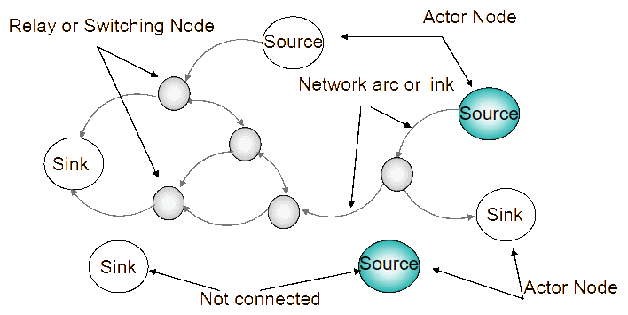
No pre-determined pattern of linkages is implied in the network. A node can be part of the collection, but have no direct linkages associated with it as shown in Figure 3.
In this context, nodes can:
- source information (that is, create information);
- sink information (that is, store and/or use information); and
- switch or relay information (that is, neither create nor use nor store information, but can provide a pathway or gateway to pass information through from source to sink).
Thus two types of NCW infrastructure nodes can be differentiated in the Information Network:
- those information infrastructure nodes that can source, store or sink information (that is, actor nodes), and
- network/communications infrastructure nodes that provide switching and routing of information, where information is neither created, nor used, nor stored (that is, relay/switching nodes).
The linkages between the nodes are provided by the network/communications infrastructure.
Nodes and linkages can then be grouped or categorised in different ways to express different concepts associated with the Information Network.
In the NCW context, this means that:
- Decision makers can be represented as actor nodes that create, store and or/use C2 related information.
- Sensors can be represented as actor nodes that create, store, and/or use sensor information.
- Effectors can be represented as actor nodes that create, store, and/or use effector related information.
The Information Network can therefore be represented as the collection of all C2, Sensor, and Effector actors together with the network/communications infrastructure relay/switch nodes and linkages within the NCW infrastructure, as shown in Figure 4.
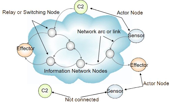
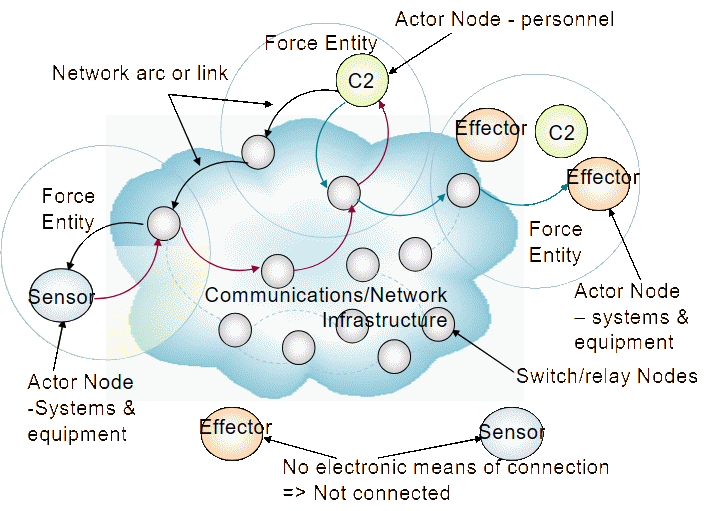
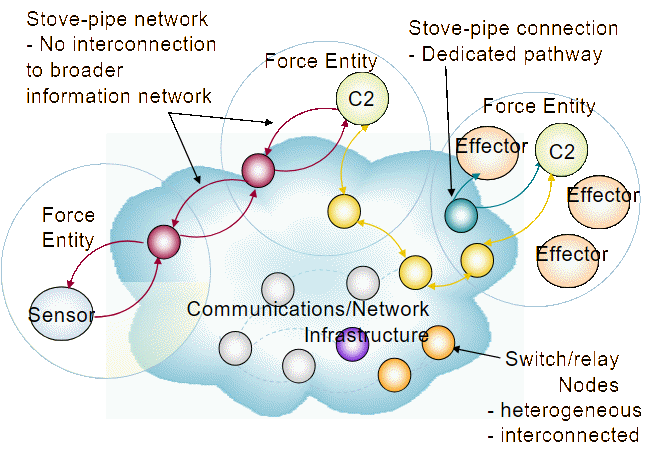
Ostensibly, the actors in the Information Network will be platforms, systems, applications and/or people who either create, use or store information. These may or may not have either physical or electronic connection with other nodes. In this context, face-to-face interaction using voice (that is, voice primary) can be considered as a physical interaction which supports an operational information flow without any electronic connection. Since the linkages between the nodes are provided by information infrastructure, actors using face-to-face voice communications will not be connected using this representation as the information exchange did not take place over an electronic connection, whereas voice over radio would be shown as being provided by an electronic connection. This means an actor is connected to the information network only if it can support electronic exchange of information over the information infrastructure to another actor i.e. information is transferred from source to sink electronically as shown in Figure 5. Information transferred from source to sink can traverse multiple interconnected communications/network infrastructure nodes and links, where the end-to-end performance of the network connection will vary depending on the characteristics of each link in the connection. In real terms the Information Network underpinning NCW capability is not homogenous in nature as shown in Figure 5, but is an aggregation of stand-alone and interconnecting networks, with potentially significantly differing characteristics, as shown in Figure 6.
Representing NCW infrastructure in the sos context
Whilst it can be useful to describe the Information Network in terms of nodes and links, further detail is needed to expose the external interfaces at individual system boundaries to support connectivity analysis. However, delineation of any particular system boundary within a larger SoS is context dependent, and can appear quite arbitrary unless the decision criteria for partitioning or system aggregation is clearly articulated. This allows considerable latitude in setting down criteria to identify key internal and external interfaces in NCW-related infrastructure.
Since DIE guidance is only applicable to the CIS infrastructure, other systems generating or using information will present external interfaces to the CIS infrastructure. The NCW related infrastructure for a platform or organisation can thus be represented as described in Figure 7, where the sensor and effector infrastructure present specific external interfaces to the DIE CIS infrastructure, consistent with the notion of NCW nodes and links as described in Figure 6.
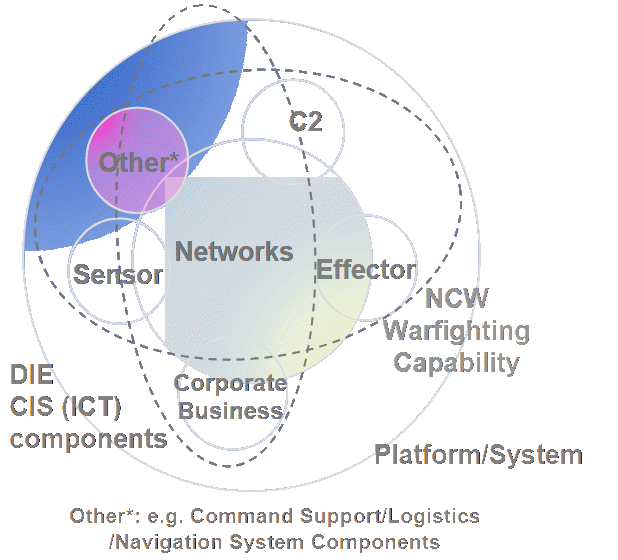
Representing the network dimension
While the representations of Figures 6 and 7 can be useful in identifying key external interfaces to platforms and organisations, greater fidelity is needed to identify key sensor, effector and CIS interfaces which might be present within a platform or organisation since these may support key internal information flows between discrete systems. To undertake connectivity analysis, it is necessary to distinguish between NCW infrastructure which is generating, storing or using information (that is, actor nodes), and that which is only acting to distribute the information (that is, relay nodes and links). While TRM such as the OSI Reference Model [10] can be useful to identify the complete set of interface protocols within a system, in practice, it is not used as criteria for system partitioning into sub-systems and components. It is therefore not helpful to use the OSI Reference Model as a method for identifying CIS interfaces between NCW infrastructure. However, all CIS related configuration items (CI) which can be procured separately, whether they might be software or hardware CI, will present interfaces within the larger system in which they reside. As such, they may require accounting for within the NCW-related infrastructure if they directly contribute to the carrying of key information flows across system boundaries and therefore are part of the aggregate SoS architecture.
A representation can thus be built up of the entire Network Dimension as described in Figure 8, which encompasses all functionality supported by the NCW infrastructure within the auspices of the Information Network, including identification of specific CIS applications, their host platforms, interconnecting communications and networking infrastructure, and the relevant external and internal system interfaces. Since many supporting standards and protocols are service based, they can be pervasive across the respective information systems and communications infrastructure, and must be explicitly identified using domain specific TRM to provide further elaboration. Thus hardware, software, middleware, and operating system interfaces can be accounted for should they be relevant.
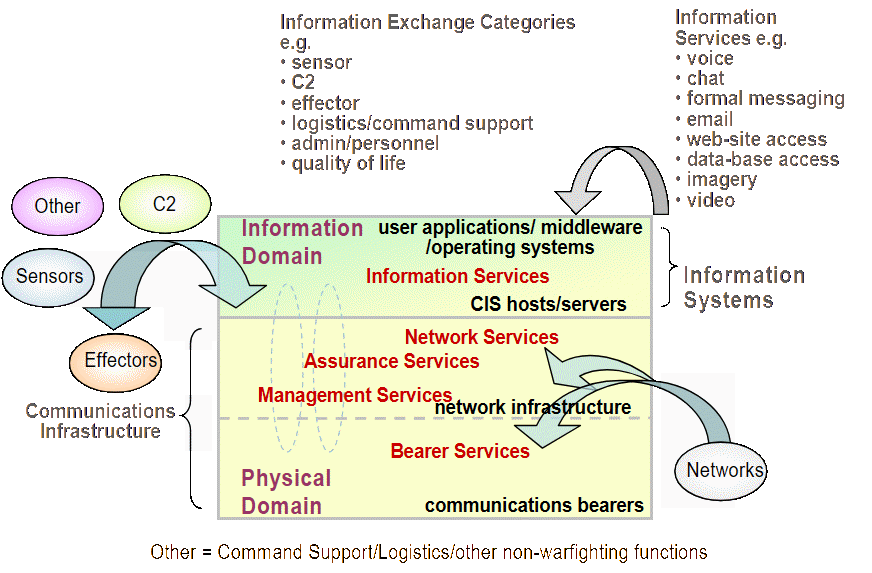
Of note, while the notions of the Sensor, Command and Control (C2), and Engagement Grids and the underpinning Information Network are pervasive through Australian Defence NCW literature, these are abstract concepts, with no commonly agreed definition or articulation. While this articulation may be a useful aid at the conceptual level, it has not been leveraged in architecture practice thus far by the projects. The representation of the Network Dimension therefore does not seek to portray any representations relating to the notions of the NCW Grids.
Representing NCW infrastructure in the system context
The concept can then be extended to each platform or organisation to identify the relevant key internal and external system interfaces contributing to NCW functionality. It is important to incorporate notions of both internal and external information flows so that system boundaries can remain notional, allowing the fidelity of representation to be tailored to the particular problem at hand whilst preserving the integrity of the interfaces.
An important differentiation is made between infrastructure which has a human-machine-interface (HMI) compared to infrastructure which has not. Here, for example, if a sensor system has a HMI in addition to the actual sensor, then the representation should identify the internal interface between that part of the system which provides the HMI functionality and that which provides the electrical/electronic sensing functionality. Importantly, the concept can be extended beyond network interfaces to include electronic buses and other electrical connections such as power supplies, allowing both electrical, electronic and network interfaces between different NCW infrastructure to be captured as well as all relevant user interfaces. An Intra-nodal TRM of a notional system (either a platform or an organisation) can be thus constructed as shown in Figure 9, which allows identification of both internal and external interfaces and their respective standards, based on ascribed NCW functionality.
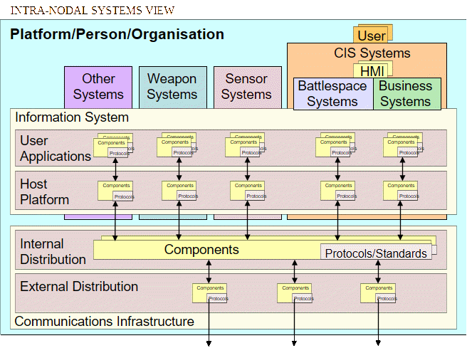
The TRM draws distinction between infrastructure which supports information flows from computer-to-computer (machine-to-machine), and infrastructure which provides a HMI. By definition in this reference model, any HMI is designated as CIS infrastructure since it is providing an information service by either providing information to a human operator or accepting information from a human operator. Thus C2 infrastructure, by its nature, is therefore classed as CIS infrastructure since it presents a HMI to the decision maker, whereas weapon and sensor infrastructure (excluding the HMI) are not. The HMI are specifically excluded from the sensor and weapon systems since by definition any sensor or weapon system HMI is classed as CIS infrastructure. This CIS infrastructure then presents an interface (either internal or external) to the electronic sensor or weapon system infrastructure that is performing the sensing or effector functionality. This is to accommodate circumstances where the same infrastructure may support multiple types of information flows which do not have clear delineation between source, store, and sink functionality.
The NCW Intra-nodal TRM also recognises that not all information systems are directly related to the sense, decide and effect functionality underpinning the NCW concept, such as business management systems and maintenance systems. Logistics information can be ascribed to the CIS infrastructure within this construct as well as administration and quality of life (described as “other”); thereby accommodating both battlespace and business applications that may share the same underlying networks and communications infrastructure. Thus for each type of information flow, whether it be computer to computer or human-to-machine, applying the formalisms of the NCW Intra-nodal TRM facilitates the characterisation of the military information environment, both in the business and the battlespace context, in terms of the user applications and host platform comprising the information system itself; the interface between the information system and the communications infrastructure; and the means by which the information is distributed internal and externally throughout the communications infrastructure. It also identifies key components and interfaces within the platform or organisational element, spanning hardware, software and middleware, exposing the requisite technical standards and protocols.
This TRM thus provides a structured approach to account for the information content in a number of DAF views including:
- SV1: System Interface Description
- SV2: System Communications Description
- SV3: Systems Matrix
- SV4: Systems Functionality Description
- SV6: Information Exchange Matrix
- SV7: System Performance Parameters Matrix
- SV8: System Evolution Description
- SV9: System Technology Forecast
- SV11: Physical Data Model
- TV1: Technical Architecture Profile
- TV2: Standards Technology Forecast
Note that infrastructure can also be grouped according to security domain, thus allowing security considerations to be incorporated. Critically, this representation is independent of information content, and can therefore be scenario independent. However, it may be useful to overlay a particular operational context to bound the scope of the SoS under consideration for the particular problem at hand, and to determine the appropriate fidelity of representation.
It can thus be used to answer key questions for any particular system or SoS infrastructure in use or proposed to support delivery of information exchange requirements (IERs), such as:
- What data or information can be exchanged between different platforms/organisations?
- What equipments, hardware devices and user applications are supporting the information exchange?
- What information distribution mechanisms are available?
- What communications bearers are available?
- Where are interface boundaries located?
- What are the characteristics of the interfaces?
- What external bearers are shared by different platforms and organisations?
- What platforms/organisations share:
- The same information systems?
- The same networking environment?
- The same external communications bearers?
- What applications can share the same information between different platforms/organisations?
- What gateways are provided, where they are located, who has access, and what information can be passed through?
- What protocols are supported?
- What traffic types are supported?
- What common services are supported?
- What security services are supported?
- Which users have access to which information?
- How many users/system or HMI?
- How many systems or HMI/user?
- What traffic flows are supported?
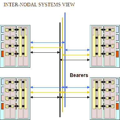
- An example of use of the NCW Intra-nodal TRM is shown in Figure 10 to present a communications bearer connectivity perspective between different platforms.
The technical standards at the interface boundaries for the respective information services thus become evident as shown in Figure 11. Here for the example of uncovered voice, the information service is designated as “Plain Voice”. The information system shown supporting the delivery of the Plain Voice information service is a Voice-Over-Internet Protocol (VoIP) telephone. This supports associated communications technical standards and network protocols such as G.728A, RTP, UDP and IP. Since it is connected to an IP router via an Ethernet connection, the associated local distribution infrastructure supports technical standards and protocols including Ethernet and 10BaseT. The output from the router to the modem is connected via RS-422 interface standard. The output form the modem has a technical standard associated with the modulated waveform in the allocated RF band. Thus all relevant internal and external interfaces and their associated technical standards are revealed in the platforms that require specific interface engineering to achieve end-to-end connectivity.
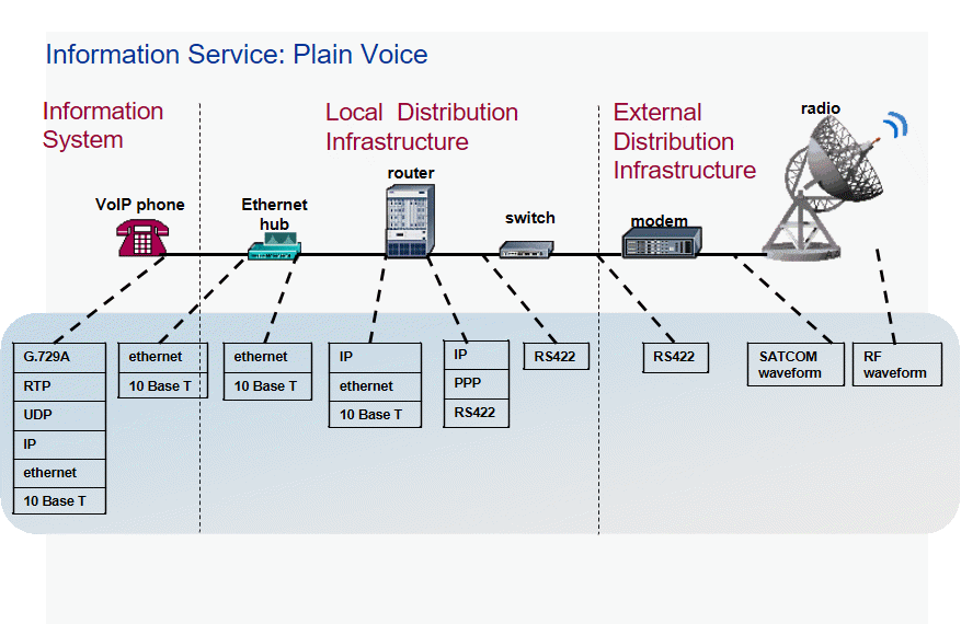
The formalisms within the NCW Intra-nodal TRM of Figure 9 supplement the DIE TRM of Figure 1 by providing additional depth of information relating to the technical interfaces to assist in the engineering of NCW related interfaces. The DIE TRM does not provide a means to explicitly correlate the multitude of Defence NCW-related systems and their interfaces with specific standards. The NCW Intra-nodal TRM assists by providing the required attributions between the respective system internal and external interfaces and their associated standards to support engineering the interfaces associated with the provision of NCW-related functionality. The formalisms thus expose the necessary information to be able to analyse connectivity for both extant and proposed new NCW infrastructure, and provide additional rigour to the respective DAF system and technical views of the Systems and SoS concerned to determine whether the aspired level of interface compatibility and integration can be achieved from a technical point of view. Using the NCW Intra-nodal TRM to reveal key interface details should therefore assist with the interface design and integration of new and evolved NCW-related systems as they are progressively brought into service towards achieving key interface compatibility.
Case study: the maritime environment
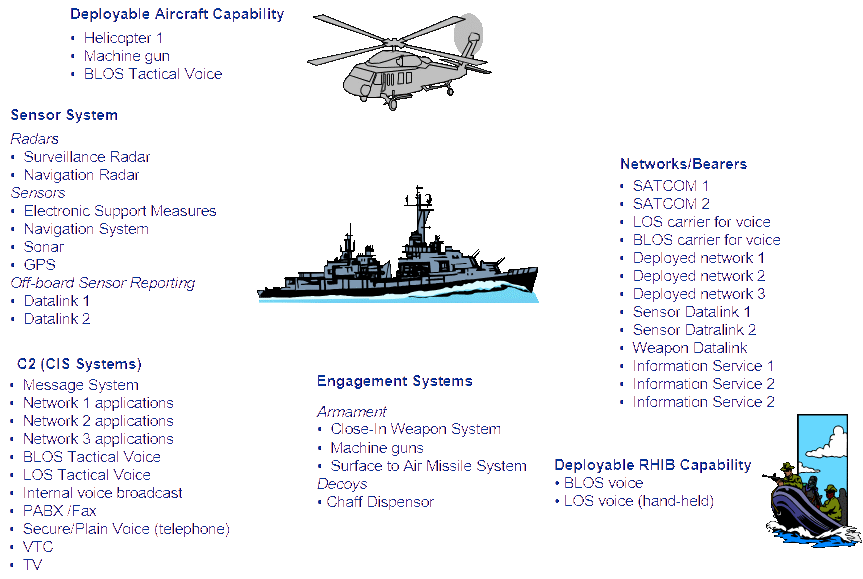
The formalisms and methodology described above were used during a recent military exercise to examine the ability of the infrastructure in the maritime environment to deliver the required information. C2, sensor, effector and communications/network descriptions were prepared for different classes of platform and for different platform configurations as shown in Figure 12, including associated organic assets. All electronic systems for each class of platform were catalogued according to whether they supported C2, sensors, effector or network/communications functionality, together with the associated interface protocols and technical standards. Ships navigation, sonar and radar capability were explicitly identified as sensor infrastructure; data links connecting sensors together were designated as networks/communications infrastructure; and ships weapon systems and decoys were designated as effectors. Software applications hosted on various networks were also itemised, as were the networks themselves for each class of ship. A SoS perspective across the maritime environment was developed from this information set as described in Figures 13 and 14 where Figure 13 provides a mapping of information services from an individual communications bearer basis, while Figure 14 provides an aggregate perspective for all communication bearers for the various classes of platforms and different platform configurations within the same class. It was thus immediately evident whether different types of information could be disseminated to different class of platforms and different platform configurations within the maritime environment.
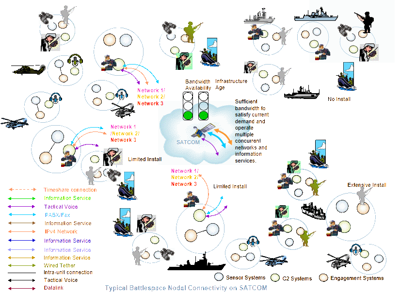
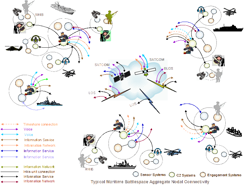
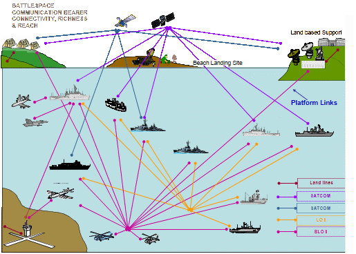
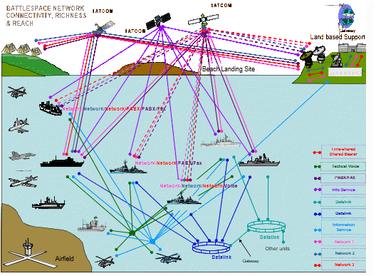
All classes of platform within the SoS of interest were represented in DAF OV1 style high level operational concept graphics as shown in Figures 15 and 16, where Figure 15 illustrates the connectivity provided by the communications bearers where platforms have been abstracted as network nodes, while Figure 16 illustrates connectivity supported at the information service level.
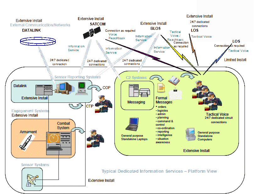
Each platform was examined from a systems perspective, with key internal sub-system boundaries between sensors, effectors, C2 and network/communications infrastructure represented using a DAF SV2 style product as shown in Figure 17. It was therefore possible to determine what sensors were fitted within each platform; where the sensor information was distributed within the platform; who had access to this information, what C2 systems were fitted, what effectors were fitted, and thus how information was being distributed from sensor to decision maker to shooter. It also revealed where the information stove-pipes were, and where disconnects were evident within the platform. Disconnects between platforms were also revealed by comparing external interfaces between different platforms classes and platform configurations, with the disparity in interface standards exposed.
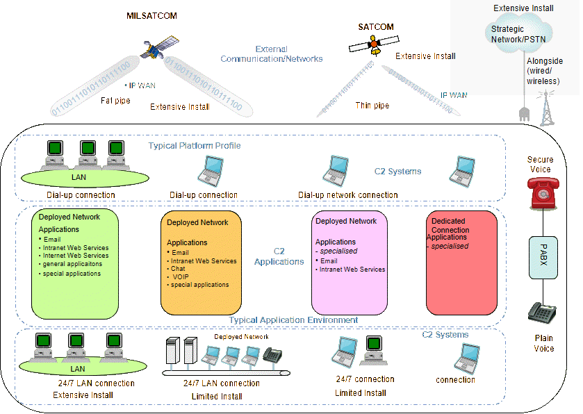
A detailed representation of the CIS environment internal to the platform was also developed as described in Figure 18, including representing different security domains. Thus all systems, sub-systems, equipments, and software were accounted for, together with all key internal and external interfaces in the NCW SoS context. All of the information encapsulated in Figures 13 through 18 was derived from the information compiled through an initial audit of the platform capabilities as represented in Figure 12, with the requisite detail as described in Figure 11 for each information service. This detailed representation of the maritime information environment provided the basis for the subsequent analysis which examined the adequacy of the connectivity supported for various installation configurations in an operational context.
Conclusion
An NCW Intra-nodal TRM and a methodology for representing different DAF views have been described to assist identification and promulgation of key information relating to NCW Capability to support architecture analysis incorporating connectivity analysis. It provides a means to provide a comprehensive representation of sensors, C2 systems and effector infrastructure, together with the underlying communications networks supporting the NCW Concept that can reside in an information repository subject to configuration control. This information can also provide a basis for modeling and simulation of infrastructure for performance evaluation.
It supports a SoS approach to architecture analysis that:
- is enterprise-wide
- is based on a common information set,
- is independent of individual major acquisition projects,
- is independent of context specific scenarios,
- supports multiple security domains, and
- is scalable from small scale to large scale system representation.
- Importantly, the use of the NCW Intra-nodal TRM in generation of DAF system and technical views supports preservation of information integrity across system boundaries, regardless of where boundaries are ascribed, which should assist in the quest for the seamless integrated Force. Since the methodology focuses on technical compatibility, it does not seek to address other aspects such as process integration, nor information management. However, technical compatibility is a critical pre-requisite within the larger problem of improving interoperability across the military environment and beyond.
- The TRM and methodology for representing different DAF views have been successfully applied to a number of classes of platforms in the maritime environment as a prelude to evaluating its ability to support the required information flows. Attention is now being directed to assess the potential of architecture tools to utilise the NCW Intra-nodal TRM on a larger scale in support of SoS architecture analysis.
References
[1] Director General Capability and Plans, Explaining NCW, Defence Publishing Service, Department of Defence, Canberra ACT, 2005.
[2] Chief of the Defence Force, Force 2020, ADDP-D.2, Defence Publishing Service, Department of Defence, Canberra ACT, 2002.
[3] Hue, M.A., “Architecture Practice in Defence—Realising the Seamless NCW Force”, System Engineering Society of Australia, Newsletter No. 47, October 2008, pp. 34−46.
[4] Levis, A.H. and Wagenhals, L.W., “C4ISR Architectures: 1 developing a Process for C4ISR Architecture Design”, Systems Engineering, Vol. 3, No. 4, pp. 225−247, 2000.
[5] Director Information Communications Technology Futures, Defence Information Environment Strategic Planning Framework, Information Strategies and Futures Branch, Department of Defence, Canberra ACT, 2007.
[6] Brochure No. 1, Introduction to Enterprise Architecture, Information Architecture and Management Branch, Chief Information Officer Group, Department of Defence, Canberra ACT, January 2005.
[7] Director Capability and Plans, Defence Capability Development Manual 2006, Defence Publishing Service, Department of Defence, Canberra ACT, 2006.
[8] Director General Capability and Plans, NCW Roadmap, Defence Publishing Service, Department of Defence, Canberra ACT, p. 6, 2007.
[9] Wilson, Robin J., Introduction to Graph Theory, Third Edition, Longman Scientific Technical, 1985.
[10] Information technology—Open Systems Interconnection—Basic Reference Model: The Basic Model, ISO/IEC 7498-1:1994, International Standards Organisation, 1994.