
Volume 12, Number 3, November 2009
Evaluation Of Defence Architectures In Support Of System Integration
- 1 Joint Operations Division, Defence Science and Technology Organisation, Department of Defence, Canberra ACT Australia, 2600.
Abstract
This paper outlines an integrated framework in support of a generic problem of system of systems (SoS) integration and illustrates an application of the framework formalisms to evaluate a large architecture comprising the Air Combat Capability (ACC) integrated into its command control communication computer intelligence surveillance and reconnaissance (C4ISR) SoS environment. The framework utilises the notion of synthesis of executable architectures from their static Department of Defense Architecture Framework (DoDAF) specifications and focuses on the information interoperability aspect of integration. The DoDAF architecture, obtained in the earlier studies, was found not being readily amendable to development of executable models and hence certain refinements are performed. An operational activity process capturing the missions carried out by an ACC together with its corresponding properties is extracted from the architecture and modelled as coloured Petri net (CPN). State space analysis is utilised to investigate the CPN model. All possible execution sequences are generated and investigated to verify the properties of interest. The approach of developing executable architectures of the existing, large, non-execution compliant architectures assists analysts and designers to evaluate rigorously and efficiently and to compare architecture designs.
Introduction
Capability system development, also referred to as the capability life cycle, is an essential process conducted by the Australian Defence Force in order to maintain its future strategic options, technological edge and compatibility with allies. The process consists of five iterative and overlapping phases: needs, requirements, acquisition, in-service, and disposal [6].
Contemporary warfighting concepts, such as joint, interagency and coalition operations, effects-based execution, network-centric operations, and operations other than war postulate that new capability systems are not considered and developed in isolation (a ‘stove pipe’) but are harmoniously integrated into the existing or future force structures. The process of systems integration is seen as an enduring process occurring essentially at every phase of the capability life cycle. Given the ever-increasing performance and effectiveness demands placed on warfighters, together with the assortment, size, and complexity of the hardware and software systems being employed, the capability integration process is exceedingly difficult to manage and to accomplish successfully.
In this article we explore modelling and analytical formalisms to address the capability integration issues. Our approach is captured in a model-based framework dealing with the generic problem of integrating a new system into SoS force structures. The framework utilises the notion of synthesis of executable architectures from their static descriptions and focuses on the information interoperability aspect of integration [11]. Components of the framework are applied to a combined Air Combat Capability (ACC) and C4ISR architecture obtained in the earlier studies to explain the concepts; and to illustrate how our framework can be utilised to evaluate large, existing, and non-execution compliant architectures.
This work originated as a part of a larger interoperability study into the integration of the Joint Strike Fighter (JSF) into Pacific Rim (PACRIM) coalition C4ISR systems [10]. The purpose of the study was to identify and describe any interoperability gaps and provide recommendations that may need to be addressed in the development of the ACC (JSF) to effectively interoperate with AS, US and other coalition C4ISR systems in a future PACRIM theatre of operations.
The use of architecture models in SoS integration has been investigated in [9,17,18]. Conceptual levels of information interoperability are discussed in [19]. Procedures of constructing a coloured Petri net (CPN) model from the set of DoDAF products are presented in [1,3]. In [15] additional DoDAF views are developed to facilitate construction of executable models to enable system evaluation at the operational level. Sensor-to-shooter studies [2,4] illustrate simulation based methodology to assess different system designs.
Conceptually, our work is aligned to the work conducted at the George Mason University [1]—in a sense that we are constructing a CPN [12] model of the architecture described by DoDAF [8] products. In our approach we implement DoDAF products in the system engineering (SE) tool CORE [14] and then, using a CORE schema and the purpose-built scripts automatically construct a partially completed CPN model [11]. This model is then manually completed by an analyst.
Here the approach is applied to an already existing, non-execution compliant, DoDAF architecture and thus the complete application of the framework is not feasible. Instead, we focus on illustrating how the existing architecture can be evaluated, and to this end we describe the synthesis of a CPN model from the existing architecture and investigate the scope of analysis of the data produced by that model.
The remaining part of this paper is organised as follows. Section 2 briefly reviews current approaches to architecture evaluation. Section 3 provides a description of our framework. Section 4 briefly discusses the DoDAF architecture model. Subsequently, in Section 5 an executable model of the architecture is presented. This model is then investigated to evaluate the architecture. The final section presents the conclusions.
Evaluation of defence architectures
Governments and defence organisations internationally acknowledge the need for more rigorous, holistic and cost effective approach to capability system development [6,13,18]. It has been recognised that an architectures-based approach is one possible avenue to address these requirements [18].
An architecture is a repository of knowledge in a sense that it describes the system components and the relationships between these components. An architecture allows examination of the entire system or a selection of its components at different levels of abstraction. Adopting a well-defined notation architecture can provide a formal description of a system, which can be reasoned about using various analytic techniques.
An architecture permits analysts to discover and address potential design or implementation problems in the early stages of the development process, hence reducing risk and cost of the development.
The use of architectures in a systematic fashion is governed by architecture frameworks [8,16]. In essence, a framework provides the rules, guidance, and product descriptions for developing and presenting architecture descriptions. The products describe operational, system and technical views of the system with the aim to provide a common baseline for understanding, comparing, and integrating architectures.
Defence departments in US, Australia, UK, Canada and New Zealand, among others, have recommended or mandated the use of architectures in the system design process. In order to facilitate this process several architecture frameworks, such as DoDAF, MoDAF, and DAF, have been proposed [8,16].
The increased focus on architectures has led to proliferation of architecture products being included in a vast assortment of documents produced by or for defence departments as part of their capability development processes.
While the use of architectures and the associated formalisms is encouraging, some serious issues are beginning to emerge [18]. In particular, there seems to be limited understanding of the architecture design process and specifically of what products need to be developed, why they are required, and how they are related. There is also a noticeable lack of a well-defined process, the corresponding methods, and the tools to evaluate adequately the design.
While progress is being made in all these areas, the true potential of architectures is still to be fully realised and, on a whole, the evaluation methods are still largely inadequate and misunderstood.
An architecture design evaluation commences with the development of a design representation (a model) which can be reasoned about. The model captures the properties (requirements) that the architecture needs to satisfy. These properties are typically concerned with functional behaviour and/or performance aspects of the design. Subsequently, the model is analysed to ascertain that the properties of interest are satisfied.
There are numerous modelling techniques in use—ranging from hand-drawn diagrams to more-sophisticated computer assisted tools. Principally, all these representations belong to one of the two categories: non-executable models, and executable models.
A non-executable model captures static view (or views) of architecture and can only be examined statically. The rigour of such examination varies and it can range from subject matter expert (SME) assessment to a computer-tool-assisted evaluation (such as enforcing syntax checks to require that each activity has inputs, outputs, resources, and control). Static evaluation is an important step in an evaluation process but in itself it is not sufficient. In fact, architectures are not fully validated until they are executed [7].
An executable model, when executed, captures evolution of events which take place when the architecture components interact with each other. In fact, being able to evaluate the design through examination of these interactions is the principal reason for construction of executable models.
An executable model is obtained by a further refinement of a non-executable model, and there should exist a well-defined mapping between the two models. Such mapping, among other things, ensures that the results obtained when analysing the data produced by an executable model are applicable to the original architecture design.
Framework
The framework connects aspects of problem formulation, development and analysis in an integrated manner; that is, starting from a problem description, a procedure is provided to rigorously formulate, develop, and analyse an integrated SoS structure. The framework follows a generic architecting process: architecture design, architecture products construction, executable models development and analysis [1]. In our case, these stages are articulated as:
1. Architecture design.
- Problem definition.
- Functional decomposition of the problem.
- IDEF0 diagram construction.
- Specification of rules and sequences.
2. Architecture products construction.
- CORE tool implementation (DoDAF architecture).
- Development of CORE schema.
3. Synthesis of executable model.
- XML output.
- XQuery script and translation technology.
- CPN model construction (automatic and manual).
4. Analysis of data produced by the executable model.
An outline of the framework together with a particular selection of methodologies and tools is depicted in Figure 1. A more-detailed description of the framework can be found in [11].
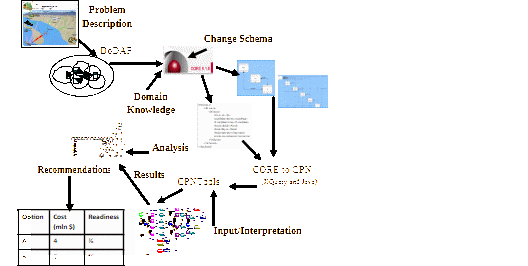
DoDAF architecture
The JSF study employed models extensively to define and understand SoS architectures [10]. A comprehensive model of the DoDAF architecture capturing the ACC and its C4ISR environment has been produced. The architecture is static and its main purpose is to describe and capture a collection of the requirements, system components and their relationships, all in one unified architectural framework. In what follows, we focus on the operational activity view of the architecture (called an OV-5 in DoDAF), which captures a high-level of abstraction description of operational activities (and indirectly, operational elements and information exchanges) required to accomplish ACC missions. This view is shown in Figure 2.
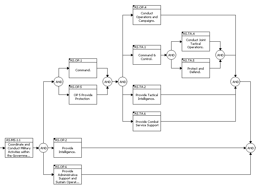
The model consists of one military strategy (MS) task, five operational (OP) tasks and five tactical (TA) tasks. All tasks, apart from MS task, expand to one more level of detail. All tasks are the Australian Joint Essential Tasks.
Briefly, MS1 generates goals and initiates the campaign. OP1 generates operational level plans, concepts and orders. OP5 provides protection of forces. OP2 provides intelligence during mission planning and execution. OP6 is the logistic support during mission planning and execution. OP4 is the operational level monitoring and dynamic retargeting. TA1 provides tactical mission planning and tactical mission command. TA2 provides tactical intelligence. TA4 corresponds to ACC tactical operations. TA5 supplies electromagnetic and acoustic jamming and TA6 provides technical and logistic support.
Based on the description of the process and the input provided by the SME the operational activity process exhibits the following properties of interest:
- MS1 has to occur first and only once during execution of the model.
- OP2 must occur before OP1.
- OP1 and OP5 must occur before any of the OP4, TA1, TA2, TA6, TA4, and TA5 can occur.
- System must not deadlock.
- All activities must have equal chance of occurring during execution.
In the remaining part of the paper the architecture of Figure 2 is evaluated to examine if it satisfies these properties.
Synthesis of executable model
The interoperability and future requirements analysis conducted by the JSF Study has been based on development and investigation of static architecture models [10]. Thus, it is important that the architecture models are correct and are valid representations of the systems being integrated. The development and investigation of the executable models of architectures ensures that the final product design meets the required specifications. Executable models allow operational logic and behaviour of architectures to be examined in time and space, hence assisting in validating if the rules are consistent and complete and if the architecture does what is intended to achieve [1,3,13].
Often, the construction of executable models from static and existing architecture descriptions is not direct. The architecture needs to be studied and understood to extract the required components and behaviour. During these, in essence static analysis potential gaps, omissions and inconsistencies of static architecture are discovered, highlighted, and corrected.
Architecture refinements
The operational activity architecture (Figure 2), in its original format, was not suitable for construction of the executable model. In particular, not all activities in the expanded top-level model had input, output or trigger (a trigger is a control input to an activity) information. Also there was no guidance on the rules governing the behaviour of the operational activity process. Since the DoDAF architecture has already been developed it was not feasible to obtain all the information needed for complete implementation of our approach. Instead, we focused on development of the CPN model from the existing architecture, and hence certain refinements, based on the SME input, were performed.
In particular, we require that each activity needs at least one input, at least one output and one trigger. In general, an activity can have multiple inputs and outputs. These are identified and then encapsulated for the top-level activities into the single input information and the single output information.
CPN model
The CPN model corresponding to the architecture in Figure 2 is shown in Figure 3. It consists of 18 places, 14 transitions, and four colour sets. Execution of a Petri net is governed by occurrence of transitions [12]. A transition may occur if there is sufficient number of tokens (data values) of the required type in its input places. When the transition occurs tokens are deposited into its output places. In our model the tokens correspond to (operational) information (captured in set OpInfo), triggers (set Trigger), and control data (sets Start and Control).
There are two groups of transitions {MS1, op1, …} which model the activities and {TriggerControlOP1, …} which are used in control logic of the model. There are also two groups of places. In general, each transition has two input places storing the input information and the trigger needed for a transition to occur, and two output places storing the output information and trigger produced by the transition. Information data and trigger data is contained in places {Pool1, Pool2, Pool3} and {OP4Trigger, …} respectively.
Occurrence of MS1 begins the operational activity process. Its occurrence populates the pools with the minimum information required for process to continue. The number of information outputs created by a transition is determined by how many transitions require that information (for example, op2 outputs six OP2 tokens as op1, op4, op5, ta1, ta2 and ta4 require information produced by op2).
Analysis of data produced by the executable model
The investigation of the model is based on the state space technique and is supported by the CPNTools application [5]. All possible execution sequences of tasks are generated and then analysed to verify the properties of interest listed earlier.
The occurrence graph (OG) corresponding to the CPN model in Figure 4 has been generated and is shown in Figure 5. The OG contains a node for each state reachable from the initial state. Each edge represents an occurrence of a transition in the model. The graph consists of 27 nodes and 42 arcs. The nodes are grouped into two strongly connected components (SCC) (containing one and 26 nodes respectively) connected by one arc. (A SCC is defined as set of nodes such that any node can be reached from any other node.) Inspection of the OG reveals that MS1 occurs first and only once, and that the part of the graph after its occurrence is cyclic. This is confirmed by the SCC results mentioned earlier. Hence properties 1 and 4 are satisfied.
In order to examine the particular order of activities, as defined by properties 2 and 3, all the operational-activities-related paths have been extracted from the OG. There are 38 such paths with a sample shown in Table 1.
| Sequence Detail |
|---|
| 1: MS1>OP2>OP5>OP6>OP1>TA1>TA2>TA5>OP4>TA4>TA6 |
| 2: MS1>OP2>OP5>OP6>OP1>TA1>TA2>OP4>TA5>TA4>TA6 |
| - - - - - - - - - - - - - - - - - - - - - - - - - - - - - - - - - - - - - - - - - -- - - - - - - |
| 38: MS1>OP2>OP5>OP6>OP1>TA1>TA2>OP2>OP5>OP4>TA5>TA4>TA6 |
All 38 paths have been examined with an aid of computer program to confirm that the properties 2 and 3 are satisfied. The last property, which states that all activities must have equal chance of occurring, is examined by checking how often transitions occur. This property is known as fairness. Using CPNTools we confirmed that operational activities occur infinitely often in any infinite occurrence sequence, and hence property 5 is satisfied.
Conclusions
The paper has highlighted the need for more rigorous and cost effective approach to capability system development and discussed the benefits of employing architectures to address these needs. An example of defence architecture evaluation has been provided.
A broad overview, including potential problems, of currently used approaches to evaluate architectures has been presented.
Addressing the aspects of a generic problem of capability integration, the paper outlined a framework in support of architecture evaluation, and illustrated its application to a large architecture comprising the ACC integrated into its C4ISR SoS environment.
In a broader sense, the approach is shown to be suitable to assist the design and to provide guidance to high-level evaluation of large, existing and non-execution compliant architectures.
Acknowledgments
The author would like to acknowledge the Study Team members, in particular Åse Jakobsson and Jon Rigter for their assistance with SE concepts and transfer of domain knowledge, and student Simon Demediuk for his contribution in development of the CPN model.
References
[1] A. AbuSharekh, S. Kansal, A. Zaidi, and A. Levis, “Modelling Time in DoDAF Compliant Executable Architectures”, Conference on Systems Engineering Research, Hoboken, NJ, March 2007.
[2] R.G. Ansell, “US/UK Sensor-To-Shooter Coalition C4 Interoperability Study Timeline Analysis”, Sensemaking Workshop, Vienna, 2001.
[3] X.L. Bai, X.S. Luo, X.H. Bai, X.Q. Yi, H.H. Chen, and D.K. Guo, “Study of DoD Architecture Simulation Validation based on UML and Extended Coloured Petri Nets”, Networking, Sensing and Control, 2008, IEEE International Conference, April 2008.
[4] Bailey T. J. “US/UK Sensor-To-Shooter Multinational C4
[5] CPNTools, http://wiki.daimi.au.dk/cpntools/cpntools.wiki, University of Aarhus, Department of Computer Science, 2007.
[6] Defence Capability Development Manual, Department of Defence, Canberra, 2006.
[7] C. Dickerson and S. Soules, Using Architecture Analysis for Mission Capability Acquisition, CCRTS, Canada 2002.
[8] DoDAF, http://jitc.fhu.disa.mil/jitc_dri/pdfs/dodaf_v1v1.pdf.
[9] Å. Jakobsson and L. Vencel, “Use of Models for Integration of a New Capability in a C4ISR SoS”, SETE 2005.
[10] Å. Jakobsson, L. Vencel, P. Main, J. Rigter, R. Amos, P. Cunningham, C. Cornall, R. Mun and R. Millington, “Definition of Systems Boundary and Preliminary Analysis of the JSF Integration into Pacific Rim Coalitions”, DSTO-RR-0296, Unclassified. 2005.
[11] Janczura C. and Rinaldi B. “Integrated Framework For Executable Architectures Development”, SETE 2008.
[12] Jensen K., Coloured Petri Nets: Volume 1: Basic Concepts, Analysis Methods and Practical Use, Monographs in Theoretical Computer Science, Springer-Verlag, 1992.
[13] S. Lam, J. Pagotto, C. Pogue and D. Hales, “A Metric Framework for Capability Definition, Engineering and Management”, 17th Annual International Symposium of the International Council On Systems Engineering (INCOSE), California, USA 2007.
[14] J. Maley and J. Long, A Natural Approach to DoDAF: Systems Engineering and CORE, Vitech Corporation, 2005.
[15] S. Mittal, “Extending DoDAF to Allow Integrated DEVS-Based Modelling and Simulation”, JDMS, Vol. 3, No. 2, April 2006.
[16] MoDAF http://www.modaf.org.uk/.
[17] T. Pawlowski, P. Barr, and S. Ring, “Applying Executable Architectures to Support Dynamic Analysis of C2 Systems”, Command and Control Research and Technology Symposium 2004.
[18] J. Reynolds, Validating DoD Architectures: The Promise of Systems Engineering, CCRTS, Cambridge UK 2006.
[19] C.D. Turnitsa and A. Tolk, “With All Your Knowing, Get Understanding: Conceptual Interoperability and the Net-Centric Value Chain”, CCRTS The State of the Art and the State of the Practice, 2006.
Interoperability study Force-On-Force Effectiveness
\Methodology”, 5th ICCRTS, Canberra. 2000.