
Volume 12, Number 3, November 2009
An Assessment Of Rapid Prototyping For Aero-Ballistic Wind Tunnel Models
- 1 Loughborough University, Leicestershire LE11 3TU, United Kingdom.
Abstract
Evolution of designs is required to improve aerodynamic performance of projectiles. This paper examines current rapid prototyping techniques to determine if they can be used to manufacture wind tunnel models for aero-ballistics testing. Rapid prototyping (RP) and rapid manufacturing (RM) encompass technologies that are used to fabricate physical objects directly from computer-aided design (CAD) data sources [1] and aim to produce intricate and complex geometries relatively quickly, without the need for sophisticated machinery and tooling. A number of studies [2−7] have demonstrated the advantages of RP in terms of time and cost when developing wind tunnel models. Early studies of RP capabilities focused on polymer materials, many of which are unsuitable in highly stressed environments. In 1995 Agarwala et al. [8] stated that the ultimate aim of RP is to fabricate fully functional parts directly from metals and ceramics, and reported that selective laser sintering (SLS), technologies were capable of producing structurally sound metal parts for direct functional use. In practice, full-metal RP systems have only recently been commercialised for use outside of research environments, and application of RP parts in physically demanding environments is rare. Previous studies of RP techniques have concluded that RP was capable for lightly loaded wind tunnel models, but numerically controlled machining was best for parts enduring significant loads [2−3,9]. A recent progress in RP techniques motivates a new assessment.
Introduction
Evolution of designs is required to improve aerodynamic performance of projectiles. This paper examines current rapid prototyping techniques to determine if they can be used to manufacture wind tunnel models for aero-ballistics testing. Rapid prototyping (RP) and rapid manufacturing (RM) encompass technologies that are used to fabricate physical objects directly from computer-aided design (CAD) data sources [1] and aim to produce intricate and complex geometries relatively quickly, without the need for sophisticated machinery and tooling. A number of studies [2−7] have demonstrated the advantages of RP in terms of time and cost when developing wind tunnel models. Early studies of RP capabilities focused on polymer materials, many of which are unsuitable in highly stressed environments. In 1995 Agarwala et al. [8] stated that the ultimate aim of RP is to fabricate fully functional parts directly from metals and ceramics, and reported that selective laser sintering (SLS), technologies were capable of producing structurally sound metal parts for direct functional use. In practice, full-metal RP systems have only recently been commercialised for use outside of research environments, and application of RP parts in physically demanding environments is rare. Previous studies of RP techniques have concluded that RP was capable for lightly loaded wind tunnel models, but numerically controlled machining was best for parts enduring significant loads [2−3,9]. A recent progress in RP techniques motivates a new assessment.
Nomenclature
3DP Three-dimensional printing
CNC Computer numerical control
CAD Computer aided design
CFD Computational fluid dynamics
DMLS Direct metal laser sintering
EBM Electron beam melting
FDM Fused deposition modelling
LENS Laser engineered net shaping
LOM Laminated object manufacture
M Mach number
NC Numerical control
NURBS Non-uniform rational B-spline
Re Reynolds number
RP Rapid prototyping
RM Rapid manufacture
SL Stereolithography
SLM Selective laser melting
SLS Selective laser sintering
SOCBT Secant ogive cylinder boat tail
STL Standard triangulation language
UV Ultra violet
Rapid prototyping techniques
When choosing the most suitable RP technology, there are a number of factors to take into account. For the RP of wind tunnel models the most relevant are: physical properties required (strength, temperature, chemical resistance), and part characteristics (size, accuracy, complexity, resolution and surface finish).
There is a multitude of technologies with the potential to produce wind tunnel models. Stereolithography (SL) is generally regarded as the founder of RP technologies. SL uses ultra violet (UV) lasers to cure liquid photopolymer resins. The most common SL systems use Nd:YVO4 lasers which operate at the appropriate wavelength (354.7 nm) for UV photopolymerisation [10]. Fused deposition modelling (FDM) is an extrusion-based process. FDM was first commercialised by Stratasys in 1991 [11]. The process creates parts using a filament unwound from a coil. The filament is squeezed through rollers and a heated extrusion nozzle. The nozzle melts the material and ejects a fine bead which is translated to create one layer at a time. A second nozzle extrudes a support structure for parts with overhanging features [12]. Aghanajafi et al. (2006) [13] used FDM to make a wind tunnel model and compared aerodynamic data in transonic wind tunnel testing to a computer numerical control (CNC) machined steel model. It was reported that FDM provided sufficient accuracy for preliminary studies. The ABS material used has a glass transition temperature of ~90ºC. The model was suitable for transonic testing up to Mach number of 1.25 but would be unsuitable for supersonic testing. The FDM machines are cheaper to purchase and use in comparison with selective laser sintering and high precision stereolithography. However, surface finish can be poor with contours between each layer and significant post-processing is required to attain a surface finish comparable to SL. Selective laser sintering (SLS) is a laser-based technology. SLS fuses powder particles together, polymers, metals and ceramics. The first commercial machine was released in 1992, by DTM (now owned by 3D systems) [1]. The process uses a 50W CO2 laser to heat the powder particles, 20−100 μm diameter.
A newer generation of metal-powder based processes fuse metal powders with no polymer binder. These metal processes have taken longer to develop because of the conductive nature of metals and the higher energy density of lasers required to sinter or melt the metal powders. Such processes require higher accuracy, precision, and positional feedback from the laser, in order to manufacture accurate and repeatable parts. Direct metal laser sintering (DMLS) was developed in the late 1990s, by EOS. It relies on the same principle as SLS but can produce metal parts without the need for post-process infiltration. DMLS uses a 200W Yb-fibre laser, with a more focused beam, as opposed to a CO2 laser. The metal powder particles are 20−100 μm in diameter. DMLS uses liquid-phase sintering, resulting in parts which are up to ~99.99% dense [14]. Other technologies include electron beam melting (EBM), laser engineered net shaping (LENS), and selective laser melting (SLM). The advantage of these technologies is the ability to manufacture fully dense metal parts, quicker than traditional subtractive manufacture. Furthermore, they can produce complex geometries unobtainable with traditional methods. In some situations such processes can be used to manufacture fully-functional production standard parts, not solely prototype parts. These metal-based processes use higher power CO2 lasers, solid state lasers, or electron beams. The processing of metal-powders requires high levels of accuracy and positional control in order to manufacture parts with good geometric tolerances. CO2 lasers remain popular because they have higher efficiency, lower price and are easier to maintain than Nd:YAG lasers. However Nd:YAG lasers offer better absorption characteristics for metallic powders, deeper sintering depth and higher energy density for the same laser energy [15−17]. In EBM an electron beam is used to fully melt metallic powders. An electromagnetic field directs the beam, allowing for much faster scanning speeds compared to the processes using lasers. Consequently this process is suited to future applications of large-scale rapid manufacturing. High-melting point metals and alloys including steel and titanium can be manufactured. LENS uses a 1 kW Nd:YAG laser directed by mirrors, to ‘weld’ or fully melt material to the previous layer. A unique property of the LENS process is the ability to vary the material composition during operation, with the potential to make uniquely functional parts with multiple physical properties. Currently these functionally graded materials are generally confined to the research environment [12,18]. SLM is similar to the SLS process but uses Nd:YAG lasers with higher energy densities, enabling full melting of the powders. Manufacturers of SLM systems, MCP & Concept Laser claim it is the most mature technology for full density metal parts.
Applications of rapid prototyping to wind tunnel testing
In 1996 Springer et al. [9] studied the application of RP methods in high speed wind tunnel testing, and concluded that only numerical control (NC) machining was found to be suitable. Chuk et al. (1998) [2] evaluated 22 RP technologies comparing cost, time, build envelope, material strength, and post-processing. It was reported that RP technologies were capable to produce models for visualisation but not for applications where parts are subjected to high stress. The study acknowledged that due to the rate of development in the technologies, the fabrication of wind tunnel models by RP technologies was probably not far away. Springer et al. (1998) [3] conducted experiments to evaluate the aerodynamic characteristics of polymer-based RP models in wind tunnels. SL, SLS, FDM and laminated object manufacture (LOM) were considered. LOM was not tested due to insufficient physical properties. The remaining models where tested over a range of yaw angles −4º to +16º, up to speeds of Mach number M=1.2. At angles of attack >12º and higher speeds in the transonic region, the aerodynamic data diverges from the aluminium control model. This was attributed to bending of the polymer based models. Overall it was concluded that SL produced the best aerodynamic results.
In the late 90’s industry demanded a material with improved physical properties that retained good surface finish and high dimensional accuracy, with a view to wind tunnel applications. In response Accura Bluestone was developed, a nano-composite ceramic-filled polymer material which could be used on existing SL machines. Due to the ceramic filler, the material had superior stiffness and thermal resistance compared to other SL materials. Renault F1 UK has been a major user of Bluestone. Kochan (2003) [19] reported that Renault started using RP in 1998, by 2003 Renault had six RP machines working 24 hrs/day. In the first five months of 2003, Renault produced more than 2,000 parts (not all bluestone). Renault was able to test 30−40 new designs per day in the wind tunnel, resulting in improving aerodynamic efficiency by ~2% per month.
In 2003 Heyes et al. [20] demonstrated the ability of SL to create complex wind tunnel parts. A wing model containing 416 pressure tapings for surface pressure measurement was created. The wing was subjected to laminar flow of Re = 1×10⁵. In a similar study, Aghanajafi et al. (2006) [5] concluded that RP methods are feasible in limited direct application to wind tunnel testing, where parts were tested up to Mach number M=1.2. It was reported that cost savings and model design/fabrication time reductions of over a factor of five had been realized for RP techniques compared to CNC fabrication techniques. However, the materials used in both studies would be unsuitable for supersonic testing, due to physical properties.
Tyler et al. (2005) [4] successfully manufactured and tested two wind tunnel models, at the Air Force Research Laboratory. One of which was manufactured using a stainless steel based material on the SLS process. The SLS model successfully completed preliminary tests, thus it was concluded that this technique could be used for future models required for highly stressed wind tunnel testing. Ghany et al. (2005) [21] compared four metal-based RP processes, each required to produce the same complex part. It was reported that the laser melting techniques as opposed to sintering techniques, appears to be the most successful and reliable. SLS demonstrated that it had the fastest processing time. However, the authors recognized that SLS requires post-process infiltration, in doing so, concluded that future research should be directed towards full-melting technologies without the need for infiltration. The full-melting technologies have potentially better micro-structures and superior physical properties.
In 2006 Santos et al. [15] studied the rapid manufacturing of metal components using SLS, SLM, and LENS. The project indicated that production of end use metal parts is a promising application of the technologies studied. A number of studies [22−24] have demonstrated that LENS can produce fully dense parts with mechanical properties close or even superior to traditional methods. Using LENS based technology Wu et al. (2002) [25] working with Rolls-Royce and Birmingham University developed a new low cost titanium alloy used for the fabrication of turbine blades. End use metal-powder based technologies including, SLM, LENS, and EMB are on the verge of wide scale industrial use although, Liou et al. (2007) [26] demonstrates that further research is continuing in order to mature the technologies for improved efficiency. Ghany et al. (2005) [21] demonstrates that although technologies such as SLM have the potential to produce parts with great physical properties, further investigation of build parameters are required to fully understand the variables which determine the physical properties and micro-structure of manufactured parts. As concluded by Pham et al. [27] in 2004, these technologies offer significant potential for low volume production, particularly for materials difficult to process and for fabrication of complex parts.
An evaluation of rapid prototyping techniques for aero-ballistic models
The research demonstrates that LENS, EBM and SLM may be suitable for producing supersonic wind tunnel models, and potential production of standard parts. Ideally this project would like to compare LENS, EBM, and SLM in comparison with more mature RP technologies such as SLS and SL. However, this study is limited to RP techniques currently available to the authors. Tables 1 and 2 contain a summary of comparison of RP technologies considered for the project. Other RP processes initially reviewed include, laminated object manufacture, 3D printing, jetting technologies and direct shell production casting, however, these were judged not suitable, due to their limited physical properties.
Preparation of geometry—CAD
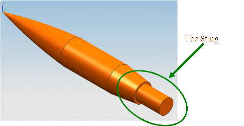
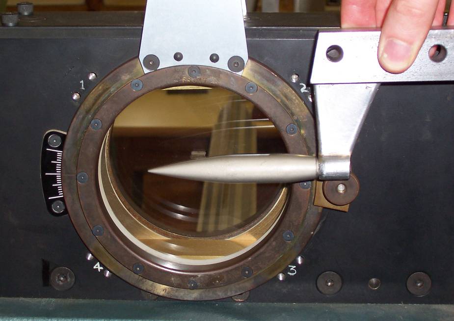
The initial requirement for using most RP machines is the input of a STL file. To generate a STL file, a high quality CAD model must be generated. Figure 1 shows a CAD model of the SOCBT (Secant-ogive-cylinder-boat-tail) projectile generated using NX5 parametric modelling software. The SOCBT projectile is selected because it has been used for a range of scientific study [28−32], consequently aerodynamic data and characteristics can be sought. The projectile consists of a three-calibre long secant ogive nose, a two-calibre long cylindrical mid section and a one-calibre long 7º conical boat tail. The geometry was modified to include a sting necessary to mount the model in the wind tunnel as illustrated in Figure 2.
The CAD model was converted into the STL file format. To examine and ensure high quality geometry definition the file was imported into STL file correction software (Materialise Magics) was applied. The aim of the correction software is to create one complete shell comprised of all the triangular facets which accurately approximate the original CAD geometry. One shell will fully define the part and is used by the SL machine to direct the laser and build the model. Within programs such as ‘Magics’ the user can choose the desired process and specific machine to be used for the build. One crucial step is choosing the layer thickness for the part. Thin layer thicknesses result in higher resolution, and often a better representation of the CAD model. However, with more layers the build time will increase. Once the layer thickness is specified, the STL file is sliced in the horizontal plane.
| RP Process | Strength | Temperature Resistance | Accuracy | Post-processing | Process available |
|---|---|---|---|---|---|
| SLA | 3 | 3 | 5 | 3 | yes |
| FDM | 3 | 2 | 3 | 4 | yes |
| SLS | 3 | 1 | 4 | 3 | yes |
| DMLS | 4 | 4 | unknown | 2 | no |
| SLM | 5 | 5 | unknown | 2 | no |
| EBM | 5 | 5 | unknown | 2 | no |
| LENS | 5 | 5 | unknown | 2 | no |
| Process | Company and Machine(s) | Materials available | Advantages | Disadvantages |
|---|---|---|---|---|
| Liquid Based Processes | ||||
| SL Stereo-lithography | 3D Systems: Viper Pro SLA 7000 SLA 5000 | 10 from 3D Systems, including Accura® Bluestone + 3rd Party Suppliers | Most mature technology with proven use in industry. Provides greatest accuracy, highest dimensional tolerances and best surface finish. Can produce particularly intricate and complex parts. SLA 7000 is a relatively quick RP process and can be significantly quicker than traditional techniques. This process has lower power consumption than powder-based processes. | Relatively expensive ~£600,000 for SLA 7000. Limited choice of materials for functional parts. Additional equipment is required including dehumidifiers, UV oven and UV shielding. High material & running costs. Physical properties degrade with time, parts experience hygroscopic degradation as they absorb moisture and UV degradation as they continue to cure. Resins are not environmentally friendly and future EU legislation may aim to limit their use. |
| Solid Based Processes | ||||
| FDM Fused Deposition Modelling | Stratasys: FDM Maxum FDM Titan FDM 3000 | ABS Polycarbonate Elastomer Polyphenysulfone | Much cheaper than most laser-based processes up to~£100,000. Proven use in a wide range of industry. Fewer health, safety and environmental considerations than other processes. Parts retain physical properties unlike SL & SLS | Resolution of small features and intricate shapes not as good as SL or SLS. Slow build. Expensive materials which may not suitable for supersonic wind tunnel testing. Poor definition. Parts can be porous, reducing the suitability for pressure tapings. |
| Powder Based Processes | ||||
| SLS Selective Laser Sintering | 3D Systems: Sinterstation Pro Sinterstation HiQ Vanguard | Duraform PA & GF LaserForm™ ST100 LaserForm™ ST 200 LaserForm™ A6 | A wide choice of materials is available many of which can be used for limited functional parts. Good accuracy and dimensional tolerances. Proven use in industry. The HiQ model can produce polymer, metal and ceramic parts. High throughput can be achieved with efficient use of the build chamber. No support structure required (for polymers), allowing full geometric freedom, intricate and complex parts. | Approximately £500,000 to purchase and high running costs. Slower part building than SL. Requires temperature and ventilation control and nitrogen generator. ‘Green’ metal parts only ~60% dense and require a furnace for post-process infiltration. Hygroscopic degradation occurs with some materials. |
| EOSint, DMLS, Direct Metal Laser Sintering | EOS GmbH: M 270 M 250X | Stainless steel, cobalt chrome and titanium based materials | Can produce dense metal parts with higher strength physical properties than SLS, fine part detail. No post-process infiltration required. | M270 ~£300,000. Density variation can occur with parts. Shot-peening and polishing is required to give smooth surface finish. Slower processing time than SLS or SL, although has potential to be quicker than traditional techniques, for complex parts. |
| Metal Powder Based Processes (intended for fully functional parts) | ||||
| SLM Selective Laser Melting | MCP-HEK: Realiser Concept Laser: M3 Linear | Stainless steel powder CL 50 WS - Steel based | Can create fully dense metal parts with excellent physical properties. Potential for high strength parts suitable for wind tunnel testing. ‘M3 linear’ produces the largest metal parts of any RP machine. | An expensive process. Relatively new technologies, not widely used in industry. Parts may require surface finishing. |
| EBM Electron Beam Melting | ARCAM | Titanium and Cobalt-Chrome based alloys | Can create fully dense metal parts with excellent physical properties. Potential for high strength parts suitable for wind tunnel testing. High scanning speed means this technology tends towards full scale Rapid Manufacture. | Approximately $470,000 to purchase. Relatively new technology, limited industrial use compared to SLA and SLS. Has been reported to sometimes produce a poor surface finish, therefore component quality needs to be verified. Running costs unknown. |
| LENS Laser Engineered Net Shaping | Optomec LENS 850R | Stainless Steels, Titanium, Nickel based alloys | Very promising technology. Creates metal parts with excellent physical properties. Potential to produce parts for wind tunnel testing. Can be used to add material to existing worn or damaged parts. | Expensive. Large machines not suited to office environment. Limited use in industry – 4 systems used by US Military, running costs unknown. |
Numerous two-dimensional slice files are produced and used by the RP machine to build the model layer by layer.
For safety, typical values of surface temperature distribution and aerodynamic loading for the wind tunnel model can be estimated from computational fluid dynamics (CFD) computations. Figure 3 provides an example of such numerical simulation for the SOBCT projectile placed in a section of a wind tunnel.
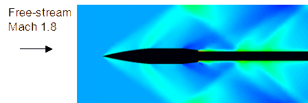
The CFD analysis has correctly identified the complex flow characteristics anticipated for the SOCBT projectile placed in the wind tunnel. The typical velocity of an artillery shell is Mach number 2.5 and consequently the maximum temperature that a wind tunnel model must withstand is about 290°C. The size of the model was dictated by the specification of the wind tunnel shown in Figure 2. The dimensions of the model were set to: length 105 mm, max diameter 15 mm, surface area 3,812 mm², and volume 11,677 mm³. The number of triangular facets in the STL file was 10,796.
Model manufacture
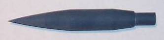
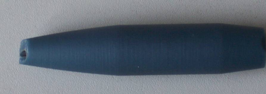
The STL file for the SCOBT model was manufactured on a 3D Systems SLA 7000 machine using Accura Bluestone courtesy of Renault F1 UK. Figure 4 shows one of the models.
The next requirement was to find out how many pressure tapings could be located in the model. Bluestone is a brittle material not ideally suited to machining, while attempting to locate three pressure tapings at specific positions, two models were damaged, Figure 5. Thus it is recommended that pressure tapings are incorporated into the CAD model, and therefore manufactured into the part using the RP process.
To improve the temperature resistance and lower the roughness of the surface the remaining models were sent to 3D definitive coatings to be nickel plated, Figure 6.
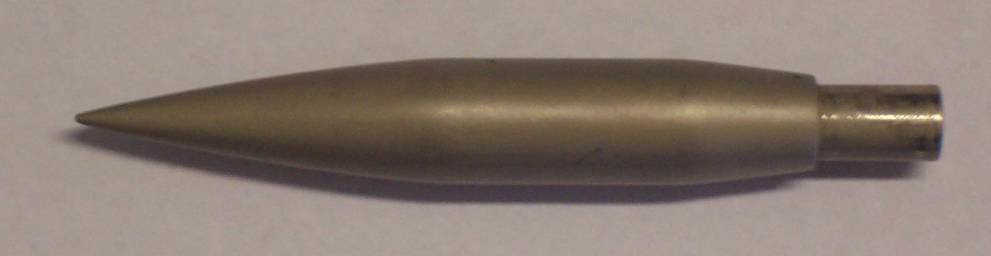
As highlighted in Figure 6, the nickel plating has rounded the tip of the nose. This will affect the flow over the projectile. Instead of an attached bow shock, it is anticipated that the model will produced a detached bow shock. The surface roughness of the model was measured using a diamond studded drag-probe. The roughness was Ra = 0.655 μm, this was judged suitable for supersonic wind tunnel testing.
For comparison models representative of a typical artillery shell (simple geometry) and a mortar bomb (complex geometry) models were manufactured using SL technique, see Figures 6A-7A. Figures 6B-7B show the corresponding CAD models. Note that the geometries have been simplified.
Figure 6A. SL artillery shell model.
Figure 6B. Artillery shell CAD model used for rapid prototyping.
| Model | Length | Largest Diameter | ||||
|---|---|---|---|---|---|---|
| Intended | Actual | % diff | Intended | Actual | % diff | |
| SOCBT | 105 | 104.95 | 0.05 | 15 | 14.98 | 0.13 |
| Bluestone | ||||||
| Nickel Plated SOCBT | 105.20** | 103.86 | 1.3 | 15.20** | 15.22 | 0.13 |
| Shell | 105 | 105.02 | 0.02 | 16.33 | 16.27 | 0.37 |
| Mortar | 90 | 90.06 | 0.07 | 15 | 14.97 | 0.2 |
Figure 7A. SL mortar bomb model.
Figure 7B. Mortar bomb CAD model used for rapid prototyping.
Table 3 shows the dimensional accuracy of the manufactured projectile models. The nickel-plated SOCBT model has the largest percentage difference.
The surface roughness of the SL parts is relatively poor. The SLA 7000 machine is capable of producing parts with smooth surfaces and fine detail. It can be surmised that these models may have been manufactured using the FAST build style which uses 0.127 mm layers as opposed to 0.025 mm layers used to produce better quality surfaces. Should these models be required for wind tunnel use, the surfaces could be smoothed with TPM solvent, albeit reducing the dimensional accuracy.
Conclusions
The project has concluded that a metal-powder based RP process is most appropriate for manufacturing prototypes and models for supersonic wind tunnels. This is due to the superior physical properties of such parts. Hence this methodology is recommended for an industrial application, where businesses will have freedom to choose the most appropriate process for their specific requirement. It should also be noted that the metal-based processes can satisfy a wide range of requirements, particularly for low volume manufacture of highly complex parts.
For the scope of the Study, SL was chosen because it can manufacture parts with sufficient accuracy and surface finish, this methodology is supported by the general consensus of literature reviewed. Combining SL with the Accura Bluestone material provides the best physical properties for supersonic wind tunnel testing of the all remaining RP options. Using Accura Bluestone is also recommended for subsonic model manufacture because it has been specifically designed for this purpose. Although, it should be noted that other SL materials have been used for subsonic wind tunnel models.
For supersonic testing, the potential danger of high temperatures and the proposed solution of nickel plating should be investigated further, as it does not appear to be the best option. After nickel plating the model geometry was altered. The most critical part of the geometry—the nose tip—was blunted. The geometry change means that this is not the best option in practice, unless the plating method can be improved or avoided. The change of geometry can be partially alleviated by appropriately reducing the size of the model prior to the coating. However, rounding of sharp edges is difficult to avoid.
The artillery shell models would be feasible for use in a subsonic wind tunnel, although the current roughness makes them unsuitable. This roughness is thought to be a limitation of the scanning strategy used, not a limitation of the SL process. With a more refined scanning strategy in the SL machine and hence thinner layers, minimal post-processing would be required to use the models in the subsonic wind tunnel, whilst maintaining dimensional accuracy.
Hence it can be concluded that for all RP process, projectile models should be manufactured at the highest available resolution, this will minimise post-processing requirements which can degrade the dimensional accuracy of parts.
Overall the presented methodology requires a better material, which can be provided by the more recent metal-based RP process. Off these technologies, DMLS using the EOS M270, or SLM using the MCP Realiser are thought to be the most promising alternatives.
It can also be concluded that when making wind tunnel models from SL materials. The pressure tapings should be incorporated into the build. Otherwise the parts can be damaged when drilling pressure tapings, due to the brittle nature of the materials.
Polymer-based models are useful for low-stress applications but may not be suitable for direct application in supersonic wind tunnel testing. However, metal-based technologies hold new promise.
Acknowledgements
Discussions and contributions from Martin Johnson and Graham Tromans are gratefully acknowledged. The authors are grateful to Renault F1 UK and 3D Definitive Coatings, without whom it would not be possible to manufacture models of the projectiles.
References
[1] T. Grimm, “User’s guide to rapid prototyping.” Dearborn, Michigan: Society of Manufacturing Engineers; 2004.
[2] R.N. Chuk and V.J. Thomson, “A comparison of rapid prototyping techniques used for wind tunnel fabrication”, Rapid Prototyping Journal, 1998, 4(4): 185−196.
[3] A. Springer, “Evaluating aerodynamic characteristics of wind tunnel models produced by rapid prototyping methods’” Journal of Space Craft and Rockets, 1998, 35: 755−759.
[4] C. Tyler and W. Braisted, “Evaluation of rapid prototyping technologies for use in wind tunnel model fabrication” AIAA Aerospace Sciences Meeting and Exhibit, Reno, Nevada; 2005.
[5] R. Aghanajafi, R. Adelnia, and S. Daneshmand, “Production of wind tunnel testing models with use of rapid prototyping methods” WSEAS Transactions On Circuits and Systems Issue 4, 5; 2006.
[6] A. Springer, K. Cooper, and F. Roberts, “Application of rapid prototyping models to transonic wind tunnel testing” AIAA Paper 97−0988, 1997.
[7] A. Springer and K. Cooper, “Comparing the aerodynamic characteristics of wind tunnel models produced by rapid prototyping and conventional methods” AIAA Paper 97−2222, 1997.
[8] Castle Island Co,URL: http://home.att.net/~castleisland/sl.htm [15/11/2007].
[9] A. Springer, F. Roberts, and K. Cooper, “Application of rapid prototyping methods in high speed wind tunnel testing”, Project 96−21, NASA Marshall Space Flight Centre, 1997.
[10] 3D Systems Inc, SLA 7000 System UK Data Sheet, available from: 3D Systems Inc, URL: http://www.3dsystems.com/ products/sla/sla7000/datasheet .asp [13/12/2007].
[11] C.K. Chua, K.F. Leong, and C.S. Lim, “Rapid prototyping principles and applications”, Singapore: World Scientific Publishing Co. Pte. Ltd; 2003.
[12] N. Hopkinson, R.J.M. Hague, P.M. Dickens, “Rapid Manufacturing: An industrial revolution for the digital age”, Chichester, West Sussex: Wiley & Sons Ltd; 2006.
[13] R. Aghanajafi, S. Daneshmand, R. Adelnia, “Comparison between FDM model and steel model as wind tunnel testing models” WSEAS Transactions On Circuits and Systems Issue 4, 5; 2006.
[14] 3T RPD Ltd, DMLS Brochure, Berkshire UK; 2008, available from: 3T RPD Ltd, URL: http://www.3trpd.co.uk/dmls/ index.htm [25/03/2008].
[15] E.C. Santos, M. Shiomi, K. Osakada, T. Laoui, “Rapid manufacturing of metal components by laser forming” International Journal of Machine Tools & Manufacture 46, 2006; 1459−1468.
[16] Y.V. Tolochko, S.E. Khlopkov, S.E. Mozzharov, M.B. Ignatiev, T. Laoui, and V.I. Titov, “Absorbance of powder materials suitable for laser sintering”, Rapid Prototyping Journal, 2000, 6 (3); 155−160.
[17] B. Lauwers, J.P. Kruth, L. Froyen, and T. Laoui, “Comparison between Nd:YAG and CO2 Laser for use with selective laser sintering of metal powders”, Proceedings of the PHOTOMEC’99−ETE’99, European workshop, Liege, Belgium, 1999; 165−173.
[18] K.G. Cooper, “Rapid prototyping technology selection and application”, New York: Marcel Dekker Inc; 2001.
[19] A. Kochan, “Rapid prototyping helps Renault F1 Team UK improve championship prospects” Assembly Automation, 2003, 23 (4); 336−339.
[20] A.L. Heyes and D.A.R. Smith, “Rapid technique for wind-tunnel model manufacture”, Journal of Aircraft, 41 (2), 2003; 413−415.
[21] K.A. Ghany and S.F. Moustafa, “Comparison between the products of four RPM systems for metals” Rapid Prototyping Journal, 2006, 12 (2); 86−94.
[22] M.L. Griffith, T. Ensz, J.D. Puskar, and C.V. Robnio, “Understanding the microstructure and properties of components fabricated by laser engineered net shaping (LENS®)”, Materials Research Society, Symposium Y Proceedings 625, 2000; 9−20.
[23] M. Hedges, “Laser based additive manufacturing using LENS™ and M3D™”, Proceedings of the Fourth Laser Assisted Net Shape Engineering, LANE, 2000, 1; 523−534.
[24] T. Sexton, S. Lavin, G. Byrne, and A. Kennedy, “Laser cladding of aerospace materials”, Journal of Materials Processing Technology 122, 2002; 63−68.
[25] X. Wu, R. Sharman, J. Mei, and W. Voice, “Direct laser fabrication and microstructure of a burn resistant Ti alloy” Materials and Design 23, 2002; 239−245.
[26] F. Liou, K. Slattery, M. Kinsella, J. Newkirk, H.S. Chou, and R. Landers, “Applications of a hybrid manufacturing process for fabrication of metallic structures” Rapid Prototyping Journal, 2007, 13 (4); 236−244.
[27] D.T. Pham, C. Ji, C.C. Dimov, “Layered manufacturing technologies”, Proceedings of the First International Conference on New Forming Technology, ICNFT, 2004; 317−324.
[28] R. Cayzac, E. Carette, M. Péchier, P. Guillen, and R. Thépot, “Navier-Stokes computations and validation of yawing and spinning projectiles” Proceedings of the 18th International Symposium on Ballistics, San Antonio, Texas, 1999, 1(1): 28−37.
[29] J. Sahu, “Computations of transonic flow over projectiles at angle of attack” Proceedings of The 11th International Symposium on Ballistics, Brussels, Belgium, 1989, 1: 761−770.
[30] J.K. Fu and S.M. Liang, “Drag reduction for turbulent flow over a projectile: Part 1” Journal of Space Craft and Rockets, 1994, 31(1): 85−92.
[31] S.M. Liang, J.K. Fu, “Drag reduction for turbulent flow over a projectile: Part 2” Journal of Space Craft and Rockets, 1994, 31(1): 93−98.
[32] C.J. Nietubicz and K.O. Opalka, “Supersonic wind tunnel measurements of static and Magnus aerodynamic coefficients for projectile shapes with tangent and secant ogive noses”. US Armament Research and Development Command, Ballistic Research Laboratory Report, Aberdeen Proving Ground, Maryland, 1980.
Dr Joanna Szmelter moved to Loughborough University from Cranfield University (Shrivenham Campus) in October 2006 where she was a senior lecturer in the Ballistics and CFD Group. Prior to that she was in charge of the Aerodynamic Technology Group at BAe Airbus Ltd and earlier she had held various research posts at Swansea University. E-mail:j.szmelter@lboro.ac.uk.
Mr Paul R Williams obtained an MEng degree at Loughborough University in July 2009. Prior to graduation he completed a placement year with BAE Systems—Land Systems, working in Manufacturing Engineering, Trials and Reliability Engineering and Urgent Operational Requirements.