
Volume 12, Number 2, July 2009
Portable Electro-Optic Device For Performing Serviceability Checks On Laser-Guided Munitions
- 1 Laser Science and Technology Center (LASTEC), Defence Research and Development Organization (DRDO), Metcalfe House, Delhi-54, India.
Abstract
Precision-guided munitions (PGM) including laser-guided bombs (LGB), projectiles and missiles and IR guided air-to-air (AAM) and surface-to-air missiles (SAM) are widely exploited weapons because of their precision strike capability. The efficacy of the mission involving delivery of laser-guided munitions largely depends upon the envelope of weapon release from the launch platform and the functionality status of the weapon at the time of release. Laser-guided munitions make use of laser radiation scattered by the target after it is illuminated by a laser target designator. The laser target designator and the laser seeker used in the guided weapon use the same PRF code in a given mission and the weapon homes on to the source of laser scatter once a PRF code is matched. PRF code compatibility between the designator and the laser seeker therefore is essential to the weapon’s functionality and mission success. Though periodic functionality or readiness checks on this class of guided weapons may involve checking field-of-view, linearity and sensitivity in addition to PRF code compatibility; it is the PRF code compatibility check that is considered as the litmus test for establishing the serviceability of the weapon. This paper presents the design and development of a portable electro-optic device that generates the signatures in terms of amplitude, wavelength, and PRF code of the laser radiation scattered from the target as seen by the laser seeker used in LGB delivery applications. The device was used to perform serviceability checks on laser seekers of foreign origin.
Introduction
Because of their precision-strike capability, laser-guided munitions, which mainly include air-to-surface laser-guided bombs and missiles and surface-to-surface laser-guided projectiles and missiles, are the most widely used precision-guided weapons in the contemporary battlefield. Their efficacy has been established beyond the slightest doubt in several major wars in the last couple of decades [1-2]. Laser-guided munitions home on to the target that is the source of scatter of laser radiation of a wavelength and PRF code known to the laser seeker used in the weapon once the intended target has been illuminated or designated by the laser target designator. The laser target designator and the guided weapon are either co-located on the launch platform or are separated [3]. A common laser-guided bomb delivery mode employs a land-based target designator and aerially delivered guided weapon (Figure 1).
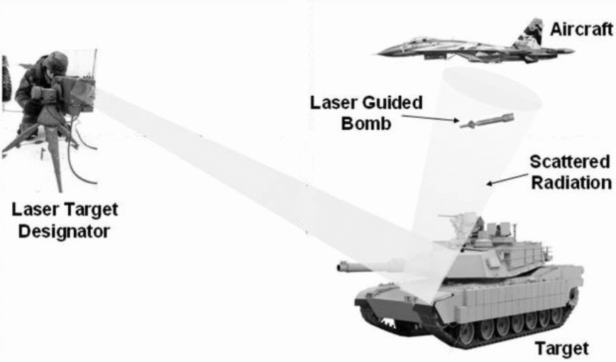
Laser target designator used in such applications is typically a high repetition rate (10−20 pulses per second), Q-switched Neodymium-YAG laser with pulse width in the range of 10−20 ns and pulse energy in the range of 50−120 mJ. These designators offer a set of discrete PRF codes specified in terms of time interval between two successive laser pulses. The PRF code is usually specified with an accuracy of ± 1 µs in time interval. If we can simulate the desired laser parameters in terms of wavelength, pulse width, power density and the PRF code as would be seen by the laser seeker cross-section due to scatter from the laser designator-illuminated target, the device could be usefully employed as a test device for performing serviceability checks.
The proposed electro-optic device uses an innovative design concept to simulate the laser target designator signatures in terms of amplitude, wavelength, and PRF code as seen by laser seeker cross-section. Major specifications of the device include output wavelength of 1064 ± 2 nm, selectable pulse width of 10 and 20 ns, selectable pulse repetition frequency (PRF) in the range of 5−50 Hz with a time interval resolution of ±1 µs and selectable power density levels of 10 µW/cm2
and 1mW/cm2. The device produces a near collimated beam of 75-mm diameter at the exit with a full angle divergence of about 40 µrad.
The power density available at the laser seeker cross-section at a given distance from the target due to a laser designator of known specifications for given values of distance between the designator and the designated target, target reflectivity and visibility conditions can be computed from various mathematical models available in the literature [4].
Though comprehensive test set-ups exist for characterization of laser seeker units [5-6] in terms their vital parameters, these cannot be used to perform a quick functionality check, more so when the weapon is mounted on to the launch platform. Therefore, there is always a requirement to develop portable electro-optic devices that can perform quick functionality checks on these weapons to ensure near 100% target hit probability. These devices can also be gainfully employed to generate vital data that is never available in the technical manuals of these weapons. The generated data in turn could be used for designing efficient countermeasure systems against similar weapons of an adversary.
Design approach
Taking advantage of the fact that the power density available at the laser seeker cross-section over minimum to maximum operational range typically varies from few tens of mW/cm2 to a few µW/cm2, the design of the proposed electro-optic device is configured around a high-bandwidth laser diode module operating at a nominal wavelength of 1064 nm and generating an output power of 50 mW. The laser diode is temperature stabilized with a thermoelectric cooler (TEC) and the associated control electronics to achieve the desired level of wavelength stability. The module has a bandwidth of 100 MHz which allows generation of laser pulses up to 10 ns pulse width. Though Q-switched Neodymium-YAG lasers producing few micro-joules of pulse energy are available and could be used to produce the desired power density levels with appropriate neutral density filters; these lasers along with the associated electronics tend to be much larger compared to diode lasers. Secondly, Neodymium lasers do not offer the flexibility of selectable pulse width. Thirdly, Neodymium laser of equivalent specifications would be far more expensive as compared to the diode laser.
The PRF code is generated by a microcontroller based embedded code generator subsystem which through its key pad interface can generate any pulse repetition frequency in the range of 5−50 Hz with time interval resolution of ±1 µs. The output of the embedded subsystem is fed to the driver electronics subsystem. The laser diode module is driven by the driver electronics subsystem that generates the necessary input waveform for the laser module with the required current levels. The output beam from the laser diode module is expanded by 25X beam expander. A neutral density filter is used to attenuate the laser power by a factor of 100 to get the second value of power density.
Design implementation
Figure-2 shows a block schematic of the device. The device is configured around the high-bandwidth laser diode module and the associated drive and control electronics. The pulsed waveform needed for triggering the laser diode module is generated in the embedded subsystem configured around microcontroller type 8051. The microcontroller is interfaced with 3×4 matrix key pad and 8×2 LCD display. The time period of the generated waveform is entered by the user from the key pad, which is subsequently displayed on the LCD display.
The output of the embedded code generator subsystem is fed to the driver subsystem. The driver subsystem comprises a buffer (type 74LS244), Monoshot (type 74ALS121) and another buffer (type 74LS244). The Monoshot controls the output pulse width of the drive waveform. The user can select a pulse width through a two-way switch. The selections available are 10 ns and 20 ns. The output of the Monoshot is fed to the buffer which in turn feeds the trigger input of the laser module.
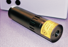
The laser diode module (make: Power Technology) chosen for the design has its output wavelength centered on 1064nm. It has a modulation bandwidth of 100 MHz, output power of 50 mW and FWHM of 0.5 nm. The module also has an in-built TEC and the associated control circuit to stabilize the diode temperature and hence the wavelength. Figure 3 shows the photograph of the module.
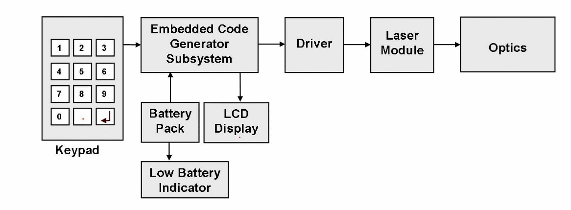
The device is battery operated and employs a 7.2-V / 3.5-AH rechargeable Li-Ion battery having built in protection against deep discharge. The device has an additional feature of low battery indicator. The low-battery indicator circuit provides LED indication when the battery voltage goes below a preset threshold.
The laser beam at the exit of the laser module has a diameter of 3.0 mm and a full angle divergence of 1.0 mrad. The laser beam is expanded by a 25X beam expander to get an output beam diameter of 75 mm. Consequently, the beam divergence reduces to 40 µrad. Laser seekers used in laser guided munitions typically have input apertures of 25−50 mm diameter. In a real deployment scenario, the seeker unit is always filled by laser radiation. Beam diameter expansion to 75 mm is to ensure that this condition is met.
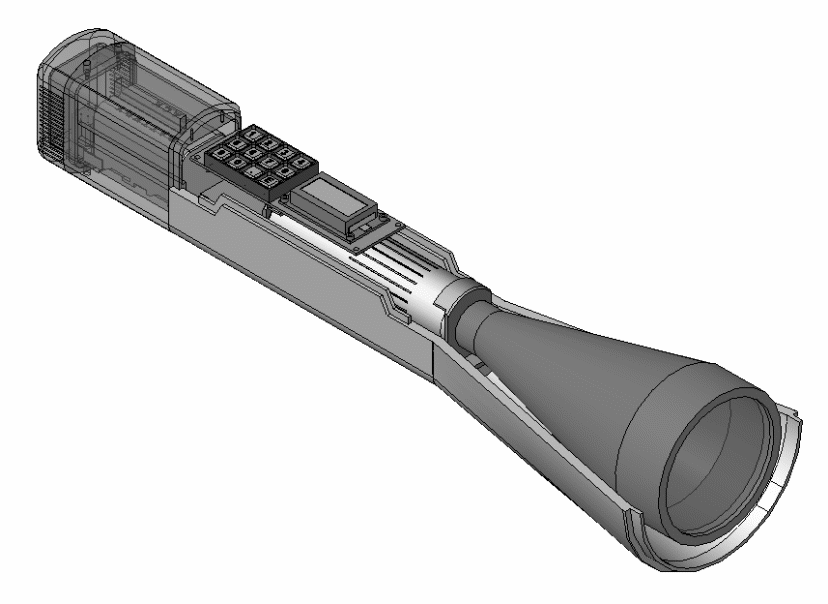
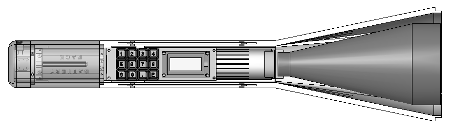
A borosilicate optical window is used at the output to protect the laser module. The power setting of 10 µW/cm2 can be generated by using an external neutral density filter assembly having an optical density of 2.0 at 1064 nm. A modular, portable, lightweight and easy-to-use mechanical package was designed for the device. Figure 4 shows two different CAD views of the mechanical package showing location of different subsystems and highlighting the modular construction.
Performance evaluation of the electro-optic device
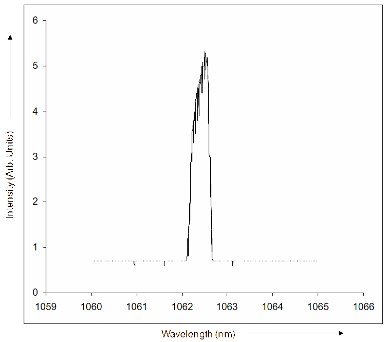
The prototype of the electro-optic device was comprehensively evaluated for its output wavelength spectrum, spot size and power density. The wavelength spectrum was plotted using UV-Vis-NIR spectrophotometer (make: VARIAN).
| PRF Code Selected (ms) | Measured Value (ms) | ΔT (µs) |
|---|---|---|
| 100.000 | 100.00027 | 0.27 |
| 50.000 | 50.00014 | 0.14 |
| 105.984 | 105.98433 | 0.33 |
| 106.188 | 106.18835 | 0.35 |
| 106.398 | 106.39837 | 0.37 |
| 106.598 | 106.59839 | 0.39 |
| 106.803 | 106.80339 | 0.39 |
| 107.008 | 107.00832 | 0.32 |
| 106.044 | 106.04431 | 0.31 |
| 105.042 | 105.04231 | 0.31 |
| 80.000 | 80.00022 | 0.22 |
| 106.610 | 106.61037 | 0.37 |
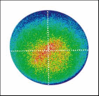
The measured spectrum is shown in Figure 5. The spot size was measured using a Laser Beam Profiler (Make: Newport). Figure 6 shows the relevant plot. The power density as measured at the centre of the spot was 1.05 mW/cm2. The prototype was also comprehensively tested for accuracy of PRF code generation using a frequency counter and a suitable sensor. Different PRF codes were selected one at a time. The output beam of the device was made to fall on an optoelectronic sensor which generated electrical pulses corresponding to the optical output of the device. The output of the optoelectronic sensor was fed to a high resolution counter (make: Fluke). Table 1 lists the selected PRF codes and the corresponding measured values. The PRF code accuracy was observed to be within ± 0.4 µs, which is much better than the required value of ± 1.0 µs.
Testing of seekers using the electro-optic device
The prototype of the electro-optic device was used to test the Lizard seeker unit (Make: Elbit Systems, Israel). Figure-7 shows the test set-up. The electro-optic device is kept at a distance of 2 m from the laser seeker. The output of the seeker is connected to a PC. When the seeker is powered on, it is in acquisition mode. The following tests were performed on the seeker unit.
- PRF code compatibility test
- False code rejection test
- Field-of-view test
- Sensitivity test
The test results are summarized as follows.
1. PRF code compatibility test: The same code was programmed into the laser seeker and the electro-optic device. The seeker responded to the coded radiation and went into the tracking mode from the acquisition mode. The performance of the seeker was checked for all its 14 codes and it responded to all the codes correctly (result = PASS).
2. False code rejection test: Different codes were programmed in the laser seeker and the electro-optic device. The seeker remained in the acquisition mode (result = PASS).
3. Field-of-view test: The electro-optic device was used to check the coarse field-of-view of the seeker. The device was mounted on a goniometer and was aligned with the seeker. The same code was programmed into the laser seeker and the electro-optic device and the seeker was observed to go from acquisition mode to tracking mode. The device was given rotation in one direction and the response observed. The seeker was observed to track the movement of the device and the angle at which it stopped responding gave the coarse field-of-view in one direction. A similar test was performed in the other direction. The coarse field-of-view was established to be ±15° (result = PASS).
4. Sensitivity test: The same code was programmed into the laser seeker and the electro-optic device and the seeker went from the acquisition mode into the tracking mode. The filter assembly having optical density of 2 was fitted in front of the device. The seeker still remained in the tracking mode. The seeker sensitivity was found to be better than 10 µW/cm2 (result = PASS).
Conclusion
The portable electro-optic device is primarily designed for carrying out a quick check on the vital operational parameters such as PRF code compatibility, immunity to false PRF codes, coarse estimate of field-of-view, and sensitivity of laser-seeker units. The device allows serviceability check of laser-guided munitions where the weapon is mounted onto a launch platform. In that case, the response of seeker unit is seen on the head-up display. The device generates two different power density levels to simulate two different ranges that allow the weapon to be checked at two ranges, one near the start of terminal guidance and the other close to the target. The proposed concept uses a high-bandwidth, temperature-stabilized laser diode module to generate the amplitude, wavelength, pulse width, and PRF code signatures of the laser radiation scattered from a target. A suitable beam expander achieves desired collimation and spot size and a neutral density filter gives two different power density settings. Two such devices when used in tandem could also be used to study the response of laser-seeker units to mixed PRF codes.
References
[1] B.D. Watts, “Doctrine, Technology, and War”, Air & Space Doctrinal Symposium, Maxwell AFB, Alabama, 30 April−1 May 1996.
[2] M.G. Vickers and R.C. Martinage, The Revolution in War, Center for Strategic and Budgetary Assessments, December 2004.
[3] D. Neuenswander, “Joint Laser Interoperability, Tomorrow's Answer to Precision Engagement”, Air & Space Power Journal, June 2001.
[4] R. Sabatini, “Tactical Laser Systems Performance Analysis in Various Weather Conditions”, Symposium on “E-O Propagation, Signature and System Performance Under Adverse Meteorological Conditions Considering Out-of-Area Operations, Italian Air Force Research and Flight Test Division (DASRS), Avionics and Armament Evaluation Service (SSAA), Italian Air Force Academy, Naples, Italy, 16-19 March 1998.
[5] R.G. Martin and E.L. Robinson, “Automated Laser Seeker Performance Evaluation System (ALSPES)”, Automated Testing of Electro-optical Systems, Society of Photo-Optical Instrumentation Engineers, 1988, pp. 73−77.
[6] D. Roberts and R. Capezznto, “AGM-114 Hellfire Missile System and FLIR/LASER Test and Integration on the H-60 Aircraft”, Proceedings IEEE Aerospace Conference, Vol. 3, 1999, pp. 63−72.