
Volume 12, Number 2, July 2009
Battle Field Damage Repair Of A Helicopter Composite Frame-To-Skin Junction
- 1 Both authors from: Eurocopter, Aéroport Marseille-Provence, 13725 Marignane Cedex, France.
Abstract
The paper focuses on the design and testing of a frame-skin-junction (FSJ) battle-damage repair (BDR) for use on a helicopter fuselage. Two instances of the FSJ were examined: i) FSJ located at a region where the fuselage skin terminates, with compressive frame buckling being the critical failure mode, and ii) FSJ located at a continuous skin region of the fuselage, where load transfer is mainly through the fuselage skin. Test specimens representative of the two repair instances were manufactured, and ballistic firing used to incur critical damage to each. Bonded/riveted patches and riveted aluminium angles for skin and frame BDRs respectively were then applied, and structural testing used to verify the performance of the repairs in-situ. The results of the structural testing indicated that the BDR procedure could recover the strength of each specimen, whilst adhering to the BDR operational criteria of limited application time and application simplicity.
Introduction
During combat missions, helicopter platforms may be damaged by projectiles whilst either in flight or on the ground. These projectiles cause damage to the aircraft structure, and, although in many cases not catastrophic in nature, can limit the operational capabilities of the platform through reductions in localised structural strength and rigidity. The high tempo of combat missions, and potential for spare-part shortages necessitate the need for rapid, simple and effective battle-damage repair (BDR) approaches that maintain the platform at a useful level of mission capability or, at the minimum, allow the platform to return to depot for servicing.
Délégation Générale Pour L’Armement (DGA)/Eurocopter in France and the Defence Science and Technology Organisation (DSTO) in Australia are jointly involved in the development of BDR techniques for use on helicopter platforms [1]. The French involvement has mainly focused upon the development of field BDR techniques, whilst DSTO have aimed toward the development of depot BDR techniques.
A survey to review the state of the art of the battle damage repair was conducted in this study. A sequent analysis conducted by the Structure Design department at Eurocopter led to the definition of flight-clearance criteria for a Military Rotorcraft (MR) with combat damage, on the basis of the regulations and helicopter substantiation documents [2]. Based on these flight-clearance criteria, the repair of such a helicopter structure can be grouped into two categories:
- Repair to allow continuation of flight without restriction.
- Repair to allow a return-to-base flight with an imposed flight envelope restriction.
In this study, focus was cast toward the damage and repair of a composite frame-to-skin junction (FSJ) to meet the case of continuation of flight without restriction.
The requirement for this repair was to re-establish the helicopters operational capability through restoration of its structural strength and rigidity to withstand the stress of the platforms flight envelope of the following mission. Consideration toward restoration of fatigue and corrosion resistance, which is generally not considered in BDR applications, was not considered in this study.
In this study, the BDR is considered to adhere to the following requirements:
- The BDR should be the best repair that can be applied under the prevailing conditions, with the available resources within a limited period of time to meet an operational need.
- The BDR procedure must use simple processes and tools, be simple in application and thus require a minimal amount of time to apply.
- The BDR should have a low sensitivity to the prevailing environmental conditions such as humidity, moisture, dust and changes in temperature.
The initial steps of this study was selecting typical FSJ areas for investigation, determining critical damage sizes in these areas, and defining suitable BDR methods. Based on a survey of the repair methods available, riveted or riveted/bonded repairs were identified as the best candidates as they meet the specified BDR requirements. The adhesive and rivet types appropriate to these types of repair were further selected and verified through coupon tests. Repair principles were then developed and detailed repair methods and procedures specified.
The FSJ BDR was then performed under conditions close to what would be expected in an operational environment. Eurocopter designed and manufactured test specimens that were representative of the identified critical areas. Based on knowledge acquired within the program, damage from the threat associated with each of these critical areas was identified, and ballistic firing was performed to generate such. This ballistic firing was performed at the Etablissement Technique de Bourges (ETBS) firing facility [3].
Following damage to the specimens, BDRs were applied in accordance with the developed procedures and techniques under simulated operational conditions at the Centre d’Essais Aéronautique de Toulouse (CEAT). Inspection of the resulting repair was then performed using IR thermography, and structural testing was conducted to characterise the performance of the BDR.
Identification of critical areas
As outlined, the study is focused toward the repair of a FSJ. Two specific instances of the FSJ were considered in this study as shown in Figure 1.
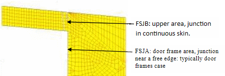
Associated critical failure modes and loads are different in these areas. Consequently, repairs procedures would also be different.
In the upper area (FSJB of Figure 1), an analysis of the aircraft FEM model indicated that, for critical load cases, the load transfer is predominantly though the platform skin (the critical load case occurs when the skin is in compression). In this area, the role of the supporting frame is to ensure general stability for the overall structure. According to criteria defined in this study, repair of the skin would be sufficient in battlefield conditions. The most suitable repair in this case would be to repair the hole resulting from ballistic impact by using a pre-cured composite patch system, which would assist in preventing crack propagation, and remove any stress concentrations arising from the hole in the skin caused by battle damage.
In the door fame area (FSJA), the critical failure mode is buckling in compression. An analysis of the general aircraft FEM model showed that the magnitude of load sustained by the skin is much lower than those sustained by the frame. However, if the frame fails, the adjacent skin will be subjected to over loading which could lead to skin failure. To prevent the buckling failure, any BDR applied must recover the frame’s bending rigidity.
Using these critical areas of investigation, Eurocopter’s stress department performed calculations to determine the required technical characteristics of the repair (such as patch dimensions, bonding strengths and rivet shear loadings) to meet the required structural safety margins in accordance with the BDR specifications. Through this study, specimen geometry and loading were also tailored for an ‘in-situ’ repair and structural testing at CEAT (details are given in Sections 5 and 6).
Selection of associated materials
In accordance with the BDR requirements, choice of materials for a repair must exhibit a low sensitivity to the environment during application, however still be easily applied with the limited resources available. The objective in this part of the study was to identify appropriate adhesive and rivets which best suit these BDR requirements.
Adhesive
The major requirement to be met for the selection of an appropriate adhesive is the application of such in hot and cold environments, as well as application on vertical surfaces.
Through a literature survey, four candidates were pre-selected in terms of the curing time and viscosity. In this phase of the survey, some other adhesives were not selected because they hardened too quickly at ambient temperature, and thus not suited for use in the BDR.
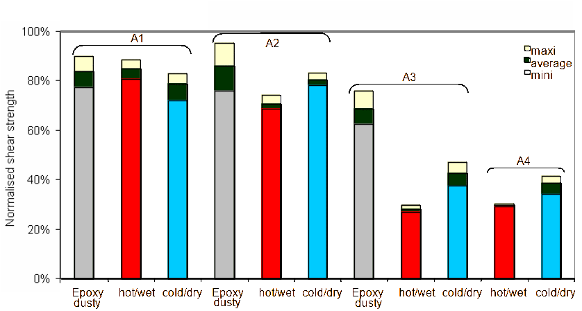
A manufacture trial of composite/metal and composite/composite bonded joints was conducted for each selected adhesive under a range of environmental conditions (dust, dry cold, and wet hot). Their respective performance when applied to a vertical surface is outlined in Table 1.
In addition to this, composite/composite single lap shear test specimens were bonded using the four adhesives outlined in Table 1 and tested under three different environmental conditions:
- Hot and wet (35°C, 85% RH).
- Dusty (ambient temperature and moisture, sanding without degreasing).
- Cold and dry (−10°C, 5% RH approx).
The results of the lap shear tests are presented in Figure 2. Based on these results, A2 was selected as the most appropriate adhesive for use in the BDR, which is a bi-component epoxy system.
Rivets
A commonly used rivet for composite structures was used as the reference. Six types of rivets potentially usable under BDR conditions were pre-selected based on the criteria of easy setting and broad thickness grip range.
Consequently, surveys were performed at the CEAT facility to determine the effect of different rivet setting on any damage incurred to the composite panel for the six rivets chosen. The survey involved installation of each rivet on a composite panel, followed with a micrographic analysis of the panel’s cross-section at the site of rivet installation. Two examples of the results from this analysis are shown in Figure 3 for rivets 2 and 3 (designated R2 and R3 respectively).
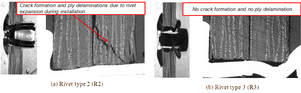
This investigation indicated that rivets 1 and 3 (designated R1 and R3) incurred no damage to the composite panel when installed, and thus were suitable for use.
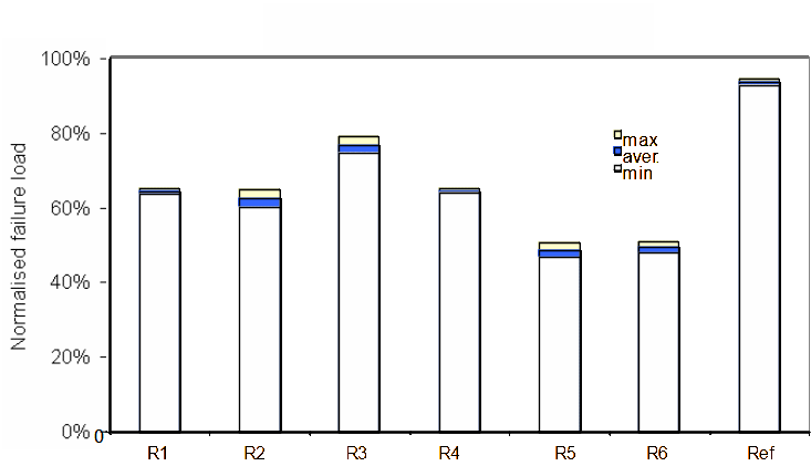
In addition to the micrographic analysis, shear tests for each of the six rivets were performed and compared to the reference rivet, with the results of this shown in Figure 4. In this test, R2 and R3 provided acceptable shear strengths compared to the reference rivet, making R3 the final rivet choice due to the failure of R2 in the outlined rivet installation test and micrographic analysis.
An additional test conducted by Eurocopter also indicated R2 to provide un-acceptably low tear off strengths, reinforcing R3 as the primary rivet candidate for use in the BDR.
Repair principles
1 FSJA repair region
In the FSJA area, as discussed in Section 2, it is necessary to recover the stiffness characteristics of the damaged frame, as the critical failure mode is buckling in compression of the frame. An efficient and quick method of doing this is to remove local rivets and to add a new riveted aluminium angle. In doing this, the repair performance is not influenced by environmental conditions as no adhesives are used, and the repair requires a limited number of tools, namely a hand drill and manual rivet gun.
It is important to use a rivet with a wide grip length range, which allows for a wide variety of assembly thicknesses, and thus may limit the rivet selection time. (The required rivet length grip is determined based upon precise measurement of the assembly thickness.)In addition, the use of the aluminium angle is in-line with BDR principles, being widely available, easy to procure and easy to machine.
2 FSJB repair region
The aim of a BDR in the FSJB area, as discussed in Section 2, is to recover the strength of the damaged skin, as the skin forms the main load path in this instance. For a skin repair of this type, the use of a riveted and bonded patch to repair the damaged area of the skin is effective. This repair is similar to the repair for general skin sandwich areas (without frame).
The repair may consist of one or more patches which are bonded and riveted to the parent structure. To speed the curing process, a heating unit and heat controller needs to be used.
Damage creation and repair
1 FSJA specimen
Damage creation
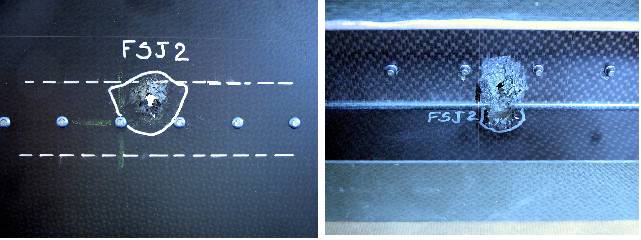
Figure 5 shows the FSJA specimen designed and manufactured by Eurocopter. Ballistic firing of the specimen was subsequently performed at the ETBS firing facility, with the results of this shown in Figure 6 and Figure 7, on two different FSJA specimens (FSJ1 and FSJ2).
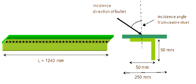
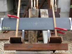
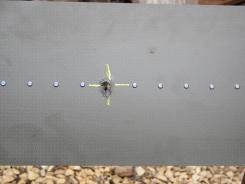
The ballistic firing was performed with a range of different bullet incident angles from 45° to 60° with respect to the rivet centre line as outlined in Figure 6. The large shot angles were used to create worse-case scenario damage to the frame.
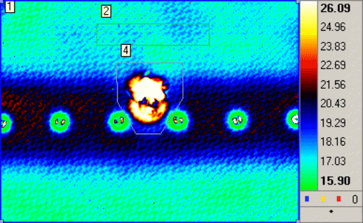
As can be seen from the ballistic impact results, damage to the FSJA was localised around the impact area, which is a classical behaviour of composites materials. Infrared thermography was used to inspect the damage from the specimen flat side. The results, as shown in Figure 8, confirmed the total damage area extended slightly from the external visible damage area.
Battle damage repair
The basic procedure used to apply the BDR to the FSJA specimen is as follows:
- Remove existing rivets to make way for the aluminium angle section.
- Position the aluminium angle repair part on the aircraft skin, keep it in place with hand and drill the airframe on one of the end rivets.
- Position the first rivet without closing it to allow for alignment of the aluminium angle.
- Install and close all rivets.
As can be seen, this procedure is simple, and requires a minimal number of tools to complete. Furthermore, as no adhesives are used in the repair, the repair performance is not affected by moisture, temperature or humidity at the time of application.
The most difficult task associated with the BDR installation was the removal of the existing rivets from the aircraft’s skin, some of which may be titanium depending upon the region and type of aircraft. It was found that team workers performing the repair should be appropriately trained to limit application time, with an untrained team found to perform the repair in around twice the time of a trained repair team.
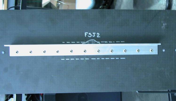
In order for the repair to prove effective in application, a stress analysis found that five rivets were required on either side of the damaged region as seen in Figure 9, with the rivets closest to the damage considered irreparable. All rivets to be used must also use the pre-existing rivet holes.
An image of the final repair as applied to the FSJA specimen can be seen in Figure 10.

2 FSJB specimen
Damage creation
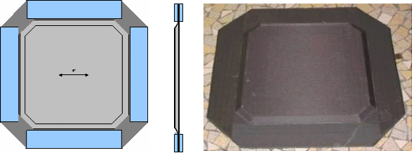
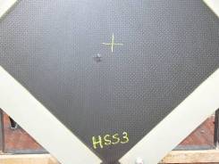
Figure 11 shows the FSJB specimen designed and manufactured by Eurocopter. Ballistic firing of the specimen was subsequently performed at the ETBS firing facility, with the results of these tests shown in Figure 11. Three FSJB specimens were manufactured and tested (HSS1, HSS2 and HSS3).
In this instance, the damage to the FSJB specimen was achieved using an incident firing angle of 60° from the surface tangent. This angle was chosen to maximise damage incurred to the specimen. An image of the impact damage can be seen in Figure 12.
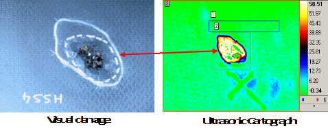
As with the results of the FSJB ballistic impact, the damage incurred to the FSJB specimen appeared to be localised around the impact point. Ultrasonic testing of the panel was performed, with the correlation between visual and ultrasonic results shown in Figure 13. In a separate study (not reported in this paper), the relationship between visual and effective damage sizes was established.
Battle damage repair
For the FSJB repair in this instance, three pre-cured composite laminates were used to repair the damaged skin. These patches were bonded on top of each other and onto the damaged skin as seen in Figure 14.
The procedure for repair of the FSJB specimen is as follows:
- Measure the maximum dimensions of the defect. The repair dimensions must provide a set overlap distance of the undamaged region of the skin. In curved areas, assembly of several matched and pre-cured flexible patches allows the repair to conform to the curve.
- Pre-position the patches over the damaged area, ensuring a defined offset of the patch area over the undamaged region of the skin, and pre-drill the rivet holes.
- Prepare the adhesive.
- Assemble and bond [4] the three patches.
- Position the three bonded patches onto the aircraft skin applied with adhesive, and rivet repair to the aircraft skin.
- Cure the bond using a heater controller.
This repair procedure typically takes two hours for a trained repair team to perform, including the bonding of the repair.
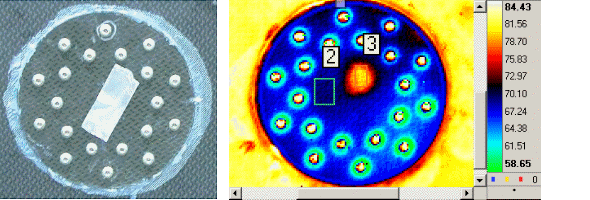
Using this repair procedure, a repair was performed on the FSJB specimen following ballistic impact damage, and IR thermography was used to inspect the quality of the repair. The results of this can be seen in Figure 15.
As can be seen by the uniformity of the thermography results, the resulting repair exhibited very good bond quality, and this was reflected in each of the three specimens examined. This bond quality was aided through the use of an interposition fabric to provide control over the bond line thickness across the bond area.
Structural testing
In order to verify the performance of the BDR process, structural testing of the resultant repairs for the FSJA and FSJB specimens was performed. Three specimens for each case were manufactured, damaged and repaired, and then structural testing for each of these three specimens for each design case was performed.
In order to simulate battlefield conditions, the repair for each specimen was performed within a two hour time constraint, and structural testing for the bonded repair was performed immediately after curing was completed in order to simulate flight loading following repair. In order for this to be achieved, the specimens were installed in the test machine, and the repair was performed in-situ, allowing loading following the two hour BDR application time.
1 FSJA battle damage repair
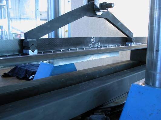
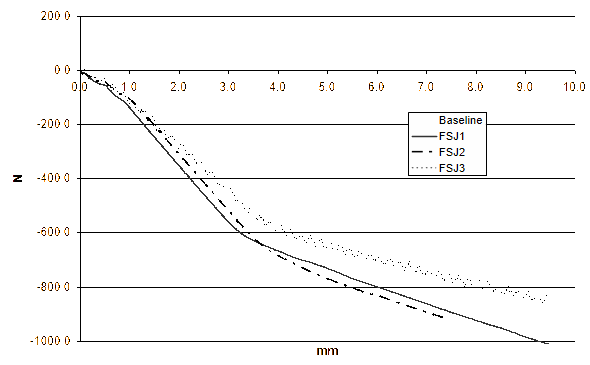
Structural testing of the FSJA specimen was performed using a three-point test rig as seen in Figure 16. Success of the repair is graded based on comparison of the load/displacement evolution with that of an undamaged specimen of the same geometry.

The load/displacement results for the three damaged and repair FSJA specimens as compared to an undamaged specimen can be seen in Figure 17.
As can be seen from the results, the load/displacement performance of the repaired specimens is closely comparable to that of the baseline (undamaged) specimen, particularly in the post-buckling region of the load displacement curve. Furthermore, the buckling (knee) point for each of the repaired specimens is in close agreement with what was theoretically calculated.
In the post-buckling region, the rigidity of each of the repaired specimens was observed to be slightly higher than that of the baseline, seen through the gradient of the force/displacement curves in the post-buckling region. This was thought to be a result of a slight specimen size difference between the baseline and repaired specimens.
These results suggested that the proposed BDR almost fully restored the structural behaviour of the frame in buckling due to compression, confirming the validity of the BDR approach in this instance.
2 FSJB battle damage repairfigure 19.fsjb load versus displacement curves for the baseline (undamaged) specimen and the three damaged and repaired specimens in picture frame tests.figure 19.fsjb load versus displacement curves for the baseline (undamaged) specimen and the three damaged and repaired specimens in picture frame tests.
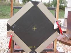
For the FSJB specimen, a picture frame shear test was used to load the specimen. The measured strengths were then compared with that of the baseline (undamaged) specimen to gauge the performance of the repair. The picture frame test set-up with the baseline specimen can be seen in Figure 18. The results of the testing can be seen in Figure 19.
As can be seen from the results, the repair nearly fully restored the shear strength of the structure. As a result of this performance, the BDR is deemed to be successful.
Similar to the case FSJA the measurement results were in close agreement with what was theoretically calculated.
Summary
The study focused on two specific occurrences of the FSJ, and the design of BDRs for each of these occurrences. Through FEM modelling, critical failure modes for the two cases were identified, and appropriate repair schemes were developed. Use of a composite patch bonded and riveted to the skin section and use of a riveted aluminium angle were identified appropriate to restore structural integrity for these two FSJ regions.
Coupon testing was performed to identify an appropriate adhesive system with minimal sensitivity to changing environmental conditions and appropriate workability for use in the BDR. In addition, an appropriate rivet type was sourced, based upon shear strength in application, and avoidance of any damage to the composite into which such was installed.
The performance of the BDR test specimens demonstrated that it is possible to install a FSJ BDR and restore structural integrity to the damaged area of a helicopter platform. Furthermore, this procedure can be performed in a field condition, under a time constraint with the performance of the repair exhibiting low sensitivity to the environmental conditions in which it was installed.
This paper reports Eurocopter’s contribution in the research collaboration between DGA/Eurocopter and DSTO. The work conducted by DSTO and their subsequent work are reported in separate publications [6]. The research conducted and outcome achieved by Eurocopter and DSTO are consistent with and in support of each other.
References
[1] Technical Arrangement between Minister for Defence of Australia and Minister for Defence of French Republic Concerning Battle Damage Repair of Helicopter Structures, TA 07/01, 2001.
[2] Eurocopter, Substantiation Document, Eurocopter, France.
[3] French Army, Battle Damage Specifications, France.
[4] Eurocopter, Aircraft Bill of Materials, Eurocopter, France.
[5] Eurocopter, Out of Autoclave Hot Bonding, Eurocopter Specification, Eurocopter, France.
[6] J. Wang, A. Gunnion, and A. Baker, “Battle Damage Repair of a Helicopter Composite Frame-Skin Junction: (1) Depot Repair”, accepted for publication in Journal of Composites: Part A; and (2) “A Reverse Engineering Approach for Rapid Repair Applications”, to be submitted to Journal of Composites: Part A.
Dr Jean-Evrard Brunel is from the EC Material & Process Laboratory, where he is in charge of Composite Mechanical Characterization and Composite Part Repairs and responsible for the ECG Material Data Base. He is an EADS Expert in Composite Material, Basic Processes and Calculation. Another part of his activities is the definition of composite structures repairs processes.
Mr Benoît Gresle is the Eurocopter Materials and Processes Research Programs Manager, where he is responsible for the development of advanced composite technologies. Another part of his activities is to coordinate Eurocopter R&T inside EADS.