
Volume 12, Number 2, July 2009
Anti-Tank Mine Blast Effects
- 1 MBDA—TDW Schrobenhausen, Hagenauer Forst 27, 86529, Schrobenhausen, Germany.
Abstract
Damage of vehicles caused by anti-tank mines is mostly credited to the transferred shock waves. The author subdivides the blast load into a close-field effect with the bulge in the belly plate and the global effect which accelerates the total vehicle with enormous force (magnitudes) and leads to damage on separated masses. These results are based on the described tests concerning the bulging acceleration in small scaled distances and the measured global impulses of mines lying on the ground, level to the ground, and buried 100 mm deep. The magnitudes of loads exerted by the shock waves and by the acceleration are discussed in detail.
Introduction
Anti-tank (AT) mines are a serious threat against all vehicles including trucks, armoured personnel carriers (APCs), and main battle tanks (MBTs). Ogorkiewicz [1] has listed the following consequences of AT-mine explosions:
- Impact of shock wave on a vehicle sets off stress waves in its hull with their peak in floor plate as high as 240,000 g.
- Blast wave can cause considerable dynamic deformation of hull floor plates, which can bow inwards as much as 150 mm and then spring back.
- Blast wind creates a drag force on vehicle tending to lift and overturn it.
- Soil ejecta augment blast wave and blast wind loading but their effect is more directional because the explosion is confined by the soil and varies with density and moisture content of soil as well as the degree of confinement.
Ogorkiewicz added to this verbal description a picture (Figure 1) which illustrates the above points. While the above points are not directly incorrect, they do deviate partially from physical aspects. He then followed with a presentation of a number of excellent examples for the reduction of damage from AT mine blast.
![Description of AT-mine blast effects (after Ogorkiewicz [1]).](/journals/journal-of-battlefield-technology/volume-12/issue-02/assets/12-2-1-held/figures/figure01.jpg)
The products of explosives expand extremely rapidly in the close field of a detonating conventional high-explosive charge, compressing and pushing the surrounding air like a piston. The molecules are moving with high velocities and create side-on and strong reflected stagnation pressures on target plates or structures. Describing this process as a wind is a little misleading, because this is a singular event of a few milliseconds duration.
Dosquet [2] presented an excellent description of the total loading transfer mechanisms of an AT mine strike (Figure 2), although the term ‘elastic deformation’ could be modified to be ‘elastic/plastic deformation’ and the expression ‘shock transfer’ could be better expressed as ‘load transfer’ in the figure. Load transfer refers to the extremely high accelerations and the damage caused by inertial forces on masses that are not integrated. Dosquet also goes deeper into the later phases of the attack, up to the crew vulnerabilities ([3,4]).
![General loading transfer mechanisms with detailed differentiation of the load transfer from the vehicle structure to the crew in AT-mine strikes (after Dosquet [2]).](/journals/journal-of-battlefield-technology/volume-12/issue-02/assets/12-2-1-held/figures/figure02.jpg)
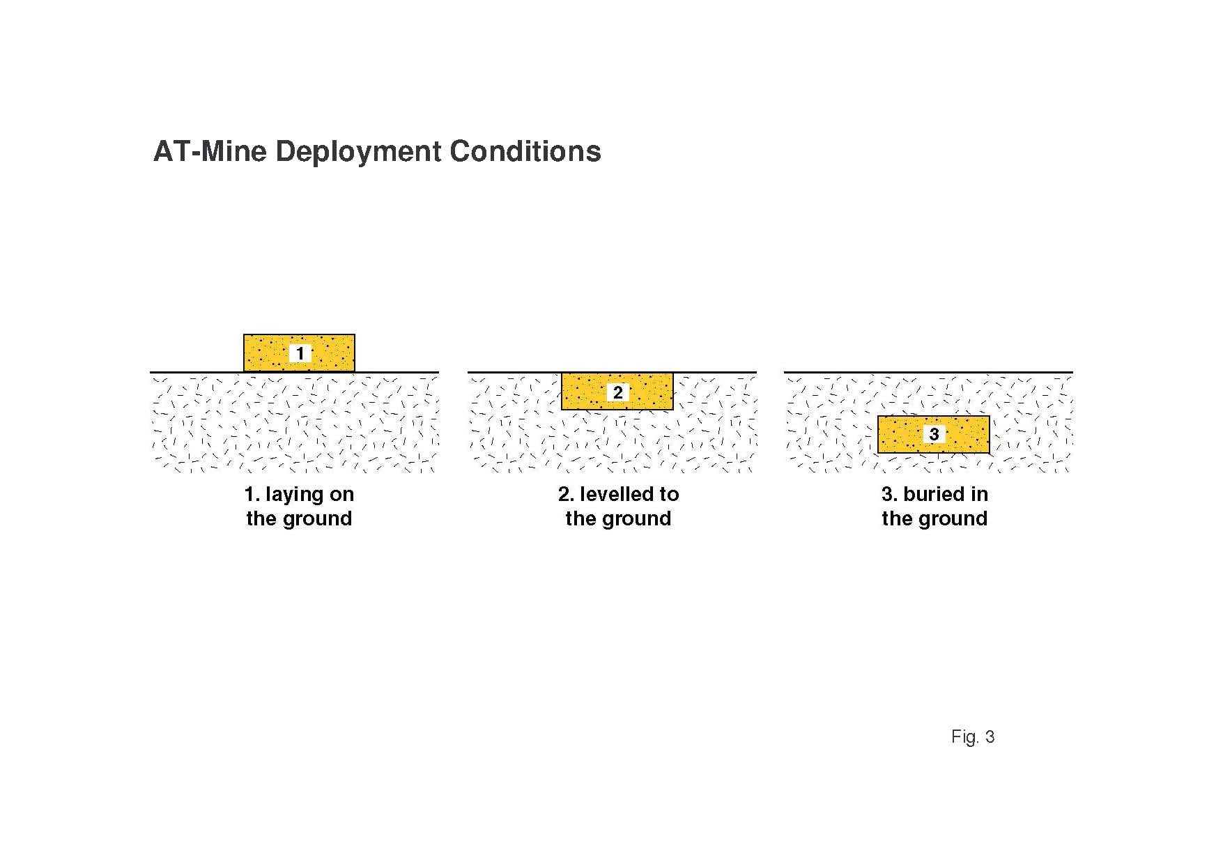
This paper presents a physically correct and precise description of the loads by AT mines on vehicles in the primary phase, using experimentally achieved test results ([5,6]) by firing high explosive discs in typical mine geometries under different deployment conditions against momentum blocks. The AT-mines can be deployed in three
typically different positions: lying on the ground, level with the ground, and buried in the ground (Figure 3). The results of such firings give interesting different typical impulse density contours.
Global impulsive tests
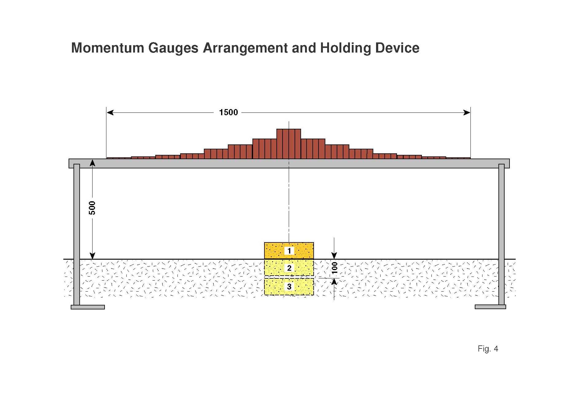
The author has performed diagnostic tests at the technical centre for weapons and ammunitions (WTD 91 in Meppen) with 5 kg DM12 B1 or PETN 87/13 cylindrical disc charges of L/D = 1/3 with 85 mm height and 255 mm diameter, to achieve the impulse density values in one central line crossing the rotational symmetric event [7]. Momentum gauges, which were arranged at constant distance or clearance of 500 mm above the sand ground were lifted up by the detonating charge (Figure 4). All the momentum gauges were simple steel blocks with 2.5 × 100 cm² cross section and different lengths, beginning with 150 mm, followed with 100, 75, 50, 25, 20, 10, and 5 mm. Their weights vary from 2.5 kg in the middle down to about 0.1 kg at the edges.
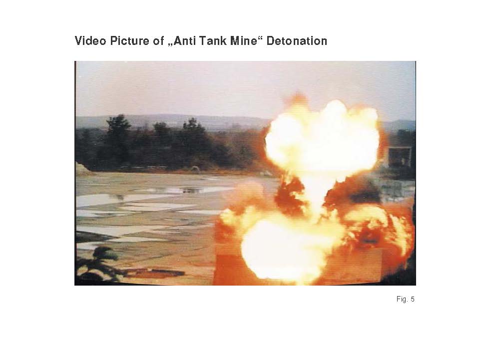
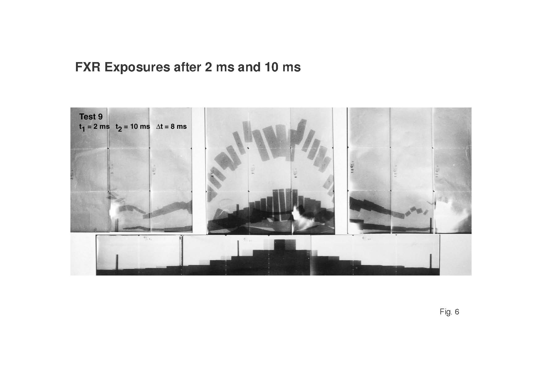
A standard video picture frame in Figure 5 shows already the axially focused or concentrated blast effect in the axis of a high-explosive charge disc. The velocities of the momentum gauges were measured by two flash X-ray exposures with 2 ms and 10 ms delay times after the detonation of the charge. Two 450 kV Scandiflash flash X ray equipments were used. A copy of the positions of the momentum gauges with their different length and therefore masses is presented in Figure 6. The achieved velocity v times their masses m gives their momenta M. The momenta M divided by the bottom surface of the momentum gauges (10 × 2.5 cm²) gives their impulse densities ID. The results of the three different firing positions of these charges, lying on the ground, level with the ground, and buried 100 mm deep in sand are compared in Figure 7.
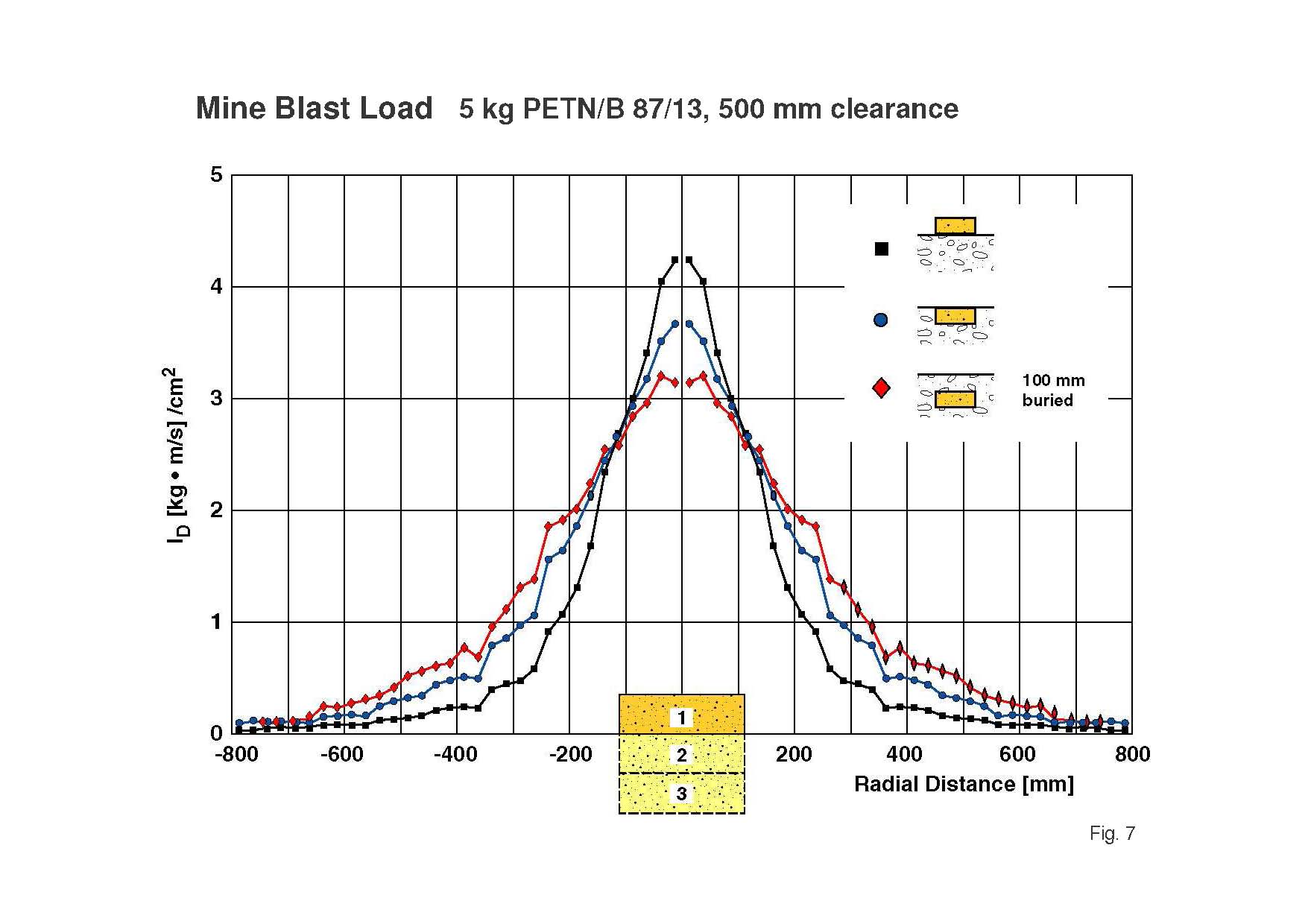
The maximum impulse density values are achieved along the charge axis. They are decreasing from the charge lying on the ground, which has the nearest distance to the momentum gauges, followed by the charge level with the ground at about 15% reduction, and finally to the charge buried 100 mm deep at about 25% reduction.
In a first simple consideration this can be explained by the increased distances from 465 mm to 535 mm and finally 635 mm from the mine’s centre of mass to the centrally arranged momentum blocks. The distance ratios are 465/535 = 0.87, which results in a 15% reduction and 465/635 = 0.73, corresponding to a 25% reduction.
But it can be seen in Figure 7, that the impulse density values of the ground-level and the buried charges are larger with increasing transverse distances or have less reduction compared to the charge lying on the sand.
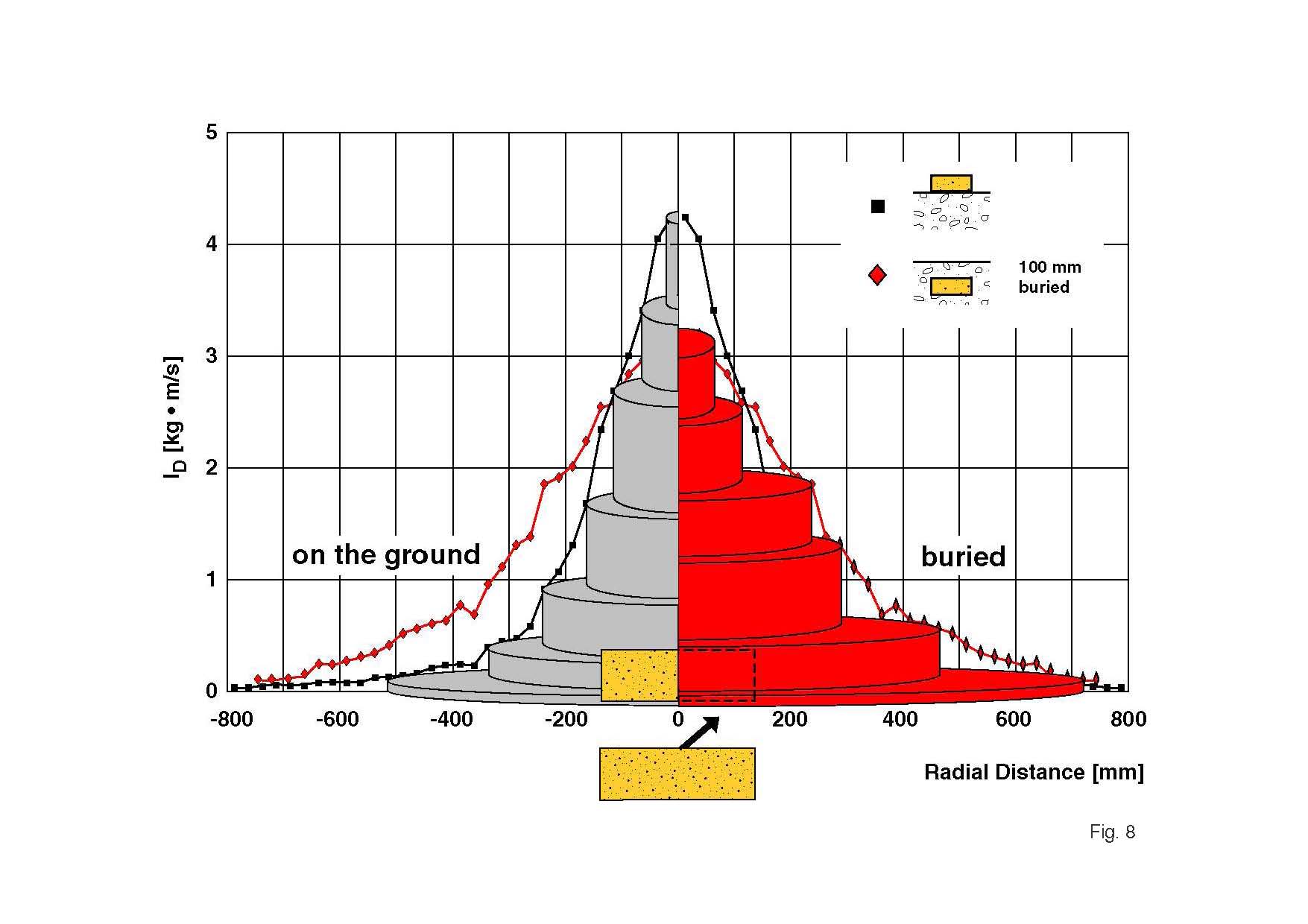
These impulse density values can be multiplied by the areas of the transverse ring zones to determine the forces per ring zone (Figure 8) where the base is significantly larger for the charges, buried in sand.
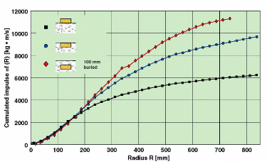
Now these ring zone values can be summed up, which gives the transferred momentum against a flat or belly plate as function of the transverse radius (Figure 9). The 100-mm deep buried charge gives an integral value larger by the factor of two compared to the charge lying on the ground at the transverse radius of 700 mm. The charge level with the ground lies just in between. These diagnostic results have to be taken into account to understand the statements of the author on the damage, caused by AT-mine detonations under normal vehicles and those of the military fleets.
Bulging test
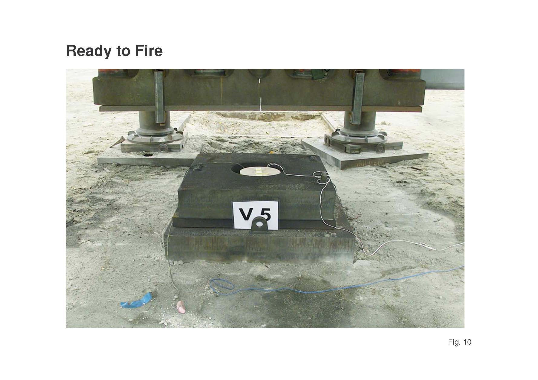
Besides the global load the goal was here to measure the displacement of a belly plate caused by an 8-kg cylindrical cast TNT-charge with 267 mm diameter and 89 mm length. This charge was embedded in a so-called steel pit, which guarantees a much higher reproducible blast load compared to the individual fountains of sand embedded charges (Figure 10). The charge also was 500 mm away from a 25-mm thick high-grade steel plate.
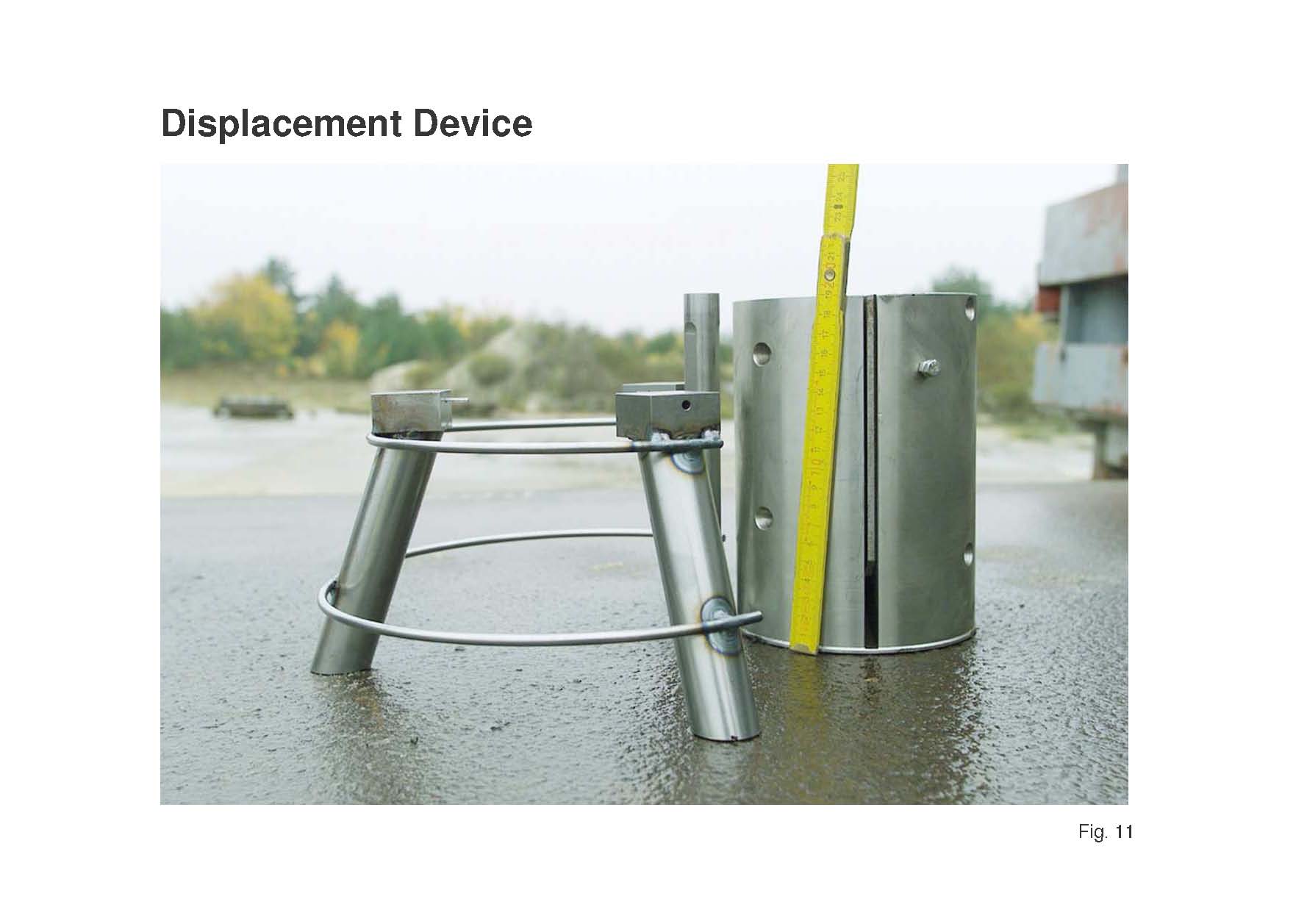
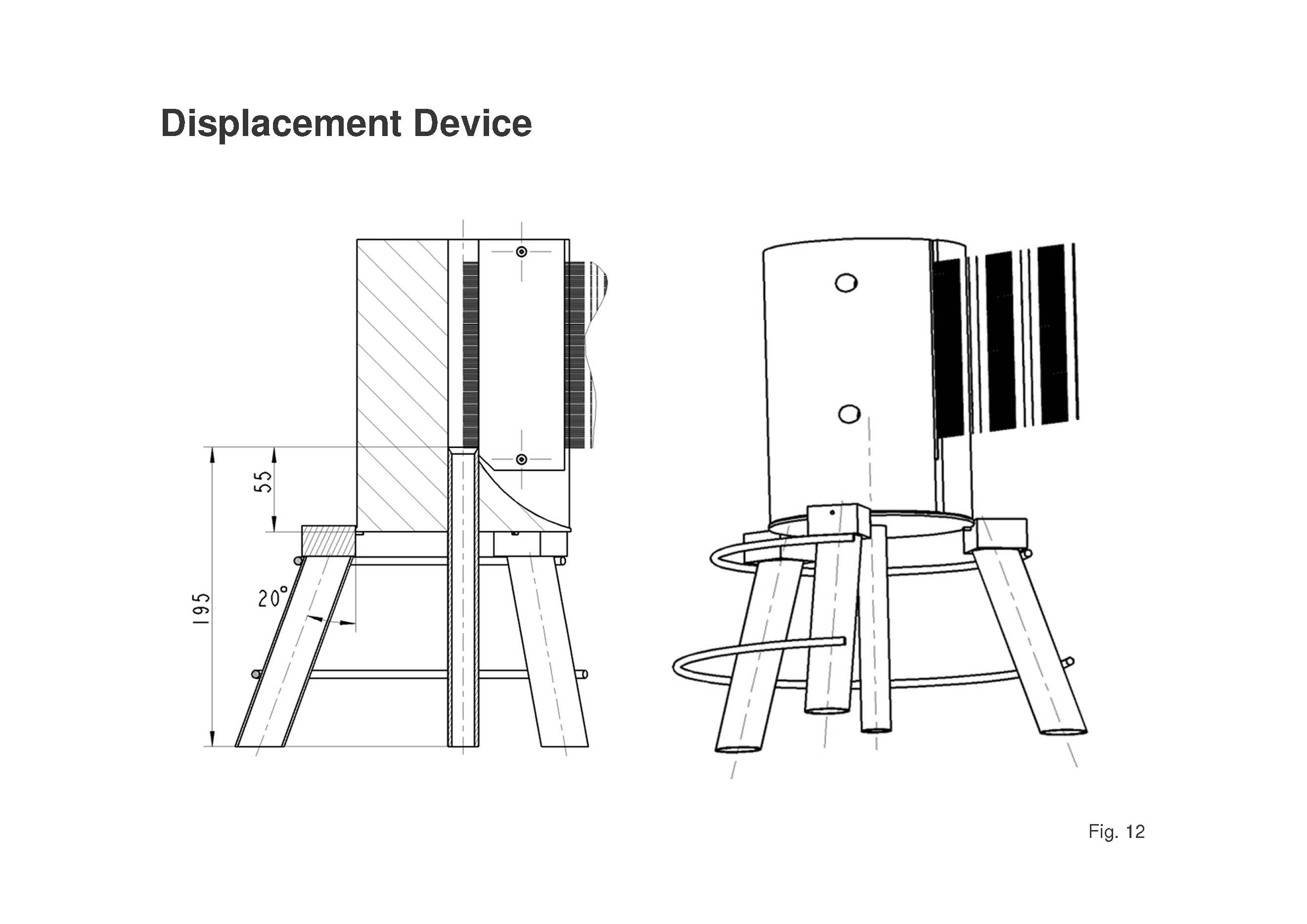
The displacement device consists of a heavy steel cylinder with a flat band cable fixed inside and a tube with a knife at its upper end which is inserted through an opening in the cylinder bottom. The steel cylinder is held on a tripod with three shear pins. The tripod and the tube are both placed on the plate.
The device functions as follows [8]: when the plate is accelerated by the blast load, both the tube and the tripod are accelerated by the blast load. The pin connections are dimensioned to break immediately, so that the heavy cylinder itself is not accelerated but is subject only to gravitation. The knife will then cut the wires of the flat band cable and from the cutting times and the position of the wires a displacement versus time function can be deduced.
Local
The displacement device [9] had a 20-kg steel cylinder which was held on a tripod with three shear pins of 2-mm diameter (Figure 11). The static cutting force of one shear pin was about 3 kN. In the dynamic case a force of 20 kN can be expected for all three pins. This leads to an acceleration of the 20-kg mass to 1,000 m/s² (a = F/m = 20,000 kg.m/s² / 20 kg = 1,000 m/s²). This force causes a movement of the 20 kg heavy drag mass after the equation s = 0.5×a×t² to 5 µm after 100 µs, which is a negligible value.
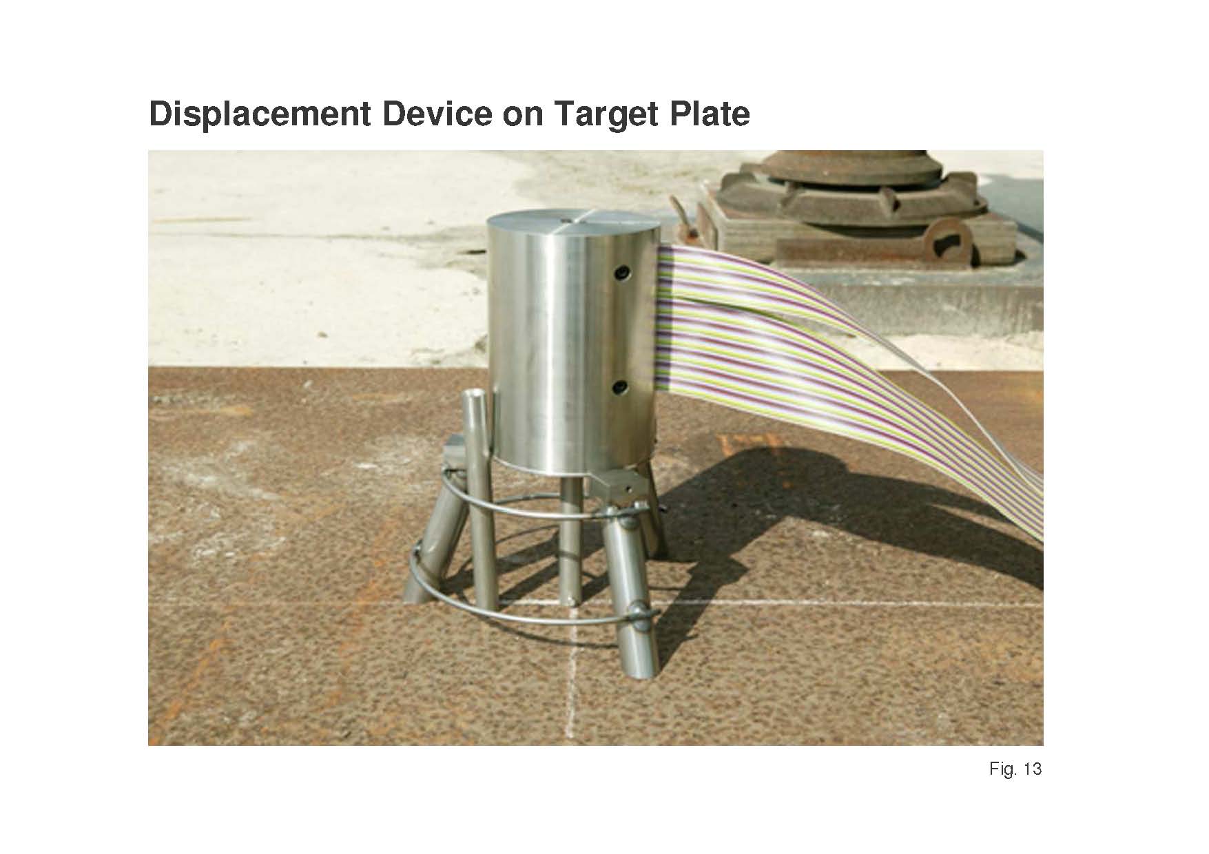
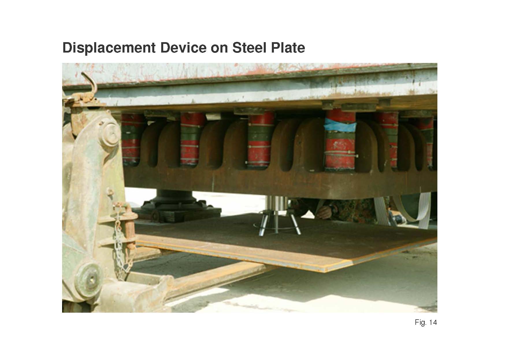
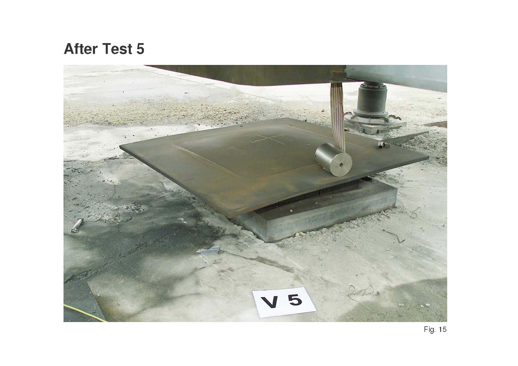
The drag mass had a hole of 20.2 mm diameter in the axis, in which a tube of 20-mm outside diameter and 16-mm inside diameter with a sharp knife edge on top was guided (Figure 12). This upward motion of the tube cut and electrically shorted the wires of a flat band cable. This flat band cable is tightened from the side in the drag mass. The signals were recorded with transient recorders. A tube was selected, so that the weight is small and the cut flat band pieces can fall inside and are out of the way. The displacement device together with the flat band cables, standing on the test plate, just before the plate is brought up to the test rig is shown in Figure 13. The plate with the described test set up is just positioned above the mine in Figure 14 and the deformed plate together with the drag mass after the test is visible in Figure 15.
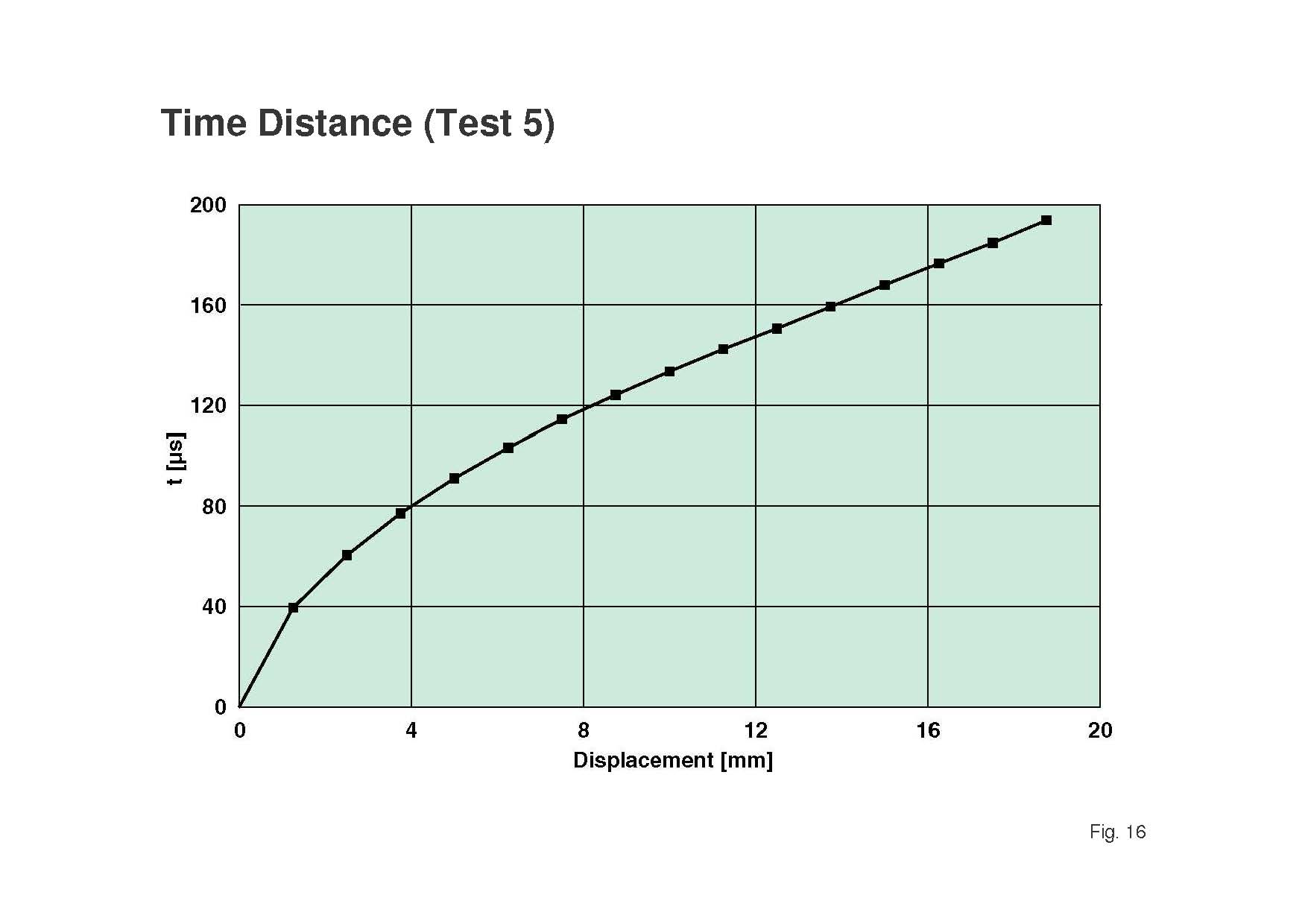
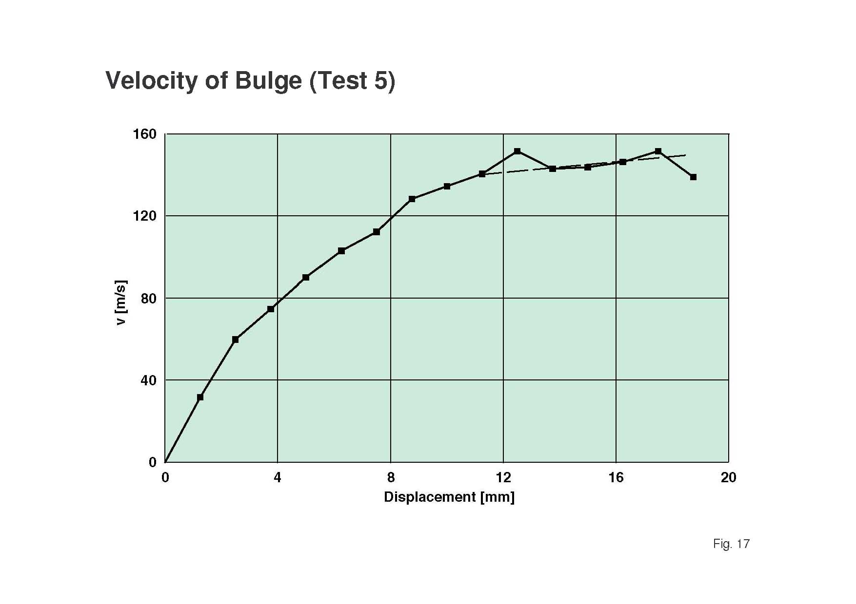
The separation of copper wires in the flat band cable was 1.25 mm. The shortening times as a function of displacements are presented in the diagram of Figure 16. The 1.25-mm spacing, divided by the time differences between two contacts, give their velocities (Figure 17), which increases over the first 16 mm to about 140 m/s. From this distance on it seems to have achieved the maximum value. The velocities as a function of time are shown in Figure 18, where are used the mean times between neighbouring contacts. The extrapolation to time zero is questionable. Surprising is a linear increase of velocity from 20 µs up to 140 µs, which means constant acceleration over this time period. The acceleration is roughly constant at 106 m/s² under this test condition.
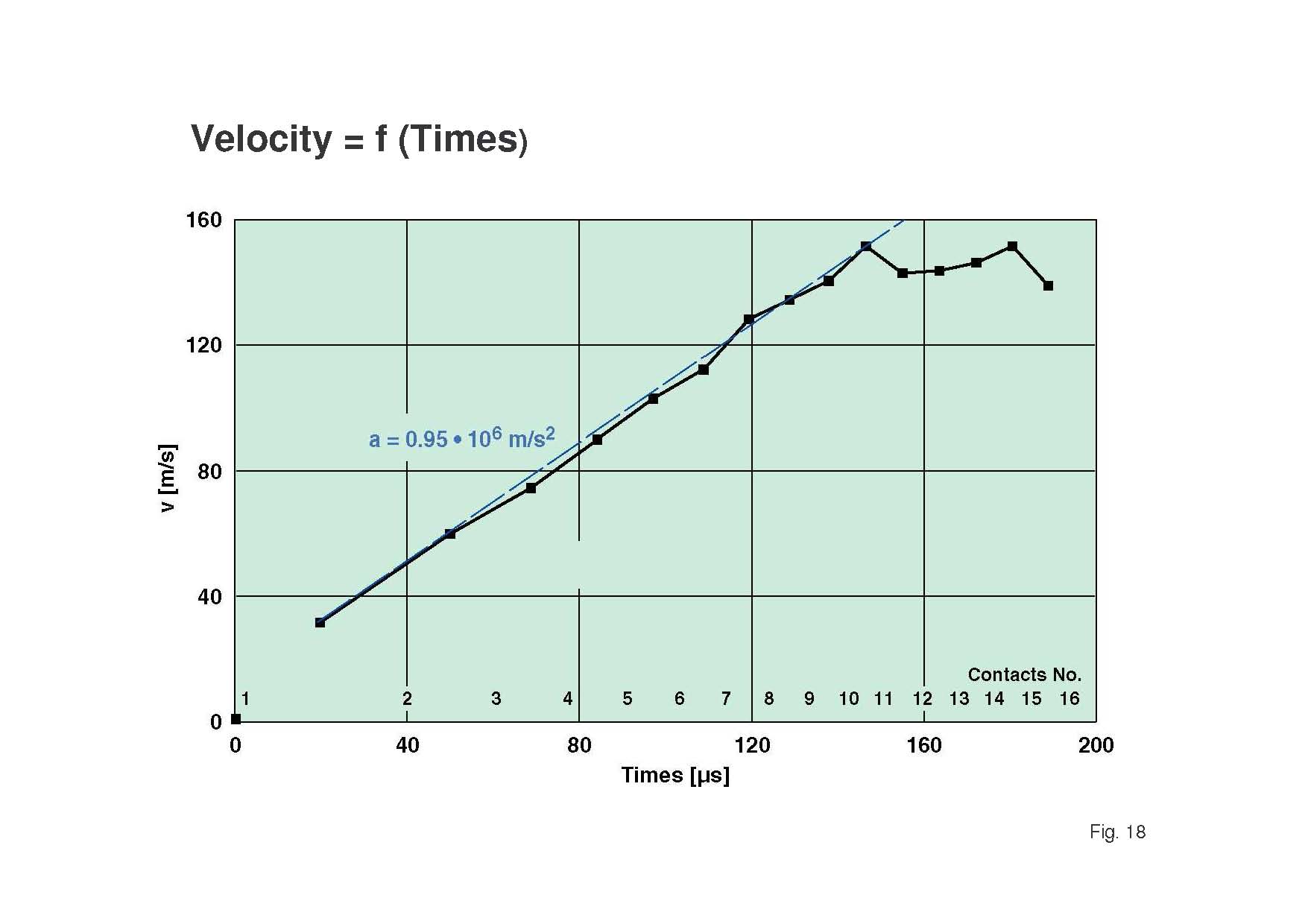
In repetition the high acceleration of 106 m/s² or 100,000 g acts over a time period of about 150 µs, respectively over a displacement distance of 14 mm. The further ongoing bulging of plate is mainly caused by inertial forces of the accelerated moving plate.
Contact condition
AT mines can detonate under the wheels or the tracks of vehicles or under the belly plate (Figure 19). These are two different load cases, which should be separately discussed. The maximum local load on wheels or tracks is achieved if the mine is in direct or close contact to these components. Any horizontal shifting of the buried mine from completely covered to partially covered by the tracks will reduce the load. But the power is generally many times larger than the threshold values of wheels or tracks, even if the high explosive charge is only partially lying under the wheel or track. The additional damage to the vehicle depends on whether the charge is positioned partially outside or inside the hull. Besides the damage to the mobility of the vehicles some damage will also be achieved against the hull structure depending on factors such as charge height and clearance height.
Local blast
Normally the bigger mine threat is the detonation between wheels and tracks under the belly plate. Single mines are typically flat discs with a thickness to diameter ratio of L/D = 1/3. Such high explosive discs, when detonating in air, give in the close field along the charge axis a very concentrated, focused blast wave and also a strong radial blast ring, whereby in the diagonal or bridge-wave directions in the angles between 15° to 75° the impulse densities have much lower values than 1/10 compared to the other directions (Fig 20) [7]. This local force along the centre line or charge axis has a maximum impulse density value if the charge is lying on the ground, as described before. The reason is the nearest distance of the HE-charge to the target and no sand layer is damping the focused blast wave.
This strongly focused blast wave is dangerous, if the scaled distance Z (distance R divided by the cubic root of the charge weight W1/3) is smaller than 0.5 m/kg1/3. An 8-kg charge at 0.5 m distance has a scaled distance of Z = 0.25 m/kg1/3. This localised force is deforming the belly plate, which can get a dynamic or elastic deformation of 150 mm, which can spring back to about 100 mm static or plastic deformation on a good ductile steel armour plate depending beside the material properties on the dimensions of the plate and its boundary conditions (Figure 21). But this dynamic deformation achieves velocities of 150 m/s and this is propelling any devices and materials, which are lying on the plate. The extremely fast load is also very critical against legs of crew members. To reduce this locally occurring extremely fast threat, a double plate is now often inserted in mine-resistant vehicles. The load strength depends on a number of factors—the major ones are:
- charge mass;
- charge geometry;
- initiation point in the charge;
- distance or clearance to belly plate;
- underground conditions, if lying on or in the sand;
- sand cover;
- belly plate thickness; and
- dynamic yield strength and elongation.
Especially high-strength steel plates are used for good resistance with at least some ductility or stretching possibilities.
The buried charge has a lower peak impulse at the centre, but its higher shoulder values are also supporting larger plate deformations under this condition.
Global forces
Besides these very high impulse density values of 1 N•s/cm² up to 10 N•s/cm² over small area it comes up to the global forces, acting against the ground area of the vehicle (Figure 22).
As already shown, the impulse density drops very fast down with the radial distance to the charge axis. But the areas of the discrete ring zones are increasing and therefore the ring momenta are remarkably increasing (see Figure 8). The integral value is increasing nearly by a factor of two from the charge lying on the ground over the charge level with the ground to the charge buried 100-mm deep in sand (see Figure 9). The strongly localised impulse for the charge lying on the sand is now much more radially dispersed by the sand that is pushed up by the buried charge. Sand is a better impulse transfer medium over some distance compared to the gaseous products of explosives, which have lower densities. This global momentum is transferred to the vehicle in a time range of less than 1 ms for unburied charges and in 3 ms to 4 ms for buried charges, mainly depending on the ground clearance and the vehicle geometry.
Shock wave and acceleration loads
There are two different physical load mechanisms caused by a detonating AT mine. One is the imparted shock load by the blast wave in air. The second one is the extremely high acceleration of the total vehicle, which also travels from the bottom through the steel frame of the vehicle with sound speed in steel of roughly 6 km/s.
Shock waves by air blast
A 1-kg spherical charge introduces roughly 100 bar in a steel plate at 1 m distance as reflected shock wave, corresponding to 10 MPa, which looks large. But if the units of steel strength in kp/mm² or N/mm² are taken, then these values look really low with 1 kp/mm² or 10 N/mm².
In the charge axis of an 8-kg cylindrical mine charge with a L/D = 1/3 a maximum reflected pressure of 1,000 bar = 100 MPa or 10 kp/mm² or 100 N/mm² will be introduced, which is also a factor lower compared to RHA material strength at static testing conditions. In a dynamic case these values can increase up to the factor of three. This shock load is not too large and will be additionally significantly reduced over some travelling distances and corners etc. No direct damage will occur from shock load transferred by the air blast wave.
Acceleration load
The global impulse, transferred momentum or impulse of a mine, detonating beneath the belly plate, is in the range of 10.000 N•s to 20.000 N•s (see Figure 9). The imparted acceleration to the vehicle can be calculated with the simple equation: a = F/m, where a is the acceleration in m/s², F the force in kg•m/s², and m the global mass of the vehicle in kg. The force F is the quotient of the impulse I and impulse duration t (F = I/t) The following table gives the appearing accelerations for the impulse of 20,000 Ns, acting around 200 µs at the vehicle, which gives a force of 100,000,000 N.
Acceleration a in m/s² for different vehicle masses m in tons:
| m (in tons) | 1 | 2 | 5 | 10 | 20 |
|---|---|---|---|---|---|
| a (km/s²) | 100 | 50 | 20 | 10 | 5 |
These are mean values for the acceleration over a time period of 200 µs, but the forces, correlated to the peak impulses can be much larger.
These extreme accelerations cause very high load values and are a great threat for breaking off screws, bolts, and welding of so-called discrete masses.
But damage by these acceleration forces can be remarkably reduced by “soft” holding designs, because the load acting times are extremely short and therefore displacements of separated masses are very small.
The shift, as a function of acceleration and load acting time t is given by the following equation: s = 0.5×a×t².
Taking as an example a 5-t vehicle with 20,000 m/s² acceleration over a time period of 200 µs gives only a displacement of 0.4 mm (s = 0.5×2×104×4×10−8 = 0.4 mm).
One has to use connections, which allow such shifting without brittle breaking; then these extremely large drag forces by the high accelerations will cause damage.
Summary and conclusions
AT mines can produce different damage mechanisms, depending on the location on which they act on the vehicle. In direct or very close contact to the wheel or track an overmatched local damage will be caused, but with less global forces on the chassis. Beneath the belly plate two different loads happen: strong bulging of the belly plate from the focused blast, and as global forces for lifting up the whole vehicle or some sections. Here very large acceleration forces occur, which leads to separations of individual or singular masses.
The shock wave load by the imparting blast wave is minor compared to the acceleration or drag forces, which are many magnitudes larger. But these can be significantly reduced, if “smooth” connections are used on “separated” masses in the vehicles.
The surprising result is that, if the acting time is increased by a factor of two, then the force F and the acceleration are decreased by the same factor, but the displacement is increased just by this factor of two. More damage should be expected by longer acting times of the impulse, because the forces are very far above the threshold values and can be reduced for more than one magnitude, but this would increase the displacements by the same factor.
The vehicles will be mostly not pushed up just in the centre of gravity. They will be mostly asymmetric attacked, which cause larger loads on the nearer sections. AT mines are mostly detonating in the front part, and then the acceleration in the front will be typically larger by a factor of two. If the AT mine detonates beneath a wheel or track, then an additional side lifting will happen. But under these conditions, wheel and track are stripped off and less force and momentum is transferred to the chassis compared to a detonation under the belly plate.
Acknowledgement
I would like to thank J. Kiermeir and D. Vinckier of company CONDAT for very useful discussions and Frikkie Mostert of CSIR in SA for his comments and corrections on this paper.
References
[1] R. Ogorkiewicz, “Mine Protection of AFV’s” in the course Fundamentals of Armoured Protection, Cranfield University 28−30 April 2008.
[2] F. Dosquet, “Overmatch Analysis as Enhancement for conventional Protection Analysis”, 3rd European Survivability Workshop, Toulouse, Trance 2006
[3] F. Dosquet and C. Lammers, “Vehicular Protection against Blast IED”, 4th European Survivability Workshop, Malvern, UK, 2008.
[4] F. Dosquet, "Load Transfer Model for Human Vulnerability Applications", 4th European Survivability Workshop, Malvern, UK, 2008.
[5] M. Held, “Momentum Distribution of Anti-Tank Mines”, 20th International Symposium on Ballistics, Orlando, Florida Sept. 2002.
[6] M. Held, “Ermittlung der Blast-Wirkung von Panzerminen mit der Momentum-Methode”, Wehrtechnisches Symposium bei militärischen Landfahrzeugen, BAWVT Mannheim, Germany, 2002
[7] M. Held, “Blast Contour of Cylindrical Charges with Different Length to Diameter Ratios”, 11th International Symposium on Interaction, Mannheim, Germany, 2003.
[8] J. Kiermeir, The author has used the idea of Mr. J. Kiermeir to take a heavy drag mass for this task.
[9] M. Held, P. Heeger ,and J. Kiermeir, “Displacement Device to Measure the Acceleration of the Bulge of RHA Plates under Anti Tank Mine Blast”; 22nd International Symposium on Ballistics, Vancouver, CA, pp. 995−1000, 2005.