
Volume 11, Number 2, July 2008
Flat-Fire Aerodynamic Jump Performance Of Projectiles Fired Sidewise From A Helicopter
- 1 Laboratory of Firearms and Tool Marks Section, Criminal Investigation Division, Captain of Hellenic Police, 11522 Athens and postgraduate student of Fluid Mechanics Laboratory, University of Patras, 26500, GREECE.
- 2 Postgraduate student of Fluid Mechanics Laboratory, University of Patras, 26500, GREECE.
- 3 Assistant Professor, Mechanical Engineering and Aeronautics Department, University of Patras, 26500 Patras, GREECE.
- 4 Ex-Professor of Mechanical Engineering and Aeronautics Department, University of Patras, 26500 Patras, GREECE.
Abstract
This study investigates the effect of the aerodynamic jump phenomenon on the flat-fire free flight trajectory motion of projectiles launched horizontally at various angles from low-speed helicopters. The ammunition used was the 30-mm-diameter XM788 projectile type fired from M230 machine automatic cannon. Modified linear 6-DOF flight simulation modelling was applied to the free-trajectory prediction of spin-stabilized projectiles. This analysis includes variable coefficients of the most significant aerodynamic forces, moments, and Magnus effects, which have been taken from official tabulated database, in addition to gravity acceleration. During the entire atmospheric flight the coupled epicyclic pitching and yawing motion analysis is taken into account.
Introduction
The motion of a projectile can be separated into two general regions [1]: the free-flight (FF) region, and the launch disturbance (LD) region (prior to FF). The end of the LD region marks the beginning of the FF region, where the phenomenon known as aerodynamic jump occurs.
The trajectory deflection caused by aerodynamic jump on a .30-calibre machine gun bullet was first addressed in 1943 by Sterne [2]. This reference, written by mathematicians who were tasked with generating firing tables for the machine guns, used sidewise fire from high-speed airplanes. Various authors have simulated the aerodynamic jump phenomenon caused by aerodynamic asymmetry [3], lateral force impulses [4], and non-linear forces and moments [5].
A modified linear flight dynamic model with variable aerodynamic coefficients depending on Costello’s theory [6,7] is applied for the free-flight rapid-trajectory prediction. The computational results of the above analysis have already been verified for full six-degree-of-freedom (6-DOF) trajectory simulations for large (105-mm HE M1) and small (7.62-mm bullet) spinning projectile types [8]. In the present work, it is applied for the atmospheric free-flight motion of 30-mm XM788 projectile [9] fired sidewise from a low-speed helicopter. The coupled pitching and yawing motion [10–12] is obtained for the whole atmospheric path taking into account the initial aerodynamic characteristics and firing yaw angle effects.
This paper extends the work of McCoy [13], which examined the aerodynamic jump for projectiles fired perpendicular to the aircraft line-of-flight. A new engineering correlation is proposed for the flat-fire launched disturbance due to aerodynamic jump performance firing at different angles relative to the helicopter’s flight path. This formulation is based on the initial sideslip (yaw) angle between the total muzzle velocity vector and the firing projectile axis.
Projectile model
The present analysis considers a type of 30-mm cartridge [9]. The XM788 target practice (TP) has a blue painted projectile with white markings. The inert/solid projectile is a three-piece assembly consisting of steel body with cavity, rotating band, and aluminium nose piece. The cartridge case is aluminium.
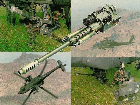
Basic physical and geometrical characteristics data of the above-mentioned 30-mm cartridge with type XM788 illustrated briefly in Table 1. This projectile can be fired from a M230 machine automatic cannon on the ground, or mounted on a low-speed helicopter, as illustrated in Figure 1.
Atmospheric flight model
The projectile can be modelled as rigid body possessing six [8,14,15] DOF) including three inertial position components of the system mass centre as well as the three Euler orientation angles.
| Characteristics | XM788 cartridge |
|---|---|
| Reference diameter, mm | 29.92 |
| Total length, mm | 199.77 |
| Total mass, kg | 0.329 |
| Axial moment of inertia, kg·m2 | 3.302 × 10⁻⁵ |
| Transverse moment of inertia, kg·m2 | 1.743 × 10⁻⁴ |
Two main coordinate systems are used for the computational approach of the atmospheric flight motion. The first is a plane (inertial frame, IF) fixed at the ground surface, with centre O1 at the projection of the firing point onto the ground surface, as depicted in Figure 2. The second is a no-roll rotating coordinate system that is attached to, and moving with, the projectile’s centre of mass O2 (no-roll-frame, NRF, φ = 0) with XNRF axis along the projectile’s axis of rotational symmetry positive from tail to nose (Figure 2). The YNRF axis is perpendicular to XNRF lying in the horizontally plane. The ZNRF axis is oriented so as to complete a right-hand orthogonal system.
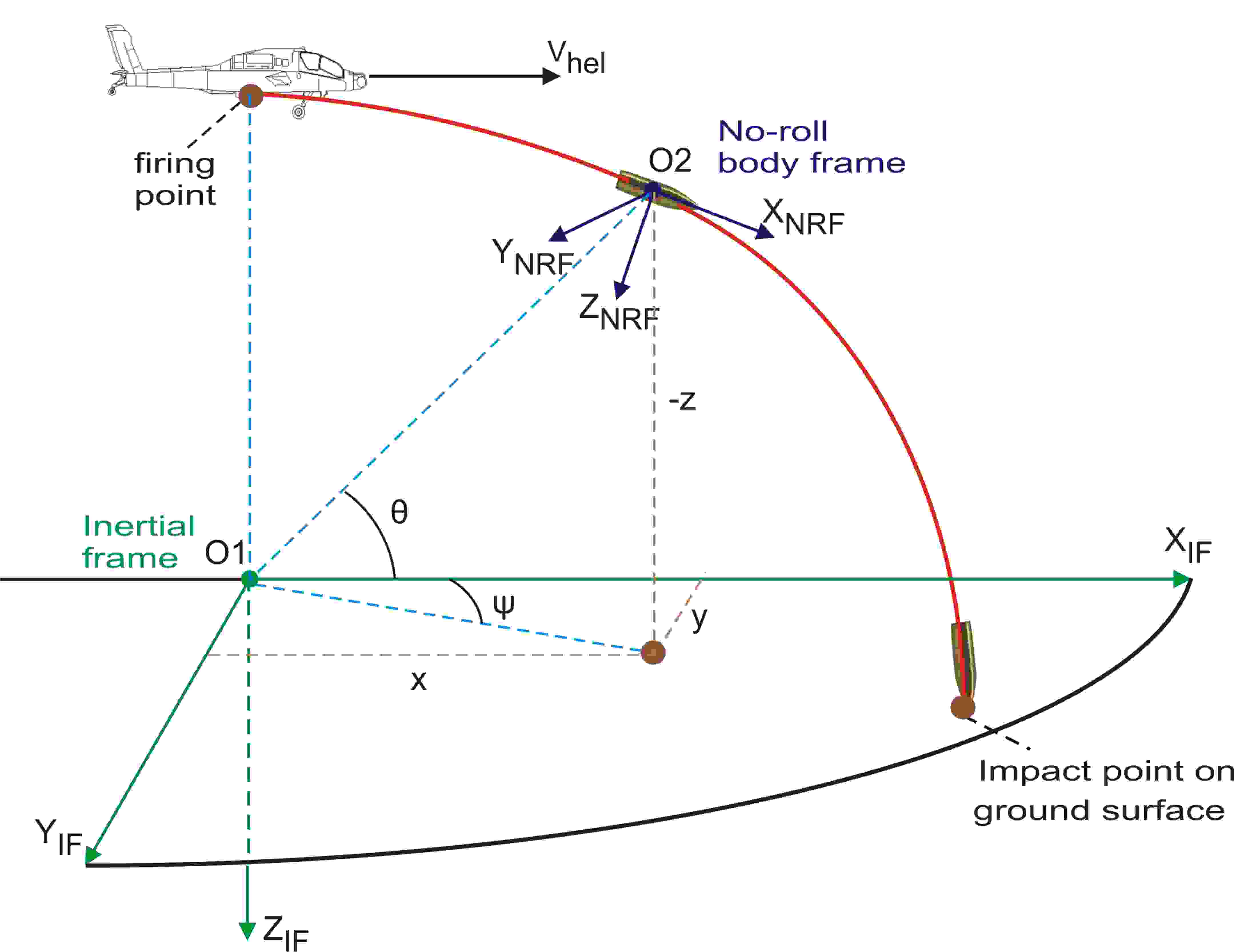
The twelve state variables x, y, z, φ, θ, ψ, , , , , and are necessary to describe position, flight direction, and velocity at every point of the projectile’s trajectory through the atmosphere. Introducing the components of the acting forces and moments expressed in the no-roll-frame with the dimensionless arc length l measured in calibres of travel, as an independent variable:
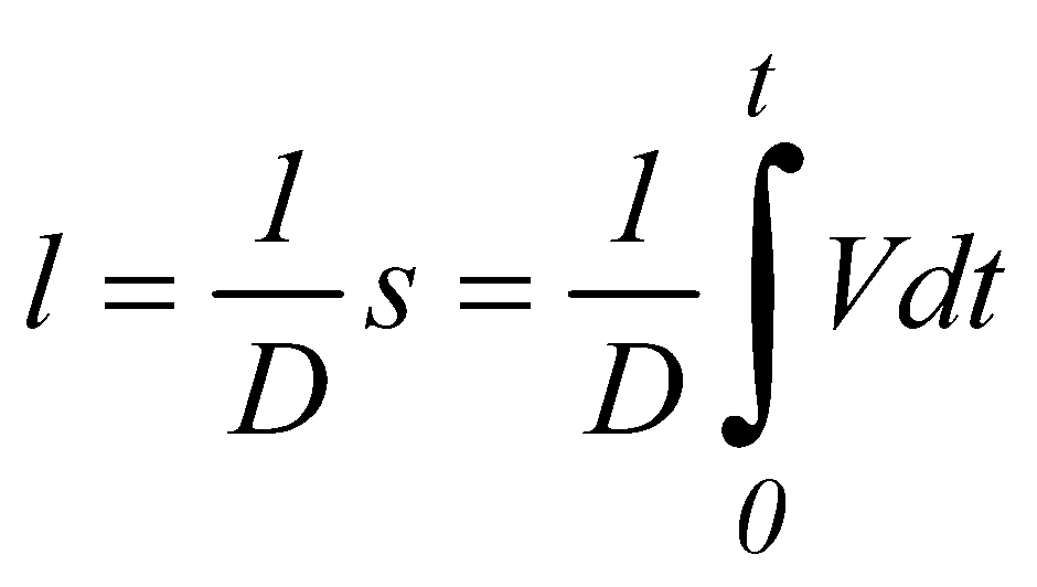
the following modified linear no-wind equations of motion are derived:


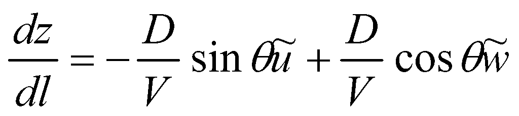
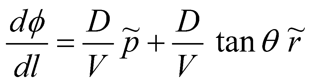
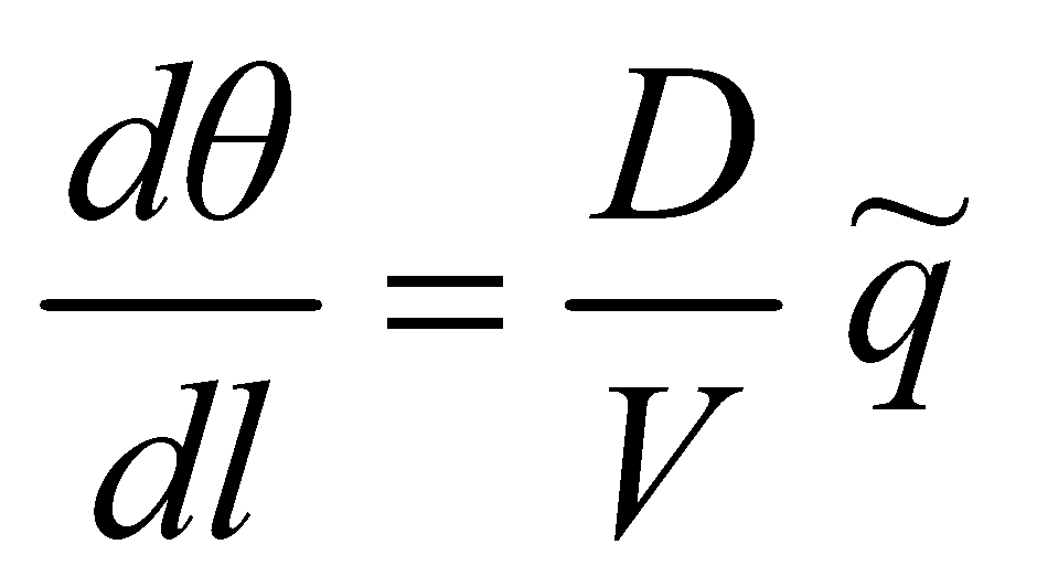
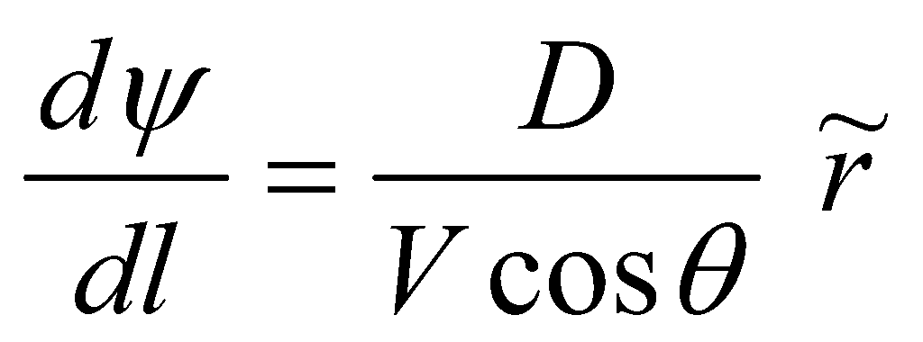


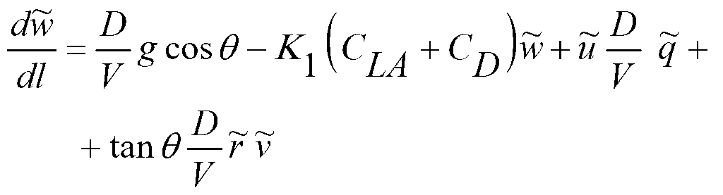
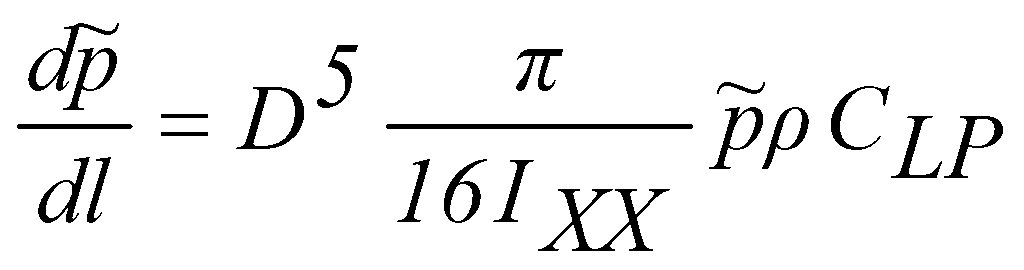
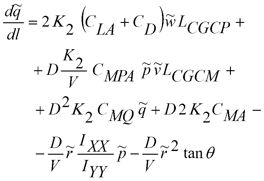
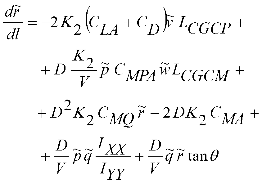
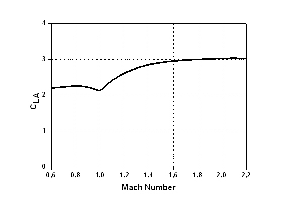
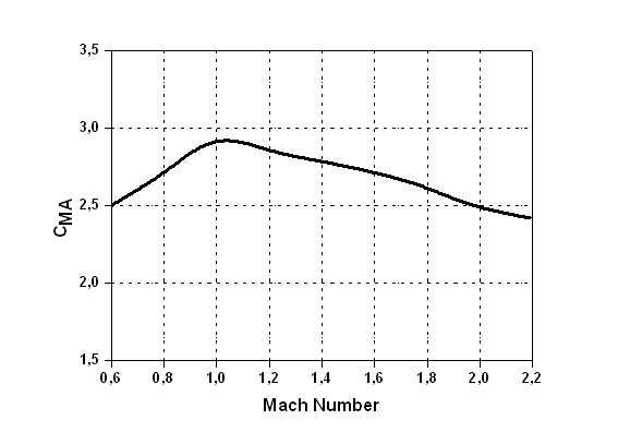
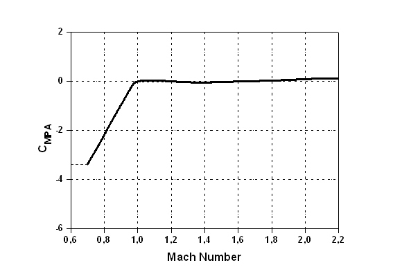
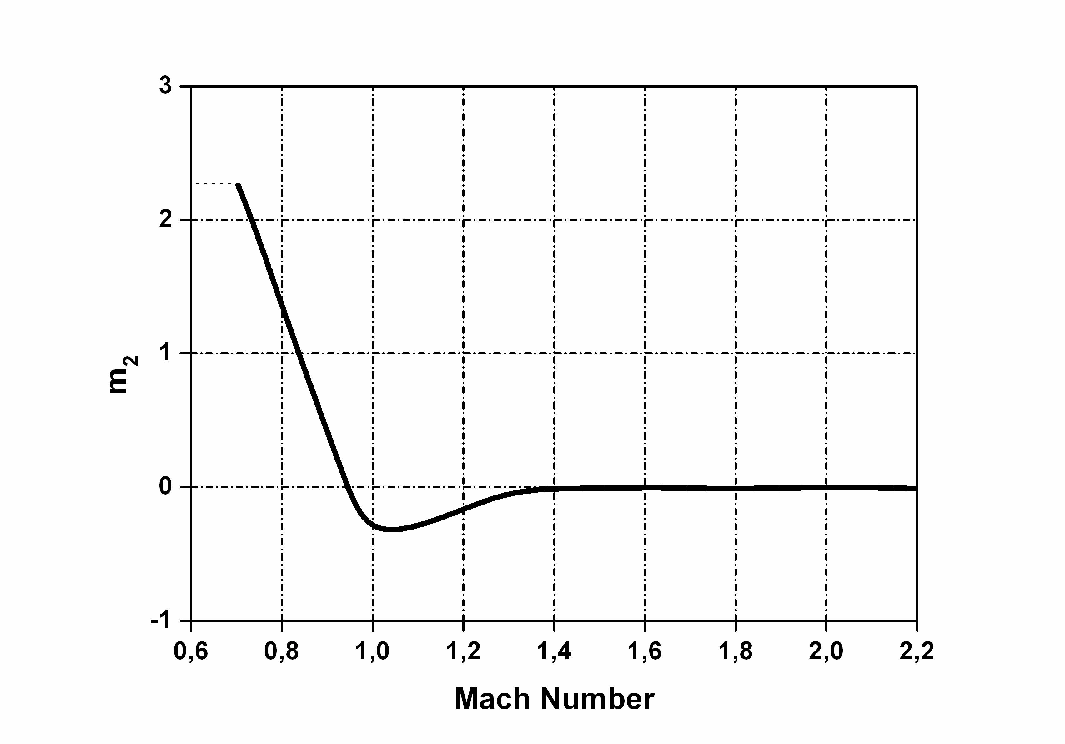
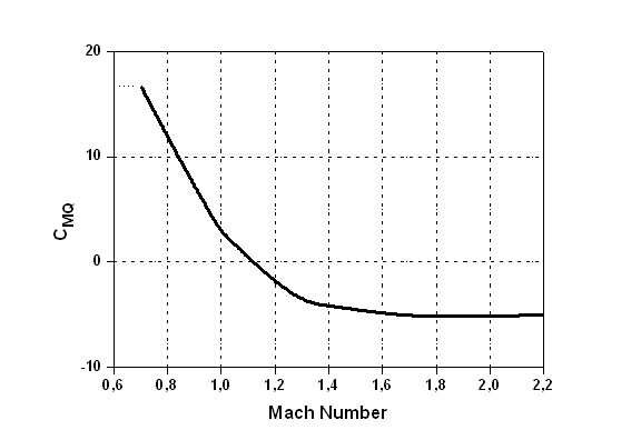
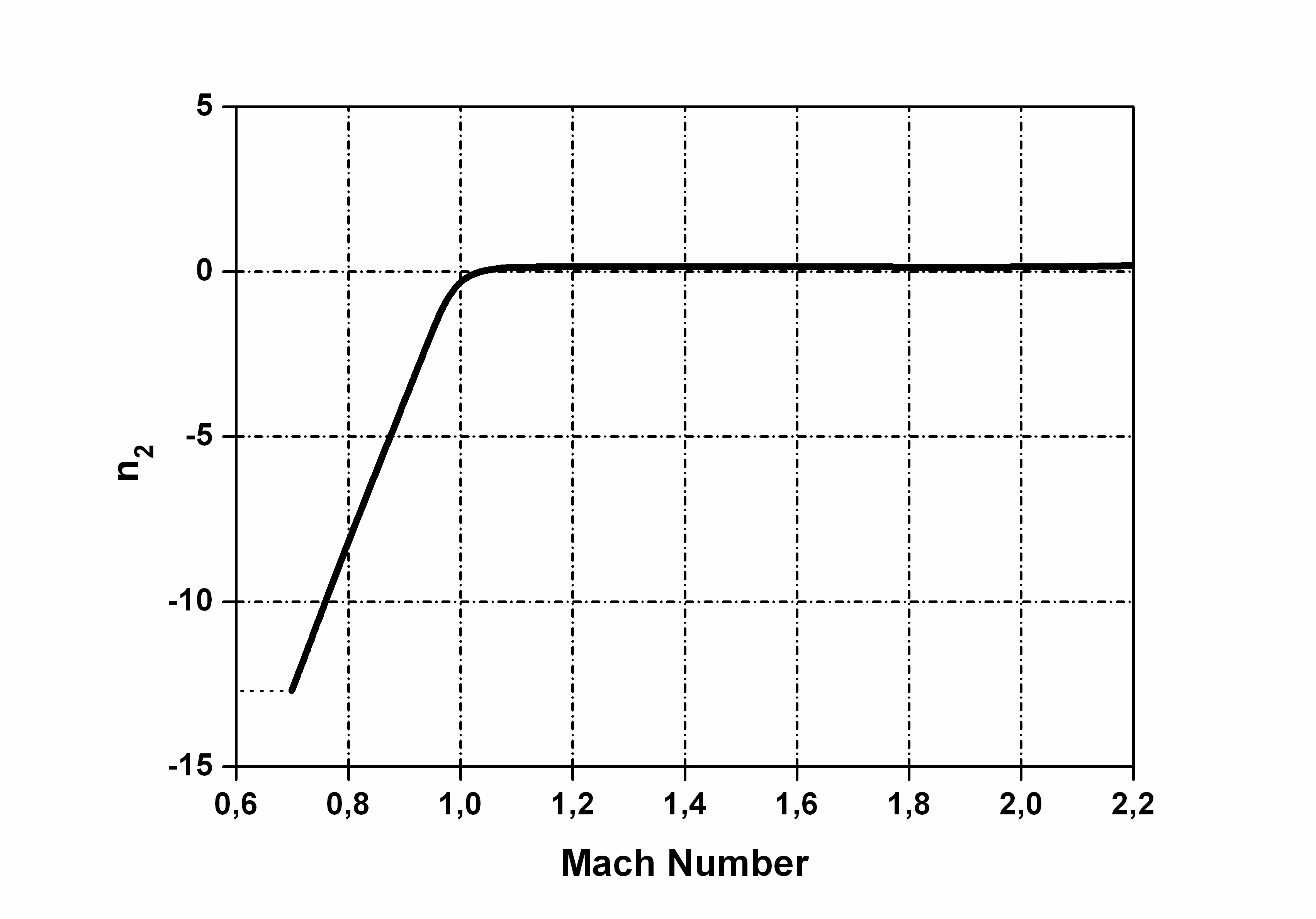
The aerodynamic coefficients CD, CLA, CMPA, CMQ, CMA used in this model are projectile-specific functions of the Mach number and total angle of attack variations for the examined type 30-mm XM788 [9], as listed in the Appendix to this paper. On the other hand, the roll-damping aerodynamic coefficient CLP does not varying significantly with Mach number and therefore is given the small negative constant mean value of CLP = –0.015 for the main part of the projectile firing-to-target motion.
The projectile dynamics trajectory model consists of twelve first-order ordinary differentials, (2) to (13), which are solved simultaneously by resorting to numerical integration using a 4th-order Runge-Kutta method, and regard to the 6-D nominal no-wind atmospheric motion.
In these equations, the following sets of simplifications are employed: The aerodynamic angles of attack α and sideslip β remain small (< 15°) for the main part of the atmospheric trajectory [8]:

In addition, the projectile is geometrically symmetrical IXY = IYZ = IXZ = 0, IYY = IZZ and aerodynamically symmetric. With the afore-mentioned assumptions, the expression of the distance from the centre of mass CG to the standard aerodynamic centre of pressure CP is simplified.

The Magnus force components are small in comparison with the weight and aerodynamic components, and so they are treated as negligible.
In order to have a stable flight for spin-stabilized projectile trajectory motion, the initial spin rate prediction at the gun muzzle in the firing site is important. According to McCoy’s method [13], the following form is used:

where is the total firing velocity, is the rifling right-hand twist rate of the M230 machine gun with helix angle of 6°30' (27.6 calibres/turn), and D is the reference diameter of the projectile type.
Aerodynamic jump deflection
For modern high-velocity, small yaw, flat-fire trajectories the tangent of the deflection angle due to aerodynamic jump phenomenon [1, 13] is given by the following expression:
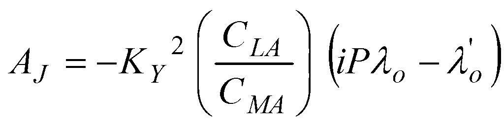
where is the initial complex yaw (or sideslip) angle:
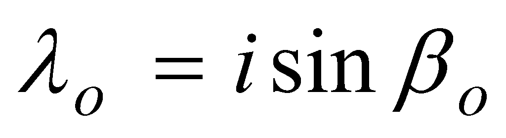
and the initial complex yaw rate or tip-off rate (rad/calibre).
If a spinning projectile like the 30-mm XM788 has an initial yaw , but no significant , (17) reduces to the simpler form:
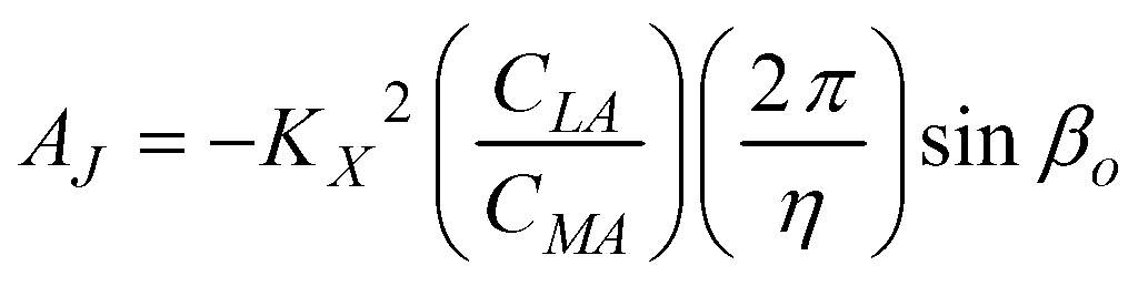
where is the non-dimension axial moment of inertia, and and are lift and overturning aerodynamic coefficients of 30-mm XM788 projectile at the firing point, depending on the initial launch Mach number.
Firing sidewise with at an angle ω relative to the helicopters flight path motion (Figure 3), the total initial muzzle velocity of the projectile is:
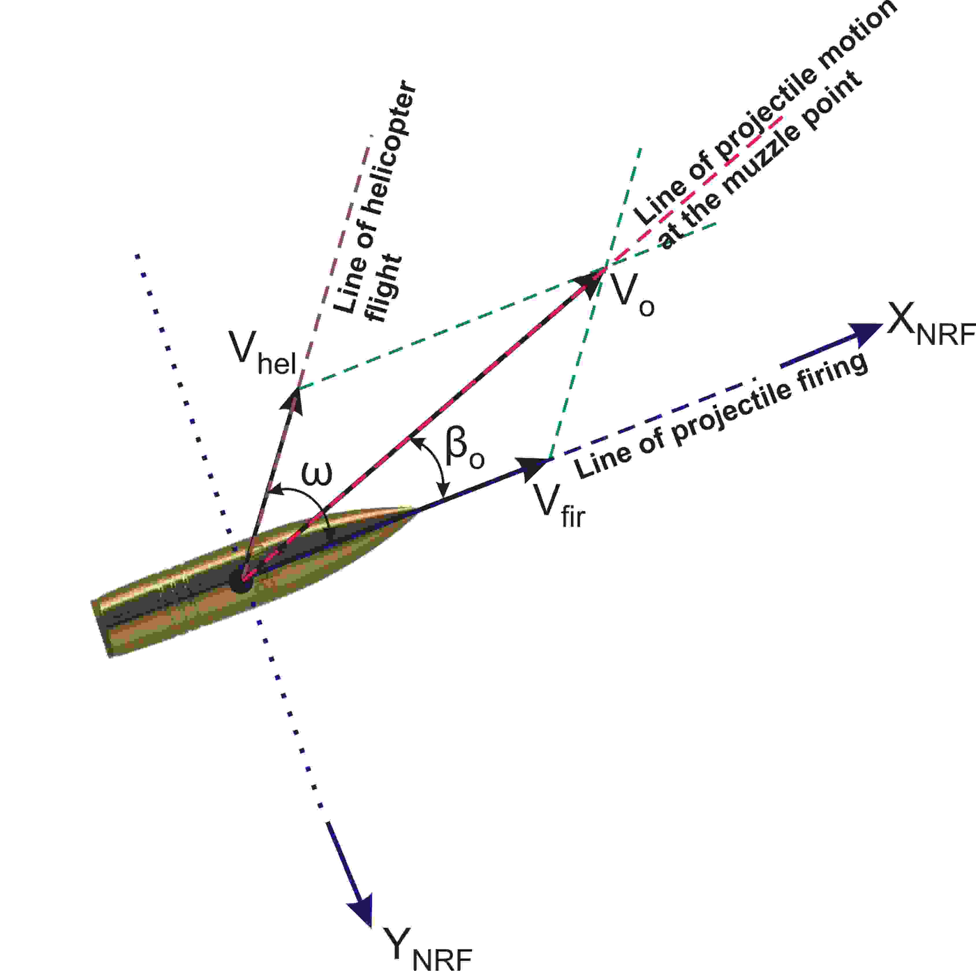

The directed angle, , as illustrated in Figure 3, from the shifted velocity vector to the projectile’s spin axis (firing line) is a pure sideslip (yaw) angle (zero pitch component) expressed in the form:
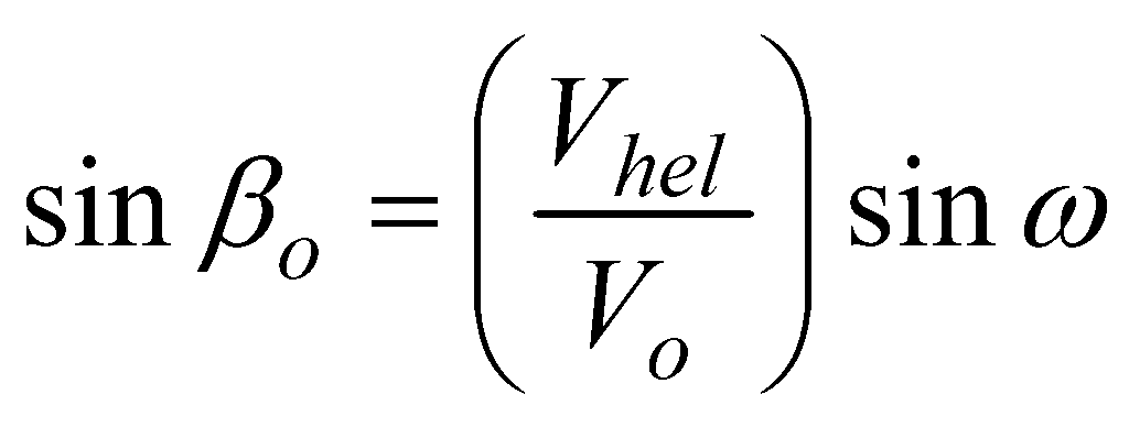
Combining (19) with (21) gives the following engineering correlation formula for the aerodynamic jump performance for flat-firing sidewise from low-speed helicopters:
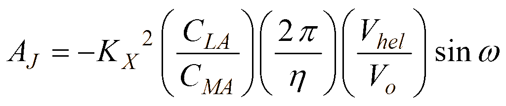
(21) states, that if the physical, geometric, and aerodynamic characteristics of the projectile and the initial muzzle firing and helicopter velocities remain constant, maximum AJ occurs when the projectile firing perpendicular (ω = 90°) relative to .
The vertical deflection Z to target impact point produced by the aerodynamic jump performance due to initial sidewise flat-fire is:

where Z is directed upward (negative ZIF-axis direction) in the case of right-hand spin (positive rifling twist rate).
Computational simulation
The 6-DOF non-thrusting and non-constrained flat-fire atmospheric trajectory for the present specific analysis of the 30-mm XM788 projectile motion is simulated. Horizontal fire (zero degrees quadrant elevation angle) is assumed firing to the right-hand side at three different angles (10°, 20°, and 30 ) with 805 m/s relative to the helicopter’s low velocity of 100 knots (51 m/sec).
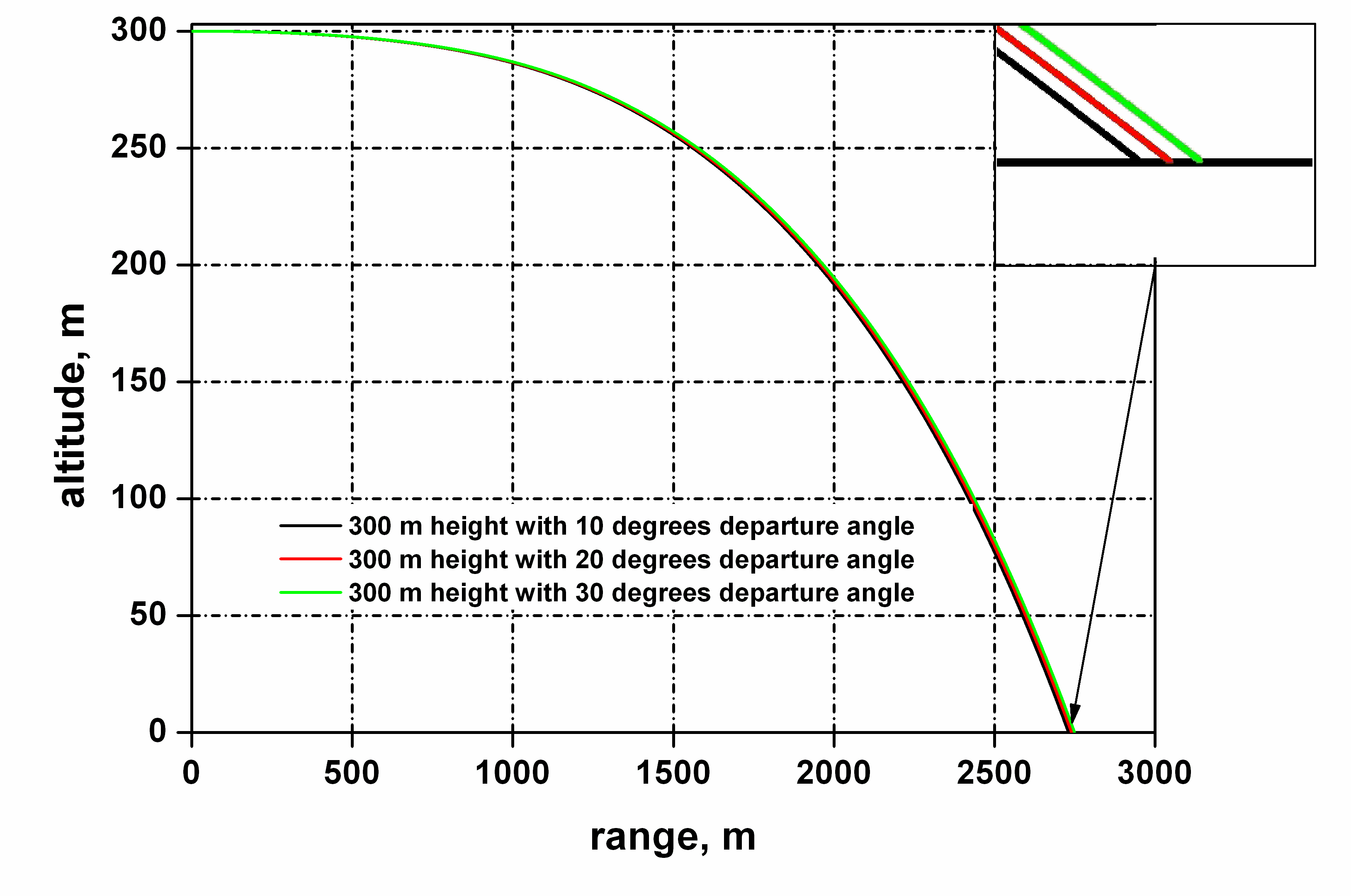
In Figure 4, a modified linear flight atmospheric model with variable aerodynamic and Magnus coefficients is applied for the 30-calibre projectile firing at 300-m height while the wind effects are neglected. The target impact point predictions of the above trajectories, as shown in the additional zoomed picture in the same Figure 4, are 2,797 m, 2,794 m and 2,789 m at firing angles 10°, 20°, and 30°, respectively. Few metres difference in the final target shooting area is significant for a small projectile like 30-mm XM788.
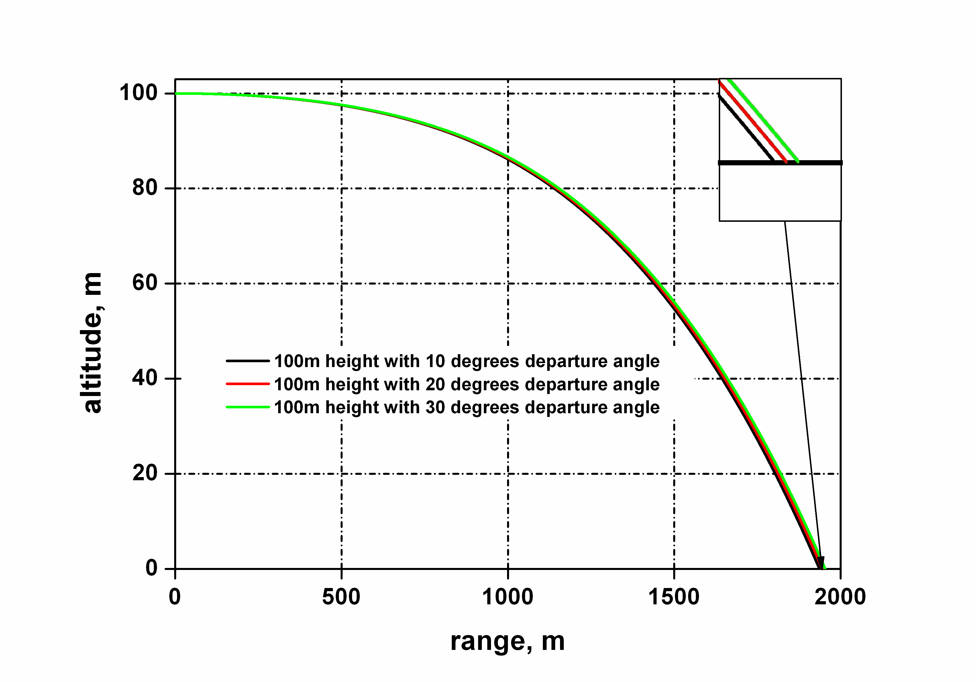
Also the same are depicted in Figure 5 for firing sidewise at 100-m height where the corresponding impact points are 1,997 m, 1,994 m and 1,989 m at the same angles ω relative to helicopter’s flight path direction. The slightly difference in computational target shooting prediction results are illustrated in a better form in the additional zoomed picture in Figure 5.
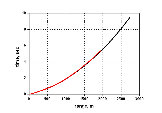
In addition, Figure 6 shows that the total time of flight firing from 300-m height at 30° relative to helicopter’s automatic machine gun velocity is almost 9.5 s. The corresponding value for flat-launching at 100-m height is about 5.3 s. The above results show that the time of projectile flight motion is short, so the applied variable rapid trajectory prediction must be taken into account for high accuracy.
The vertical deflections to target shooting area caused by the aerodynamic jump performance for flat no-wind sidewise are illustrated in Figure 7. The computational results are given for firing angles ω of 10°, 30°, and 50°, respectively, at the first 200 m range.
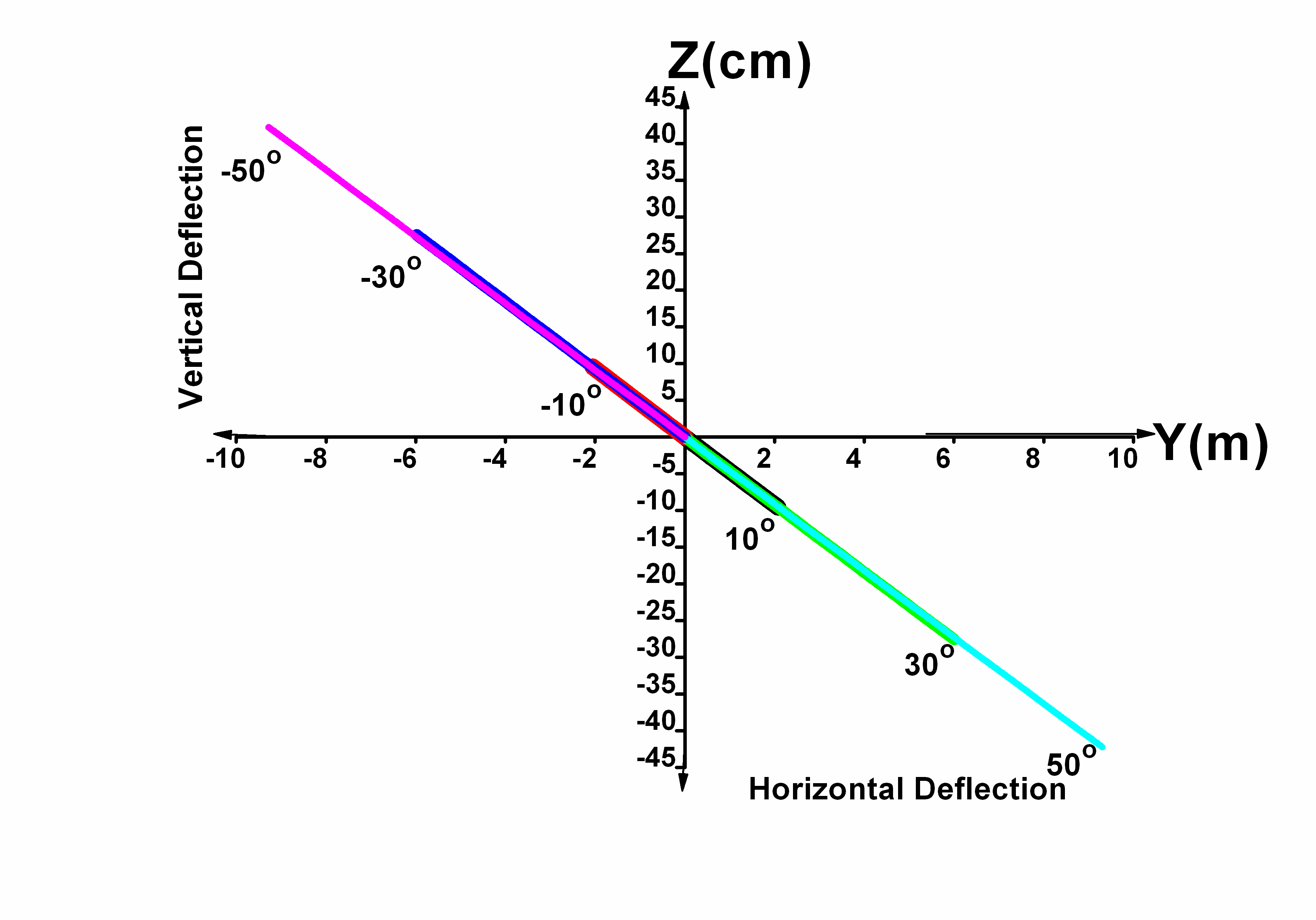
The helicopter altitude was 300 m above mean sea level. For the yaw flight due to initial crossfire of 30-mm XM788 projectile, the lift-force and overturning moment aerodynamic characteristics are obtained from the figures in the Appendix to this paper, depending on the launched Mach number. Vertical deflections Ζ, firing sidewise at positive angles ω, are directed upward according to target’s shooting point (opposite to ZIF-axis direction) in the case of right-hand spin regards to positive rifling twist rate of the helicopter’s automatic gun.
The present analysis computations for the XM788 projectile gives –9.3 cm, –28 cm, and –41 cm vertical deflections corresponding to 2 m, 6 m, and 9 m horizontal deflections for positive firing angles 10°, 30°, and 50°, respectively (Figure 7). For negative values of firing angle ω the projectile strikes the target with vertical deflections of 93 cm, 280 cm and 410 cm, respectively, directed downward in positive ZIF-axis.
Many projectiles show significant nonlinear aerodynamic behaviour, even at relatively small amplitude pitching and yawing motion. In the present analysis this synthesized projectile atmospheric motion is plotted in Figure 8 for the first 200 m of range, The .30-calibre projectile is fired with 805 m/sec at 30° relative to helicopter’s flight speed of 51 m/sec and the combined total muzzle velocity is almost 850 m/s. The produced initial yaw (or sideslip) angle is approximately 1.719°. All significant aerodynamic forces and moments are taken into account according to the figures on the Appendix for the 30-mm XM788 projectile type. The first maximum yaw angle is 2.1° and at the 200-m range has damped to 0.8°, and it is still damping.
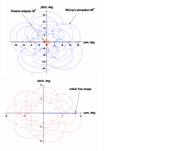
On the other hand, the upper diagram in Figure 8 illustrates the same information from McCoy’s simulation results for the first 200 m of a .50 API M8 bullet trajectory atmospheric motion. It is fired horizontally with 900 m/sec sidewise perpendicular to a high speed aircraft line of flight of 231 m/sec airspeed. The first maximum yaw is approximately 17°, and it occurs about 5 m downrange of the gun muzzle.
Conclusion
The modified linear 6-DOF simulation flight dynamics model is applied for the prediction of spin-stabilized projectiles firing sidewise from low-speed helicopters. Variable aerodynamic force and moment coefficients based on Mach number variations and total angle of attack effects are included for the XM788 projectile trajectory simulations.
A new engineering correlation is proposed for the flat-fire disturbance due to aerodynamic jump performance firing at different angles which relative to the helicopter’s flight path motion. The computational results of the generalized aerodynamic jump formula are verified compared to McCoy’s recognized simulation modelling. Coupled pitching and yawing motion based on the initial crossfire yaw angle is examined for the whole atmospheric motion of the 30-mm XM788 projectile type.
Nomenclature
= aerodynamic jump
= total angle of attack,, deg
CD = drag force aerodynamic coefficient
CLA = lift force aerodynamic coefficient
CLP = roll damping moment aerodynamic coefficient
CMQ = pitch damping moment aerodynamic coefficient
CMA = overturning moment aerodynamic coefficient
CMPA = Magnus moment aerodynamic coefficient
D = projectile reference diameter, m
g = sea-level acceleration gravity, 9.80665 m/s2
IXX = projectile axial moment of inertia, kg∙m2
IYY = projectile transverse moment of inertia about the y-axis through the centre of mass, kg∙m2
ΙΧΧ, ΙΥΥ, ΙΖΖ = diagonal components of the inertia matrix
= complex number ()
= non-dimensional axial moment of inertia
LCGCM = distance from the centre of mass (CG) to the Magnus centre of pressure (CM) along the station line, m
LCGCP = distance from the centre of mass (CG) to the aerodynamic centre of pressure (CP) along the station line, m
l = dimensionless arc length
m = projectile mass, kg
P = non-dimensional axial spin rate,
, = projectile roll, pitch and yaw rates in the moving frame, respectively, rad/s
= projectile velocity components expressed in the no-roll-frame, m/s
V = total aerodynamic velocity, m/s
= projectile’s firing velocity, m/s
= helicopter’s flight speed motion, m/s
= total muzzle velocity, m/s
x, y, z = projectile position coordinates in the inertial frame, m
Z = vertical deflection to target impact point
Greek symbols
α, β = aerodynamic angles of attack and sideslip, deg
φ, θ, ψ = projectile roll, pitch and yaw angles, respectively, deg
= rifling twist rate of the machine gun, calibres/turn
Κ1, Κ2 = dimensional coefficients, πρD3/8m and πρD3/16ΙΥΥ, respectively
ρ = density of air, kg/m3
ω = initial firing angle, deg
Subscripts
o = initial values at the firing site
Appendix
The non-linear variable behaviour depends on Mach number and total angle of attack (yaw angle) variation effects are taken into account for the 30-mm XM788 projectile type,. The most important aerodynamic coefficients are taken into account, according to McCoy’s [9] free-flight data, in the following generalized forms:
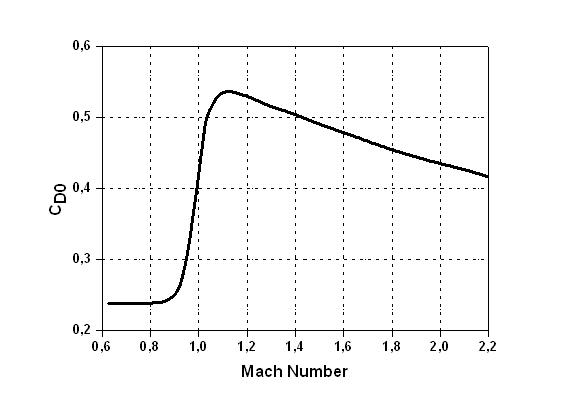
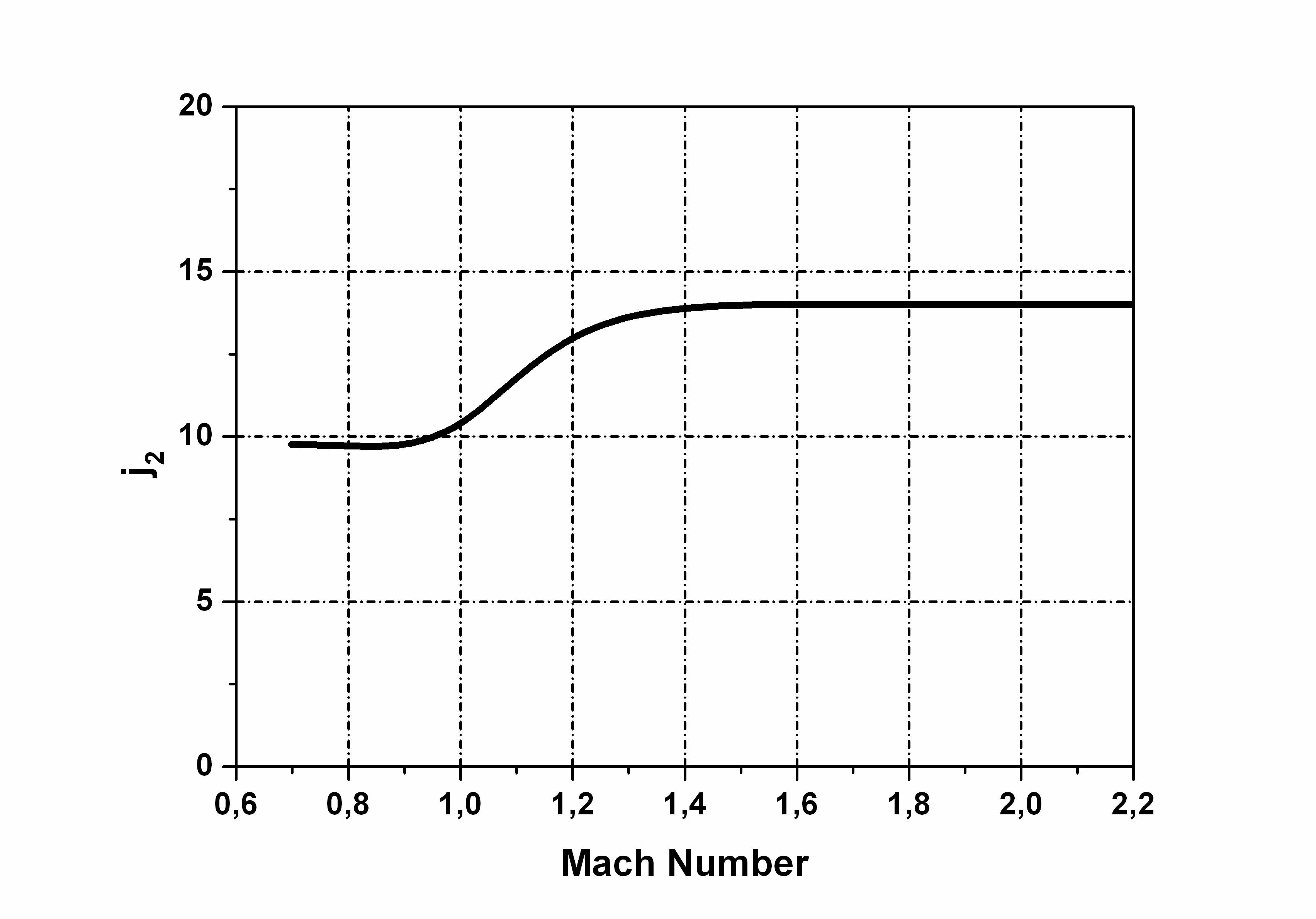
A. Drag coefficient

where:
CDo = zero-yaw drag coefficient
j2 = quadratic yaw-drag coefficient
B. Lift force coefficient
C. Overturning moment coefficient
D. Magnus moment coefficient

CMPAo = zero-yaw Magnus moment coefficient
m2 = cubic Magnus moment coefficient
E. Pitch damping moment coefficient
E. Pitch damping moment coefficient

CMQo = zero-yaw pitch damping moment coefficient
n2 = cubic pitch damping moment coefficient
References
[1] M. Bundy, The Regional Nature of Aerodynamic Jump, Ballistic Research Laboratories Report No.1872, 1999.
[2] T.H. Sterne, On Jump Due to Bore Clearance, Ballistic Research Laboratories Report No.491, 1944.
[3] G. Cooper, Extending the Jump Analysis for Aerodynamic Asymmetry, Army Research Laboratory, ARL-TR-3265, 2004, pp.1-4.
[4] G. Cooper, Projectile Aerodynamic Jump Due to Lateral Impulsives, Army Research Laboratory, ARL-TR-3087, 2003, pp. 1–4.
[5] C.H. Murphy, The Measurement of Non-Linear Forces and Moments by Means of Free Flight Tests, Ballistic Research Laboratories Report No. 974, February 1956. AD 93521.
[6] L. Hainz and M. Costello, “Modified Projectile Linear Theory for Rapid Trajectory Prediction,” Journal of Guidance, Control, and Dynamics, Vol. 28, No. 5, 2005, pp. 1007-1009.
[7] M. Costello and A. Peterson, “Linear Theory of a Dual-Spin Projectile in Atmospheric Flight,” Journal of Guidance, Control, and Dynamics, Vol. 23, No. 5, 2000.
[8] D.N. Gkritzapis, E.E. Panagiotopoulos, D.P. Margaris, and D.G. Papanikas, “Computational Atmospheric Trajectory Simulation Analysis of Spin-Stabilized Projectiles and Small Bullets”, Atmospheric Flight Mechanics Conference and Exhibit, AIAA Paper 2007-6584, 20–23 August 2007, Hilton Head, South Carolina.
[9] R.L. McCoy, Aerodynamic Characteristics of the 30-mm XM788 and XM789 Projectiles, Ballistic Research Laboratories Report No.2432, 1982.
[10] C.H. Murphy, “Circular Pitching and Yawing Motion of Nose Cone Configurations”, Planetary and Space Science, Vol. 4, 1961, pp. 328–336.
[11] M.L. Rasmussen, and D.B. Kirk, On the Pitching and Yawing Motion of a Spinning Symmetric Missile Governed by an Arbitrary Nonlinear Restoring Moment, NASA TN D-2135, 1964.
[12] B. Burchett, A. Peterson, and M. Costello, “Prediction of Swerving Motion of a Dual-Spin Projectile with Lateral Pulse Jets in Atmospheric Flight,” Mathematical and Computer Modelling, Vol. 35, No. 1–2, 2002, pp. 1–14.
[13] R.L. McCoy, Modern Exterior Ballistics, Schiffer, Attlen, PA, 1999.
[14] B. Etkin, Dynamics of Atmospheric Flight, John Wiley and Sons, New York, 1972.
[15] M.J. Amoruso, Euler Angles and Quaternions in Six Degree of Freedom Simulations of Projectiles, Technical Note, 1996.