
Volume 10, Number 1, March 2007
Ballistic Damage In Structurally Loaded Carbon/Epoxy Composite Panels
- 1 Both authors are with Air Vehicles Division, Defence Science and Technology Organisation, 506 Lorimer St. Fishermans Bend, Victoria, 3027, Australia.
Abstract
The effect of structural loading on ballistic damage in carbon/epoxy composites was investigated. Flat panel specimens clamped in a four-point bending rig were shot using 12.7-mm and 20-mm projectiles. The structural loads corresponding to 0, 25%, 50%, and 65% ultimate strength of the specimens were applied. The damage was inspected visually and using ultrasonic C-scan techniques. The specimens were finally loaded to failure to measure their residual stiffness and strength. The test results showed that a low structural load (corresponding to 25% ultimate strength) did not affect the resultant ballistic damage nor the residual stiffness, compared with those of unloaded specimens. Significant increase of damage occurred when higher structural loading was applied. The test results also showed that more damage occurred when ballistic impact was combined with structural loading, than that when they were separately applied. Around 10% residual stiffness reduction was observed for those specimens shot with a structural load close to 65% of ultimate strength. At a structural load close to 65% ultimate strength, around 10% initial stiffness reduction was observed. However, for all cases investigated, structural loading did not significantly affect the residual strength.
Introduction
Owing to their superior structural performance (such as high specific strength, high specific stiffness and high fatigue damage resistance) fibre-reinforced polymer composite materials are increasingly used on aircraft. Some recently developed military helicopters (such as the Eurocopter Tiger and MRH90) have nearly all-composite airframe structures. A large percentage of the composite materials used on aircraft are based on carbon fibre reinforcement.
Due to the nature of their mission, military helicopters are vulnerable to ballistic impact damage from small-arms fire in the battlefield. Knowledge about ballistic damage in the carbon fibre polymer materials is important for military helicopter design, operation, and battle-damage repairs.
Much ballistic testing involving the carbon/epoxy composite materials has been reported [1–4]. In most of the testing work so far reported the test specimens were not under structural loading, despite that the aircraft are generally structurally loaded when experiencing a ballistic impact during the time of conflicts. The only research known to the authors that reported ballistic testing on structurally loaded composite specimens was conducted by the US Air Force [4], in which thin carbon epoxy plates loaded in tension were shot. The results showed that the structural load resulted in up to 20% residual strength reduction to the test specimens. This discovery appears significant, which indicates that the ballistic damage tolerance of aircraft composite structures may be more realistically determined when the structural loading is considered.
This report summarises the work carried out by the Defence Science and Technology Organisation (DSTO) and the Cooperative Research Centre for Advanced Composite Structures Ltd (CRC-ACS) to investigate further the effect of structural loading on ballistic damage in carbon/epoxy composite panel specimens. For the newly developed all-airframe structure helicopters, the composite materials are not only used as thin skins undertaking in-plane loads, but also used to make relatively thick frame structures that also undertake out-of-plane loads. Thus relatively thick specimens and bending loading were considered in this study.
Methods
Test specimens
Flat-plate specimens were made up using 18 plies of uni-directional fabric (98% fibre in warp direction and 2% in weft direction) carbon/epoxy prepreg with a lay-up of [0/45/-45/90/0/90/-45/45/90]s. The prepreg material used was Hexcel M18/G947 [5] with nominal ply thickness of 0.15 mm. The manufacturer recommended curing cycle was followed (180°C for three hours under 400 KPa pressure in an autoclave). The specimen size was 400 mm × 150 mm. A total of 24 specimens were prepared.
Four-point bending rig
The loading rig developed for these experiments is shown in Figure 1. The 4-point bending mechanism is self-explanatory. The load is applied by turning the nuts on the four loading rods evenly to move the front plate towards the rear plate. The rear plate is clamped on a large rigid frame structure. Both the front and rear plates have a square “window” hole, allowing the projectiles to freely shoot through. The support and load spans of the four-point bending rig (Figure 1) are adjustable.
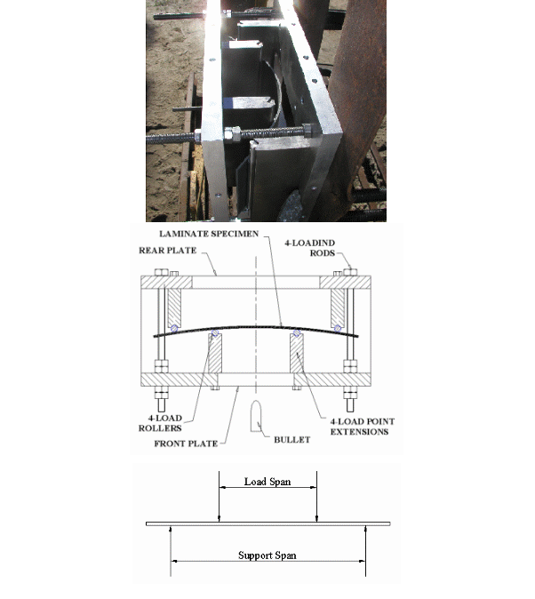
Load calibration tests were conducted using an Instron test machine. The rig with strain-gauged pristine specimens was loaded in compression on the Instron machine (refer to Figure 2a). The calibration tests were used to establish how the distance between the front and rear plate corresponded to the strain on the specimen surface at the centre and the load applied.
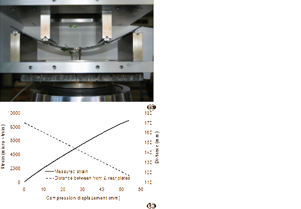
As shown in Figure 2(b), the distance between the front and rear plates clearly defines the strain level with sufficient resolution and thus it was used as a simple and effective way to control the structural loading in the ballistic testing.
Ballistic testing and structural loading
12.7-mm (M2) and 20-mm (TP) ball munitions were fired from rifled guns to the centre of the test specimens installed in the rig. The impact velocities of the projectiles were measured using a chronograph installed in front of the target.
In the ballistic tests the support and load spans used were 360 mm and 180 mm respectively. Four different structural load levels were used:
- unloaded;
- 3,500 µε;
- 7,000 µε; and
- 9,000 µε.
Note that the ultimate failure strain is about 14,000 µε. The above loads were approximately 0, 25%, 50%, and 65%, in terms of strain-based strength criterion, of the ultimate strength respectively.
The test matrix is shown in Table 1.
| Projectile calibre | Load (nominal strain) | |||
|---|---|---|---|---|
| 0 µε | 3,500 µε | 7,000 µε | 9,000 µε | |
| 12.7 mm | 3 tests | 3 tests | 3 tests | 2 tests |
| 20.0 mm | 3 tests | – | 4 tests | 3 tests |
After the ballistic testing, those specimens shot with no structural loadings were structurally loaded to 9,000 µε so that a comparison could be made with those specimens shot with 9,000 µε structural loadings, to see whether more damage would occur when ballistic impact was combined with structural loading (than that when they were separately applied).
Damage assessment
After ballistic tests, the test panels were photographed to record visible damage. The delamination areas around the penetration holes were measured using the ultrasonic C-scan method. The bitmap image files generated from the C-scan were processed using an image processing program called ImageJ [6] to quantify the damage area.
Residual property testing
All the specimens were eventually loaded to failure using the 4-point bending rig installed on the Instron test machine to measure their residual stiffness and strength.
In these tests shorter support and load spans, being 200 mm and 100 mm respectively, were used. With the limited distance between the front and rear plates of the rig, shorter spans were necessary to achieve sufficient strain during residual strength tests (otherwise the deformed specimen would tough the rear plate before the load was fully applied). As no shooting was involved during the residual strength tests, the load span could be shorter.
Figure 3 shows the measured relationship between Instron crosshead displacement and strain gauge readings on a pristine specimen. This relationship was fitted using the following formula:
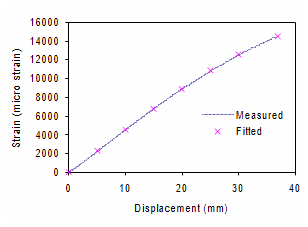

where:
ε = strain at specimen middle surface in micro strain; and
d = Instron crosshead displacement in mm.
Equation (1) was used to convert the Instron displacement to specimen nominal strain for test results processing.
Results and discussion
Ballistic impact velocity
The impact velocities of the projectiles recorded by the chronograph are summarised in Table 2.
Ballistic damage
Visible damage
Figure 4 shows the typical visible damage produced by a 12.7-mm projectile. With reference to this figure, the following can be noted:
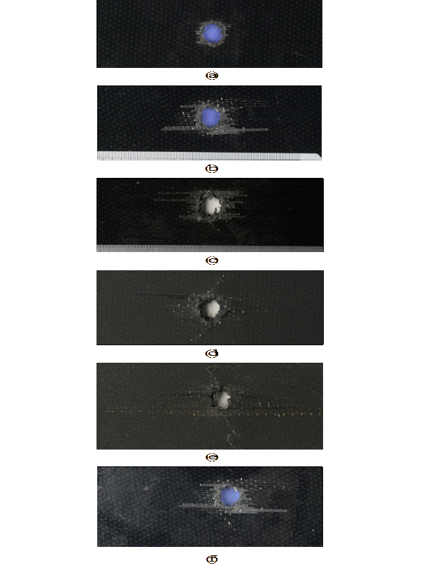
- Visible damage at the projectile exit side was more significant than that at the entrance side (Figures 4(a) and 4(b)). (Note that the real visible damage in Figure 4(b) should be considered to be less pronounced than what is shown since the damage at the area far away from the hole edge was insignificant where only a little surface fibres were peeled).
- Compared with that of structurally unloaded specimen, increase of the visible damage on the specimen shot with 3,500 µε structural loading did not appear significant (Figures 4(b) and 4(c)).
- Significant increase of visible damage occurred as the structural loading further increased (Figures 4(d) and 4(e)). When shot with higher structural loadings, deep cracks developed on the specimens spreading from the hole edges. These cracks were along both the span-wise direction and its perpendicular direction.
- Significantly more visible damage occurred when ballistic impact was combined with structural loading, than that when they were separately applied (Figures 4(e) and 4(f)).
Figure 5 shows the typical visible damage produced by a 20-mm projectile. Similar to those described above, the following can also be seen from this figure:
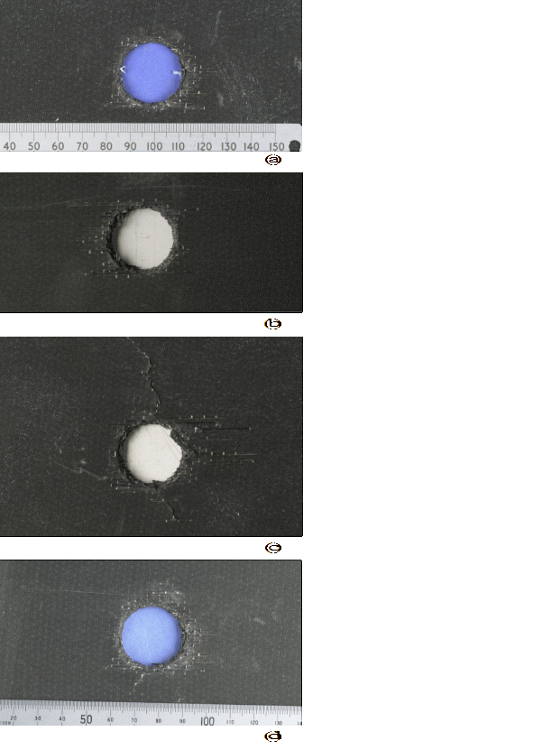
- Significantly larger visible damage in the form of deep cracks occurred when shot under the high structural loading (Figure 5(c));
- Visible damage was significantly larger when ballistic impact was combined with the structural loading, than that when they were separately applied (Figures 5(c) and 5(d)).
Unlike that in the 12.7-mm projectile case, the visible damage on the specimen shot with a 20-mm projectile under 7,000 µε was still not significantly larger than that on the specimen shot without structural loading (Figures 5(a) and 5(b)).
Total damage area
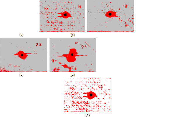
Typical C-scan images of specimens with ballistic damage caused by 12.7-mm and 20-mm projectiles are shown in Figures 6 and 7, respectively. These images have been processed, where the black area and its adjacent grey (red in the colour diagram) area are considered to be the total damaged area (covering all the area with delamination and cracks). The total damage areas quantified using the ImageJ software for all the specimens tested are summarised in Tables 3 and 4.

| Projectile calibre | Measured impact speed (m/s) | ||
|---|---|---|---|
| Lowest | Highest | Average | |
| 12.7 mm | 856 | 894 | 883 |
| 20.0 mm | 1,084 | 1,100 | 1,093 |
Similar to the trends with the visible damage discussed in the previous section, the following trends with the total damage can be observed in Figures 6 and 7, and in Tables 3 and 4:
- Compared with that of structurally unloaded specimen, no increase of the total damage area on the specimen shot with 3,500 µε structural loading was observed (Figures 6(a) and 6(b) and Table 3).
- Clear increase of total damage area occurred when the structural loading increased to 7,000 µε (Figures 6(c), Figure 7(b) and Tables 3 and 4). Significant increase of total damage area occurred when the structural loading further increased to 9,000 µε (Figures 6(d), Figure 7(c) and Tables 3 and 4).
- Total damage was significantly larger when ballistic impact was combined with structural loading, than that when they were separately applied (Figures 6(d) and 6(e), Figures 7(c) and 7(d), and Tables 3 and 4).
Residual stiffness and strength
Figure 8 plots the measured strain-compression load curve with a pristine specimen. As shown in Figure 8 the curve becomes clearly non-linear when strain is over 8,000 µε. Several audible cracking sounds occurred when the strain was above 11,000 µε until the final catastrophic failure. These clearly suggested that the failure was in a progressive manner.
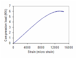
Figure 9 shows the failure pattern of a specimen damaged with a 20-mm projectile shot. The failure patterns for all the specimens are similar, being lamina break and large area/multiple layer delamination at the middle of the specimens.
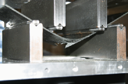
Figure 10 plots the strain-compression load curves measured in all the tests with ballistically damaged specimens. When the strain was over 10,000 µε, large audible cracking and visible lamina break/delamination cracks occurred. The load dropped with onset of this audible cracking, and then raised again until the final failure.
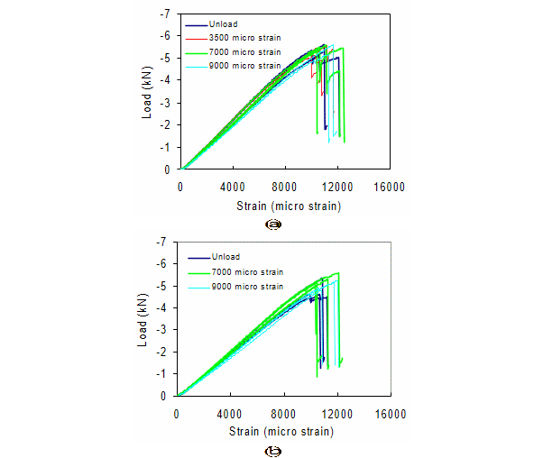
Tables 5 and 6 summarise the maximum compression load measured in each test. Initial stiffness of all the curves in Figure 10 was also calculated and listed in these tables. The initial stiffness was calculated using the strain and load data between 1,000 µε and 3,000 µε.
From Tables 5 and 6 and Figures 9 and 10, one can see that:
- 9,000 µε structural loading resulted in 11.9% and 7.3% initial stiffness reduction for specimens with 12.7-mm and 20-mm projectile damage, compared with the unloaded specimens;
- projectile damage at 3,500 µε and 7,000 µε structural loadings did not have a clear influence on the initial stiffness; and
- structural loading during impact did not significantly affect the residual strength.
| Test No | Total damage area (mm2) | ||||
|---|---|---|---|---|---|
| Shot with 0~9000 µε loading (µε) | Loading after shot (µε) | ||||
| 0 | 3,500 | 7,000 | 9,000 | 9,000 | |
| 1 | 1,091 | 1,088 | 1,170 | 2,049 | 1,201 |
| 2 | 1,031 | 925 | 1,142 | 2,348 | 1,104 |
| 3 | 848 | 886 | 1,215 | – | 1,018 |
| Average | 990 | 967 | 1,175 | 2,198 | 1,108 |
| Ratio of average | 100% | 98% | 119% | 222% | 112% |
| Test No | Total damage area (mm2) | ||||
|---|---|---|---|---|---|
| Shot with 0~9,000 µε loading(µε) | Loading after shot (µε) | ||||
| 0 | 3,500 | 7,000 | 9,000 | 9,000 | |
| 1 | 1,600 | – | 1,623 | 3,011 | 1,771 |
| 2 | 1,440 | – | 1,634 | 2,373 | 1,741 |
| 3 | 1,409 | – | 1,523 | 2,592 | 1,771 |
| 4 | - | – | 1,660 | – | – |
| Average | 1,483 | – | 1,610 | 2,659 | 1,761 |
| Ratio of average | 100% | – | 109% | 179% | 119% |
Note that although the higher structural loading resulted in larger damage area as indicated in the previous section, it did not result in lower residual strength, contradictory to what was anticipated.
The reason can be attributed to the nature of progressive failure of the specimen under the four-point bending condition. The delamination area/cracks were spreading while the loading was continued. The maximum load apparently corresponded to the final state of damage in the specimen but not the initial damage state of the specimen.
Note that progressive failure even occurred in tensile testing of notched laminate specimens [7]. In bending testing, this is much more pronounced, with the ultimate strain much higher than the initial failure stain.
Conclusions
In this work, the effect of structural loading on ballistic damage in carbon/epoxy composites was investigated. Flat-panel specimens clamped in a 4-point bending rig were shot using 12.7-mm and 20-mm projectiles. The structural loads applied corresponded to 0, 25%, 50%, and 65% ultimate strength of the specimens. The damage was inspected visually and using the ultrasonic C-scan technique. The specimens were finally loaded to failure to measure their residual stiffness and strength. The following major conclusions may be drawn from the test results:
- Lower structural loading did not affect the resultant ballistic damage size nor the residual stiffness, compared with those of unloaded specimens.
- Significant increase of damage (both visible and delamination) occurred when higher structural loading was applied prior to impact. The test results also showed that more damage occurred when ballistic impact was combined with structural loading, than that when they were separately applied.
- With the highest structural load applied in this study, around 10% initial stiffness reduction was observed following ballistic impact. However, structural loading did not significantly affect the residual strength, probably owing to the progressive failure manner of the test specimens under the four-point bending condition.
Acknowledgments
The authors would like to thank their colleagues Dr S. Cimpoeru, Mr S. Pattie, Mr F. Gritto, Mr H. Morton, Mr R. Gray, Mr I. Stoyanovski, Mr R. Bartholomeusz, and Mr. Vodicka at DSTO for their valuable contributions in ballistic testing, C-scan inspection, specimen manufacture, residual property testing, and initial task management; as well as Scientific Engineering Services, DSTO and Boeing DSTO Operations for manufacture and modification of the ballistic test rig.
This work contributed to work programs that were funded and supported by the Cooperative Research Centre for Advanced Composite Structures (CRC-ACS) and the Defence Science and Technology Organisation (DSTO).
| Initial stiffness (kN/103µε) | Maximum load (kN) | |||||||
|---|---|---|---|---|---|---|---|---|
| Test No | Unload | 3,500 µε | 7,000 µε | 9,000 µε | Unload | 3,500 µε | 7,000 µε | 9,000 µε |
| 1 | 0.582 | 0.589 | 0.582 | 0.511 | 5.62 | 5.27 | 5.39 | 5.52 |
| 2 | 0.591 | 0.545 | 0.543 | 0.498 | 5.37 | 5.13 | 5.50 | 5.18 |
| 3 | 0.543 | 0.582 | 0.535 | - | 5.12 | 5.56 | 5.58 | – |
| Average | 0.572 | 0.572 | 0.553 | 0.504 | 5.37 | 5.32 | 5.49 | 5.35 |
| Ratio of average | 100% | 100% | 96.7% | 88.1% | 100% | 99.1% | 102.2% | 99.6% |
| Initial stiffness (kN/103µε) | Maximum load (kN) | |||||
|---|---|---|---|---|---|---|
| Test No | Unload | 7,000 µε | 9,000 µε | Unload | 7,000 µε | 9,000 µε |
| 1 | 0.489 | 0.530 | 0.467 | 4.48 | 5.62 | 5.15 |
| 2 | 0.506 | 0.526 | 0.472 | 4.62 | 5.15 | 5.25 |
| 3 | 0.539 | 0.502 | 0.483 | 5.35 | 5.01 | 4.80 |
| 4 | – | 0.467 | – | – | 5.32 | – |
| Average | 0.511 | 0.506 | 0.474 | 4.82 | 5.28 | 5.07 |
| Ratio of average | 100% | 99.0% | 92.7% | 100.0% | 109.5% | 105.2% |
References
[1] A. Resnyansky, The Impact Response of Composite Materials Involved in the Helicopter Vulnerability Assessment (Literature Review), DSTO technical report, DSTO-TR-1842, April 2006.
[2] N. Chandra and Rajendran, “Micromechanics Based Modelling of Damage in Composites Under High Velocity Impact—A Review”, International Conference on Structures Under Shock and Impact, SUSI, pp. 421–432, 1998.
[3] J. Wang and R. Bartholomeusz, “Ballistic Damage in Carbon/Epoxy Composite Panels”, Journal of Battlefield Technology, Vol. 7, No. 1. 2004, pp. 7–13.
[4] M. Jacobson, “Addendum to Design Manual for Impact Damage Tolerant Aircraft Structure”, AGARD-AG-238. 1998. Northrop Corporation Aircraft Division, Hawthorne, CA90250, USA.
[5] HexPly® M18/1 180°C Curing Epoxy Matrix, Product Datasheet, Hexcel, June 2005.
[6] W. Rasband, ImageJ image processing program, http:www.jasc.com.
[7] J. Wang, P. Callus, and M. Bannister, “Experimental and Numerical Investigation of the Tension and Compression Strength of Un-Notched and Notched Quasi-Isotropic Laminates”, Journal of Composite Structures, 64, 2004, pp. 297–306.