
Volume 9, Number 3, November 2006
Testing And Development Methods For Laser Decoys
- 1 DRDC Valcartier, 2459 Pie-XI Blvd North, Val-Bélair, Québec Canada, G3J 1X5.
Abstract
As laser and laser-guided weapons are becoming less expensive and more available around the world, methods to defeat this class of threat need to be investigated to improve the protection of military platforms and assets. A laser decoy is an attractive choice as it can be deployed in a timely manner and accurately. Additionally, there is a potential to integrate this technology with a minimum of hardware changes. Even if the technique is quite simple, a variety of parameters needs to be optimized to decoy successfully an incoming laser-guided weapon. Although this paper does not provide the recipe to develop an effective laser decoy system, it introduces an escalating method to test the effectiveness of laser decoys. Four levels of testing are introduced with a discussion showing the strengths and limitations related to each of these levels. The test levels vary in complexity of set-up and degree of realism associated with them. Finally, this paper discusses briefly the development and test methods used by Defence R&D Canada Valcartier (DRDC Valcartier) in the development of laser decoys.
Introduction
Battlefield laser technology is now mature and is becoming increasingly less expensive. As such, laser-guided weapon are becoming attractive to a lot of combat-capable forces, whether traditional or terrorist-based. These weapons use a combination of a laser designator to mark a target and a laser seeker installed on the front of a missile to define a guidance corridor and ensure a high hit probability. Nowadays, the technologies required to build such systems can easily be found commercially off-the-shelf. Since this technology is mature and available, combat forces require an effective way of defeating it.
The principle of laser decoying has been known for a long time, however only recently has it become easy to implement on small assets such as ground vehicles. The same commercial and technological advances that make the laser guidance inexpensive and reliable also make the laser decoy more affordable and less technologically demanding.
Semi-active laser guidance and laser decoy principles
The principle of laser guidance is relatively straightforward and effective. To guide a weapon onto a target accurately, a laser designator beams energy onto a target. At the same time, a weapon is launched/released with a laser seeker in the front end and a means of control. The laser seeker detects the reflected energy and the weapon homes on the signal. The laser designator can be located either on the launching platform or at any other location that reveals a direct line of sight to the target.
Similarly, the laser decoy technique is simple. Once a designation signal is detected, the threatened platform responds and designates another target (such as the ground, an obscurant, or vegetation) to emulate the initial designation signal and to present an alternative target to the laser seeker. A typical laser decoy system is composed of the following:
- Laser warning receiver (LWR). The first step in the laser decoy technique is to detect the presence of the laser designation. Ideally, the LWR should cover all possible designation aspect angles and is sensitive enough to detect the designation signal in less-than-ideal weather conditions.
- Laser code predictor or laser controller. A laser designator can use pulse repetition frequency, pulse codes, or other means to mark a target. A code predictor is required to decipher the incoming signal and must be able to predict what the signal is going to be. At the very least, a laser controller is used to activate the decoy if prediction of the laser code is not required.
- Laser or optical power source at the proper wavelength. Laser seekers are designed to look at optical signals that are within a specific waveband, of given magnitude, and with expected signal characteristics.
Figure 1 illustrates a typical engagement where a laser-designated weapon is launched and where a laser decoy is also activated.

- The engagement starts with a laser-guided weapon launched or released towards the target (in this case the light armoured vehicle (LAV)).
- It follows with the designation (or marking) of the target with properly encoded or modulated optical energy. In this case the laser designator marks the LAV from the left.
- The guided weapon detects the reflected laser energy, which enables the homing process. (See Figure 1a).
- In parallel, a LWR located on the LAV detects the laser energy and feeds the code predictor with the incoming signal. The code predictor analyses the modulation or the encoding and generates an electrical signal that activates an onboard countermeasure laser.
- The onboard laser (on the LAV) emits a decoy on the ground emulating an alternative target for the semi-active laser-guided weapon in flight.
- Finally the guided weapon detects the alternative target and homes toward it. (See Figure 1b).
Even though the principle of the laser decoy is simple, a number of parameters must be optimized to ensure that the guided weapon will detect and switch over to the alternative target. The effectiveness of laser decoys depends on a careful optimization of these parameters.
| (a) Weapon is launched, target designation is detected by the weapon and it homes on the target. |
|---|
| (b) Designation is detected by LWR, decoy is emitted and weapon homes on new target. |
Methodical development and testing
Since many parameters (that can be interrelated) need to be optimized in the development of an operational laser decoy, DRDC Valcartier proposes a gradual approach. The testing can be characterized into four levels:
- Level I—Virtual modelling and simulation. The system is modelled mathematically and simulated into a synthetic environment using off-the shelf PC and simulation software. At this level, each parameter can be tuned without any physical limitations.
- Level II—Open and closed hardware-in-the-loop (HIL) simulation. Using the mathematical models developed at Level I, a simulation is built where specific hardware is introduced. Limitations of the hardware such as bandwidth and maximum sampling rate of the input and the output of the PC cards add to the complexity of the testing.
- Level III—Static and dynamic field tests. At this level, a realistic laser designator, a radiometer with guidance, and tracking electronics and sensors for the laser decoy system under development are integrated and tested in the field.
- Level IV—Weapon in flight test. This level of testing is the most realistic and can often provide a proof of effectiveness to customers. A semi-active laser-guided weapon is launched toward the system and the effectiveness of the countermeasure is assessed.
Each level of testing is designed to provide the necessary information to understand the effects and feed the next level of testing. A similar approach has been utilized by the US Active Defense System Program [1].
Additionally, this approach is compatible with the Canadian Forces proposed strategy for concept development and experimentation:
“In assessing platform and weapon performance, there are limits to what can be safely achieved. M&S can supplement testing in such instances by providing information not available from real tests. Where such intractability occurs in obtaining data from real tests, complex parametric studies may be conducted of different test configurations quickly and in a relatively inexpensive manner. From such results, inexpensive technology demonstrators may be built to further refine test requirements before any real tests are done.”[2]
One could probably design and develop a system using only Level IV. However this task would be very complex, time consuming, and expensive without guaranty of success.
Level i—virtual modelling and simulation
The first step to develop a laser decoy system is to understand the scenario(s) and the environment that the system will be used in. The Canadian Forces are moving to a simulation-based acquisition to help define capability requirements:
“In both the mid and near term axes, simulation-based acquisition (SBA) should prove to be a valuable tool in transforming concepts into capabilities. Representations of proposed capabilities can be constructed and tested in simulated environments. These virtual prototypes can be used to refine system requirements and relate tradeoffs and engineering decisions to these requirements. Subsequently, computer-based representations can be maintained as development and production occur, and as modifications are introduced throughout the life cycle. The results can be more affordable systems that are better attuned to an operator's needs, easier to assimilate, and easier to modify.”[3]
Similarly we propose that mathematical modelling of the threat, the environment (such as atmospheric, surface, and reflectivity), and the countermeasure system is a crucial step in defining the requirements.
Missing or incomplete information about specific laser seekers or signal processing algorithms can often be replaced with generic signal processing algorithms and simple encoding or modulation techniques. Phase-lock loop, digital filtering, and gate processing are examples of signal processing that could be used when associated with generic encoding and modulation. This step will inevitably provide valuable information on how a seeker might home on the target.
The interactive mathematical models required in the simulation are listed below.
- Threat laser seeker. As discussed above, a laser seeker with its signal processing is required. Adding multiple signal processing methods will enable the simulation of different threat types and different decoy techniques. The seeker model should also incorporate optical details such as Field Of View (FOV), sensitivity, spatial resolution of targets, and optical bandwidth. The accuracy of the seeker algorithm will define the resolution of the laser decoy parameters.
- Guided-weapon airframe and propulsion. Aerodynamics, guidance laws, and control algorithms are needed to simulate the fly-out of the weapon.
- Laser target designator. The target marking system must be modelled to stimulate the laser seeker model. The model modulation technique and model fidelity used must match the ones chosen for the laser seeker.
- Atmospheric models. The laser energy propagation calculations and the weapon fly-out model require an atmosphere environment to run properly.
- Reflectivity and/or light surface interaction. The interaction of the laser energy on surfaces such as ground or targets must be modelled adequately to represent the physics needed by the laser seeker to home onto the reflected signal.
- Laser decoy system. The laser decoy system that is composed of (as a minimum) a LWR, a processor (code prediction), and a laser must be included. Similarly, the models of the LWR, code predictor, and laser must match the laser seeker and the laser designator already described.
The fully virtual synthetic environments created with the mathematical models above are very valuable in the analysis of the laser decoy parameters. The main advantages are as following:
- All parameters are fully tuneable. Each threat and laser decoy system parameter can be modified and tested rapidly to assess the effect.
- The cost of each run is essentially zero once the model is completed.
- Modifications to add new types of threat or new predictor algorithms are quick and inexpensive.
- All parameters of the simulation/engagement can be fully analysed. In a virtual simulation a large number of test points can be monitored.
- Prototypes of laser decoy system control software can be used or emulated in order to test the effectiveness of the design. The laser code predictor and LWR embedded software can be tested and modified rapidly even if the hardware is not available or even designed.
There are also limitations and disadvantages related to the use of purely virtual simulation.
- Verification, validation, and certification are complex and costly steps that can often only be partially done considering the information available.
- Some of the physics cannot be fully modelled and will introduce errors. Experts must be involved to model acceptably different physical and mathematical aspect of the simulation.
- The accuracy of a simulation is directly related to the processing power. This may cause a simulation run to take a long time to be computed if very high accuracy is required and small simulation step sizes are used.
- The emulated control software will not be running on the same architecture and therefore it will not be submitted to real-time and hardware limitations. Software designs may be very efficient within a simulation but found unachievable in realistic hardware or require too expensive architecture.
Once some of the complexity and the requirements for the laser decoy are understood using virtual simulation, the laser decoy hardware can be designed, built and/or introduced in to the simulation.
Level ii—open and closed hardware in the loop simulation
The purpose of introducing hardware in a simulation is to remove or verify some assumptions made during the modelling (Level I) phase [4]. With the modelling phase completed or well advanced, a laser decoy developer must start its design and possibly start prototyping hardware.
In order to test the interactivity and the performance of hardware linked to a simulation, it must be run in real time and with a simulation step size small enough to capture all required events [5]. This real-time requirement is important even if the hardware linked to the simulation does not require synchronization. Running in real time provides a common time frame between the simulation and any externally linked hardware.
Below are examples of modules that can be implemented in hardware to replace part of a simulation.
- Laser decoy system processor: LWR, laser code predictor, and system control hardware may contain digital and/or analogue signal processors and embedded software. Once the hardware and software of the mentioned items have been chosen or designed, they can be linked to the simulation. The simulation platform must provide the analogue and digital interfaces to mate with the external components. These generally include inputs from sensors such as LWR detectors, other control signals present in the system, and outputs produced by the external processors.
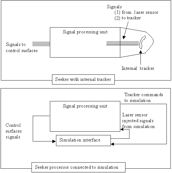
- Laser seeker processor: a threat, surrogate, or generic laser seeker processor not including the laser sensor. A typical laser seeker can be schematised into a position sensitive sensor and a signal processing unit. The processing unit analyses the signals coming from the position sensor to determine the target relative azimuth an elevation and if the laser code/modulation received coincide with the pre-programmed data. If this processor is linked to the simulation, the simulator must provide a capability to inject the signals that are normally provided by the laser position sensor (See Figure 2).
- Two types of target tracking are often used in homing or semi-active homing weapons. Depending on the type of tracking used, the introduction of a laser seeker processor will differ.
- Using an independent internal target tracker. In this configuration, the tracker is not mechanically linked to the body of the weapon and orients itself so the internal sensor is aligned with the target. This method is normally used with proportional navigation. With this method, the seeker processor provides commands to the tracker system for alignment with the target. The weapon control surface commands can also be provided by this module or by another guidance processor.
- Using the airflow around the weapon to align the seeker to the velocity vector of the weapon. This is normally used in pure pursuit guidance. In this case the laser seeker processor will provide commands to the control surfaces of the weapon to align the velocity vector on a direct line of sight (LOS) to the target.
- Depending on the configuration chosen, the processor that is linked to the simulation will provide tracker commands or control surfaces commands to close the loop. The simulation calculates new weapon positions and sends the laser sensor signal to the seeker processors (see Figure2).
- Figure 3 illustrates a closed-loop simulation set-up where a laser seeker processor, a LWR processor and a laser code predictor processor are integrated. In this set-up, the LWR is linked to the laser code predictor directly to provide the laser designation modulation/coding information without going through the simulation computer. Alternatively the LWR and the laser code predictor processor could be linked via the simulation computer where the signal could be manipulated or tuned to test different solutions.
- A higher level of hardware integration is possible although this level is not often completed in closed-loop form due to the complexity and the cost of such set-up.

- For example, realistic laser sensors added to a designation laser or designation laser emulation light source could be integrated to form a complete system. However, a closed-loop simulation with this hardware would be complex and expensive; it would require a large laboratory and additional optical equipment to modify the laser and light source optical characteristics to represent the dynamics of the simulation. For example one might need a motorized 3 or 6 degrees of freedom platform for each sensor and light sources with a specialised variable attenuator to simulate the dynamically varying power and relative angular movement of each parts.
- Most often the sensors and laser(s) are added in open-loop simulation were they are used to test the capability of the sensors or laser to be used in the prototype or final design. An example of such a set up could be to use a laser source, with tuneable optical power characteristics to test the sensitivity of a LWR and LWR laser sensor.
The developer of a laser decoy system may use the open-loop simulation to test its hardware and populate the model developed at Level I with the resultant characteristics. Once that is completed, the results can be integrated into the simulation depicted in Figure 3 to test the system algorithms and hardware implementation.
The use of the actual hardware in a simulation removes assumptions and limitations associated with the modelled items that could have been overseen in the virtual environment. Additionally, using a realistic laser seeker processor improves the degree of confidence that the decoy techniques are effective. It is easy to emulate the behaviour of a laser seeker in a virtual simulation; however the presence of real hardware increases the reliability of the results. As for the laser sensors, open-loop hardware simulation is the best method to obtain the operational characteristics in a laboratory environment.
Although these advantages are attractive, one may not overlook the difficulties associated with properly integrating the hardware in to a real-time closed-loop simulation.
- Each hardware module may require customized and specialized electronic interfaces. For example there might not be any commercial off-the-shelf PC boards capable of dynamically (in real-time) emulating the electrical signals representing the outputs of a LWR or seeker sensor. The development of such specialized electronics might be costly and time consuming.
- The complexity associated with real-time simulation as compared to a non-real-time simulation can be orders of magnitude, especially if events in the simulation happen very fast [5]. This is the case for laser decoy simulation where the designation laser signal is pulse modulated or coded.
- As mentioned already, it is very difficult and expensive to include laser sources and sensors into a closed-loop simulation.
- Even with all the processors integrated into the simulation, with or without sensor and laser source, some of the physics and dynamics of the engagement cannot be simulated easily. The physical characteristics of the terrain surfaces (decoy reflection) and the dynamic range of the injected laser sensor signal are examples.
- In order to further increase the level of realism and to operate the system under more operational conditions, testing in the field is required.
Level iii—static and dynamic field tests
Having analyzed the scenarios and the prototype hardware in the laboratory, the system is now ready to be integrated together (if not already done so in the laboratory) and tested with realistic laser sources under operational conditions in the field. At this level, the system requires pass or fail criteria and test equipment to study the effectiveness of the countermeasure.
Two types of scenarios are possible, namely: static tests and dynamic tests. The difference between static and dynamic test comes from the target (where the laser decoy is installed). In a dynamic scenario, the target is free to move and use manoeuvre as an additional countermeasure. For both types, the laser decoy system is positioned at a significant range away from a laser designator. As part of the decoy system, a LWR is installed looking at the designator. The laser that will emit the false target can be positioned at a fixed location on the threat platform and use an optical system capable of directing the laser beam to a different location on the ground or onto a reflecting surface.
The next step in testing the effectiveness of the system requires a mean of measuring the effect of the additional laser energy on a laser seeker. This can be done by co-aligning a video camera with a radiometer and tracking system (equivalent to a laser seeker) on a motorized pan and tilt platform. The result can be displayed to an operator in two different ways, depending which kind of laser seeker is being emulated.
With an emulation of a laser seeker that does not use an internal tracker, the motorized platform can be controlled by the commands sent to the control surfaces of the weapon (from the laser seeker processor). An operator can then assess the effectiveness of a countermeasure by looking at the image provided by the video camera. The countermeasure is effective if the camera, co-aligned with the seeker, is moving away from the target towards the laser decoy spot position when the decoy is activated.
With an emulation of a laser seeker that integrates an internal tracker, the task is more complex. The motorized pan and tilt platform cannot be controlled by the commands sent to the control surfaces because they direct the weapon on a collision path via proportional navigation and might not align the pan and tilt towards the target. Proportional navigation uses the velocity of the weapon to calculate the control surfaces commands. In our case the weapon is not moving. This would cause errors in the control surface commands. To solve that problem, an overlay (cross-hair) of where the tracker is looking (centre FOV) can be displayed over the images. The overlay position can be calculated with the tracker command signals found for the HIL simulation (see Figure 2). With the camera centred on the target, an operator only needs to monitor where the tracker is looking to determine if a countermeasure is effective.
Dynamics testing adds to the complexity. The laser decoy countermeasure is positioned on a moving ground vehicle. The laser designator operator tracks the target as in an operational scenario. With an emulation of a laser seeker that uses an internal tracker, the platform—where the seeker and camera are installed—needs to track and point to the target in order to provide a reference point where the laser designation is. With an emulation of a laser seeker that does not use an internal tracker, the motorized pan and tilt platform needs a means to point at the target prior to the designation being activated in order to ensure that the laser seeker is pointing in the right direction once the engagement begins. For the remainder of the engagement, the platform follows the most attractive laser target.
One solution to solve the initial alignment problem is to use GPS receivers on the moving target and the motorized platform. It is then possible to compute the angular relations between the target and the pan and tilt table. Adding a GPS position sensor also provides an easy solution to distinguish between targets if multiple vehicles are in the testing area. If more than one laser decoy system requires testing and limited use of a testing area is possible, a GPS receiver with a different ID code can be installed on each target. Sequential engagement with multiple targets will then be possible.
Static and dynamic field tests are useful to determine if a laser decoy technique is effective. With the proposed method, the results are in video format and easily interpretable by the user. The fact that the prototype or operational laser decoy system hardware is used provides valuable data on the system readiness and operability. The field environment and weather conditions, if chosen appropriately, can be similar to operational conditions that may affect the operability and effectiveness of the hardware. Laser energy propagations and reflections cannot easily be modelled in the previous simulation steps.
Even with these advantages, field tests are complex and more expensive to conduct than simulations. Modifying a laser decoy prototype rapidly to try a different laser decoy techniques might not be possible. In the field tests proposed, one major deficiency can be identified. The range between the seeker (emulator) and the target does not vary as it would in a real weapon flying condition.
Level iv—weapon in flight test
Only one method can fully test the effectiveness of a laser decoy system, and that is the launching of a semi-active laser weapon at a target protected by such a system. This very realistic test ensures that all the interactions and dynamics of an operational engagement are respected. Of course, expensive and difficult to replace equipment might require protection against an unexpected hit.
Totally eliminating the risk of damage to the laser decoy equipment during a live fire test is probably impossible. One might move part or the complete decoy system to a safer distance from the target to reduce the risk. To achieve this, there are two solutions:
- The system can be positioned at a safe location, with a direct LOS to the target while the LWR sensors are kept on or near the target. The LWR sensors remains at risk and the rest of the equipment can even be protected by a bunker with an opening to let the laser decoy energy out. Some modifications will be required to the system. The increased distance and modified location of the LWR sensors needs to be accounted for in the LWR threat declaration and laser code prediction algorithms. Secondly, the decoy laser source is not located on or near the target and might require some optical manipulation to produce the same decoy spot pattern. The divergence and beam shape have to account for the new position that will introduce different angular relations.
- Another solution is to position the whole system at the remote and safe position with direct LOS to the target. Some modifications to the LWR sensors would be required. Since the LWR sensor normally uses the direct laser energy to detect and declare a laser threat. One may need to completely modify the LWR sensor and use a different radiometer to detect the designation laser energy. Again, the distance and different angular relations involved between the target and the LWR system is to be accounted for in the signal processing.
Weapon in-flight tests are great demonstrations of effectiveness to customers, and limit if not eliminate the simulated interaction and dynamics of the test. However they are very expensive and might be risky for the prototype equipment.
These optimal effectiveness tests are essential prior to fielding a laser decoy system, no matter how much laboratory and static testing (Level I to III) was done. Weapon in flight test are the most reliable to mimic operational conditions for the system. However, as it is a system test, analysis of any failures and successes of the countermeasure might be very limited. It might be impossible to pin-point causes of failure since it is impossible to monitor and record all internal signals and the status of the systems during the test.
Process being used by DRDC valcartier
DRDC is developing a prototype of integrated Defensive Aids Suite (DAS) for LAVs [6,7]. One of the countermeasures being developed in the integrated DAS is the laser decoy. Canada has chosen to use all levels of tests discussed in the current paper to develop the decoy system.
DRDC has produced a personal computer (PC)-based virtual simulation called LaserCM where a laser seeker based on a four-quadrant detector is modelled with generic signal processing algorithms. These algorithms can emulate different target detection and lock-on mechanisms. Additionally, laser designation, LWR, and seeker optical characteristics can be modified to match a variety of possible systems.
The LaserCM model development and validation based on test results from Level II and III tests provide specific requirements for the continuing development of the laser code predictor and control of the laser system.
A generic laser seeker processor has been integrated into the virtual model. The processor custom interface to the virtual model provides the target designation and laser decoy electrical signals that would normally be produced by a laser seeker sensor. The simulation can run in real-time in a closed loop configuration. This set-up is called the Laser Decoy Hardware-In-the-Loop (LaDHIL) simulator. The use of the LaDHIL simulator enables the study of different laser decoy techniques that would normally be very expensive to study using only hardware. For example, the seeker processor simulation interface can be used to test different laser decoy modulation or code characteristics that would require different hardware laser systems. The reuse of the LaserCM model in the LaDHIL simulator reduced the cost and the time required for the development. At the same time, the simulation results obtained from LaDHIL can be used to validate the laser seeker processor model of the LaserCM simulation.
The LWR (used in the laser decoy prototype) and laser code predictor were not integrated to the LaDHIL simulator since they were already developed and tested in both the laboratory and the field. They were successfully tested at more than one occasion on various laser designators prior to the start of the development for the laser decoy [8].
DRDC has developed a Level III static and dynamic testing platform called Laser Countermeasure Evaluation Test Bed (LaComET). This system is composed of a generic laser seeker (radiometer and tracking electronics) co-aligned with a camera on a motorized pan and tilt platform. It also integrates GPS receivers to track moving targets, as described/proposed in this paper. LaComET has been successfully used to test the first laser decoy prototype in the field. The analysis of each test run where specific sets of parameters were used was made easy by the recording of video images representing seeker operation. As already mentioned, the operator only required to look at the tracker performance to determine if a specific run was successful. The result of the analysis added to other measurements made in the field can be used to validate LaserCM and the LaDHIL simulation. More field testing is planned where new techniques and different scenarios will be employed.
Level IV testing is not excluded. Once the laser decoy prototype is well developed, it is intended to demonstrate the system effectiveness during a weapon in flight trial.
Conclusions
The development of a laser decoy system requires a number of parameters to be optimized. These parameters need to be identified and their influence characterized on the effectiveness of the countermeasure. The use of a methodical development approach where complexity and realism is introduced gradually has been proposed.
The development cycle starts with fully virtual modelling. The laser decoy system specifications and requirements are developed and evolved through the development. Testing of the system design is accomplished by gradually adding hardware components to the simulation.
The complete system, developed from requirements and parameter tuning obtained via simulation, can be tested in the field and later during weapon in flight tests.
The escalating degree of complexity and realism of each test proposed provides the required effectiveness assessment for each development step. The virtual modelling provides the first set of requirements for a laser decoy system. Open and closed hardware-in-the-loop simulation confirms and specifies the requirements and parameters for an effective laser decoy technique. Static and dynamic field tests assess the system effectiveness in a controlled environment. This level of test can be the first proof of the effectiveness of the system. Weapon in-flight or live-fire tests are demonstrations of the effectiveness of the system and are conducted in the most realistic or operational environment.
This method and the full range of testing methodologies are being used by DRDC Valcartier to develop a laser decoy integrated into a DAS for a LAV fighting vehicle. The development so far has proven successful and the simulations and field tests were very useful to optimize the system parameters. DRDC intends to continue using the simulators and fields testing capability to further enhance the developments.
References
[1] C. Acir and M. Middione, “Active Defense Systems (ADS) Program Formerly Integrated Army Active Protection System Program (IAAPS)”, Applied Vehicle Technology (RTO-MP-AVT-108 AC/323 TP/84) Functional and Mechanical Integration of Weapons with Land and Air Vehicles, Williamsburg, VA, USA, June 2004.
[2] K.R. Pennie, R.R. Hénault, and L.J. Leggat, Modelling and Simulation: Enabling the Creation of Affordable, Effective 2020 Canadian Forces, A Discussion Paper Produced by the Symposium Working Group / A Sub-Committee of the Strategic Capability Planning Working Group National Defence Headquarters, Ottawa, Ontario April 2000.
[3] G.L Garnett, R.R. Hénault, and L.J. Leggat, Creating the CF of 2002 Concept Development and Experimentation and Modelling and Simulation, DND / CF Concept Paper Produced by the Symposium Working Group, Ottawa, Canada November 2000.
[4] H. Schludermann, T. Kirchmair, and M. Vorderwinkler, “Soft-Commissioning: Hardware-in-the-loop-based Verification of Controller Coftware”, Proceedings of the 2000 Winter Simulation Conference.
[5] C.A. Rabbath, M. Abdoune, and J. Belanger, “Effective Real-time Simulations of Event-based Systems”, Proceedings of the 2000 Winter Simulation Conference.
[6] G. Pelletier, J. Maheux, J. Fortin, J. Cruickshank, Y. De Villers, and Dubois, J. “Integration of a Sensor Suite on a Light Armoured Vehicle”, Military Sensing Symposium, Gaitherburg, MD, USA, December 2002.
[7] J. Fortin, G. Pelletier, and E. Thibeault, “Improving the Protection of the Canadian Light Armoured Vehicle using a Laser-based Defensive Aids Suite”, Journal of Battlefield Technology, Vol. 9, No. 3, November 2006.
[8] J. Dubois and J. Fortin, “Beam Rider Laser Localization Imaging and Neutralisation Tracker (BRILLIANT)”, Sensors and Electronics Technology (RTO-MP-SET-094), Emerging EO Phenomenology, Berlin, Germany, September 2005.