
Volume 9, Number 3, November 2006
Improving The Protection Of The Canadian Light Armoured Vehicle Using A Laser-Based Defensive Aids Suite
- 1 DRDC Valcartier, 2459 Pie XI North Blvd, Val-Belair, QC, Canada, G3J 1X5.
Abstract
The decision of the Canadian Army to move toward lighter vehicles with increased mobility and less conventional armour has stressed the need for the development of better detection and countermeasure systems to improve survivability. Recent work made at Defence Research & Development Canada (DRDC) has demonstrated the effectiveness of a second-generation Defensive Aids Suite (DAS) prototype against simulated threats including LBR, target designators, range finders, and missile plume simulators. The goals of the project were to develop a DAS prototype including a multi-function laser capable of laser dazzling, decoying, and jamming to augment the countermeasures suite available to the crew of a vehicle. This project was undertaken as part of the DRDC Future Armoured Vehicle System Technology Demonstration (FAVS-TD) program. The project succeeded in demonstrating a multi-function laser capability and its operation with a second-generation DAS demonstrator. The DAS prototype is an ideal platform to study the survivability of land vehicles in realistic operational scenarios.
Introduction
With the ever-increasing availability of sophisticated weapons in the battlefield it becomes imperative to develop better detection and countermeasure (CM) systems for the protection of land platforms. Defence R&D Canada (DRDC) has been involved for a long time in the development Defensive Aids Suite (DAS). The first Canadian DAS included a laser-warning receiver (LWR) for the detection of laser threats such as target designators (TD), laser range finders (RF), and laser weapons (LW). The DAS sensors were interfaced to a processor fully integrated with the vetronics. The processor was used to collect sensor information and to control the release of the countermeasures. These included smoke, counter-fire, and evasive manoeuvres as conducted by the crew. A tactile user display was also available to show user information and input data to set the operation modes. This basic DAS system was thoroughly tested during a multi-national trial. The conclusion of this work has shown the importance of improving the protection against a wider range of threats and therefore the need of new sensors and CMs [1].
Since that time, various studies were done to develop new CMs and characterize their effectiveness in operational scenarios [2]. Laser dazzling, decoying, and jamming scored as top priority as a means to increase the number of CMs available at relatively low-cost. Laser-based CM are interesting in practice for a number of reasons. First, they can be deployed rapidly and do not need to be replenished. Second, they can be used under cover as they are directed against a specific threat and almost invisible to other opponents. Last, they can be used to defeat one threat while other resources are dedicated to other tasks.
Laser dazzling consists in irradiating an enemy with light of sufficient power to disrupt its ability to aim at a target. Previous work done at DRDC has shown the effectiveness of this technique with laser light power lower than the eye safety level [3]. This countermeasure can be used to defeat any threat requiring clear line of sight, however to be effective, it requires precise localization of the opponent’s weapon system. A laser decoy is a technique used to defeat weapons that involve target designators. It essentially consists of creating a fake designation signal at a safe distance form the intended target. By following the rules of the art, it is possible to confuse a missile seeker and deviate it from its intended trajectory [4]. Laser jamming essentially deals with wire-guided threats that use a beacon located in the back of a missile for guidance. The jammer mimics the operation of the beacon and feeds false guidance information to prevent the threat from hitting its intended target.
This article describes a second-generation DAS capable of defeating laser threats such as Laser Beam Rider (LBR), TD, RF, and some non-laser Anti-tank Guided Missiles (ATGM). More specifically, this article focuses on the multi-function laser capable of dazzling, jamming and decoy.
This project was undertaken as part of the Canadian Future Armoured Vehicle Systems Technology Demonstration (FAVS-TD) program. FAVS aimed at demonstrating advanced technologies for future Armoured Fighting Vehicles, in three very different environments as described below. Real technologies were developed in industry and military labs, and integrated into a LAVIII vehicle; a simulated vehicle was created in a virtual environment to include models of these and other advanced technologies, and a computer simulation of the resulting vehicle was created. Evaluations were carried out in the three environments on the performance of the individual technologies, on their individual effects on the battlefield effectiveness, on the human-machine interface usability and usefulness. Additionally, the overall performance of the vehicle and its crew in realistic battlefield scenarios were also evaluated. A more detailed discussion on FAVS-TD can be found in [5].
DAS design
The goals of the DAS project were:
- to develop protection means against laser threats such as TD, RF, and LBR as well as second-generation wire-guided ATGMs;
- to develop a multi-function laser capable of laser dazzling, decoying, and jamming;
- to integrate the multi-function laser in a second-generation DAS prototype and interface it with the FAVS-TD network; and
- to study DAS responses to a variety of simulated threats including LBR, TD, RF, and non-laser such as a missile launch simulator.
| Threat | Sensor | Countermeasures |
|---|---|---|
| TD | LWR Coverage: Azimuth: 360º Elevation: 90º Resolution: Azimuth: ±1º Elevation: non resolvable | Laser decoy Smoke grenades Evasive manoeuvres Counter-fire |
| LBR | High-sensitivity laser sensors coupled with a gated intensified video camera. Coverage1: Azimuth: front 120º Elevation: 60º Resolution: <±1 mrad | Laser Dazzling Smoke grenades Evasive manoeuvres Counter-fire |
| Non laser | MAWS Coverage: quadrant: (front right) Resolution: ±2º | Laser Jammer Smoke grenades Evasive manoeuvres Counter-fire |
| RF | LWR | Smoke grenades Evasive manoeuvres Counter-fire |
Note: 1. Budget constraints prevented full 360º coverage.
To achieve the goals of the project, sensors and CM were identified and linked in the configuration shown in Table 1, which shows the threat considered, the sensor selected to detect the threat and a list of countermeasure proven to be effective against the threat considered. Table 1 also lists the main specifications of the sensors and, in bold, the preferred CM assigned to each threat. Smoke grenades, evasive manoeuvres, and counter-fire were thoroughly studied in the past [1,2] and will not be further detailed herein. However, the interfaces required to operate the main weapon and the smoke grenades from the DAS console were available and could be used as secondary CM.
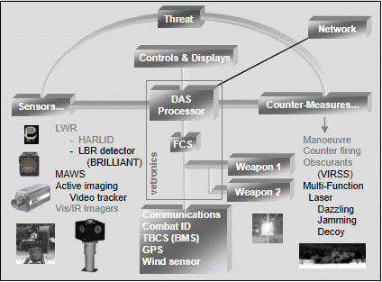
A functional block diagram of the DAS system is given at Figure 1. Sensors and countermeasures of the basic DAS are listed in grey while the components of the second generation DAS are listed in black.

The DAS is based on a classical architecture. The sensors are interfaced to a processor, which in turn is interfaced to the vehicle vetronics and man/machine interface to allow the vehicle commander/gunner to have manual/automatic control over the turret and CM suite. A high-level communication network is also available to control the DAS system through the immersive visualization interface provided by the FAVS project [5].
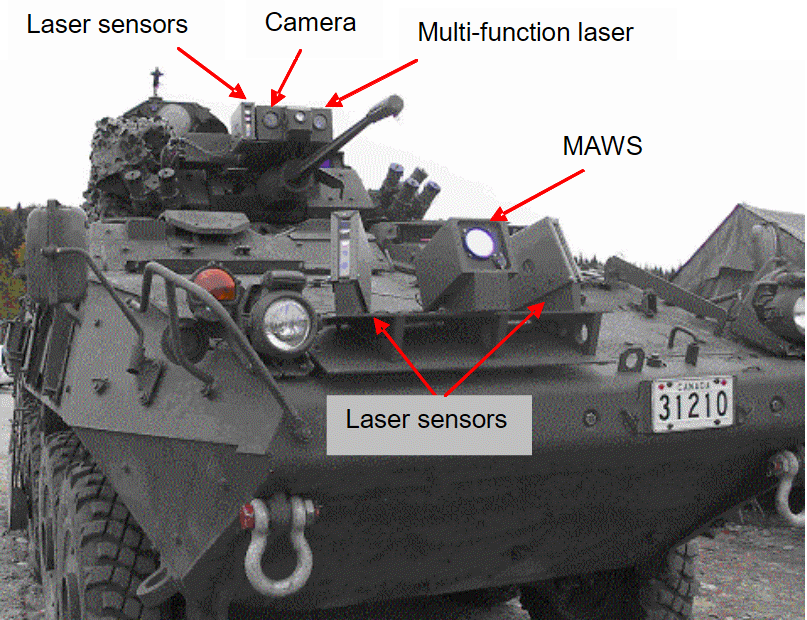
Figure 2 shows a view of the DAS components as integrated on a Canadian LAV III vehicle: two laser sensor modules are installed to cover the front arc of the vehicle. These low-resolution sensors are designed to pick-up the radiation from TD, RF, LW and LBR and to provide a first indication of the threat angular localization. Once cued in the appropriate direction, a second module of laser sensors (low-latency sensors) installed on top of the turret demodulates the laser signal and provides the controls required to get better threat localization and CM selected.
For TD threats, the laser sensors installed on the turret are used to measure the threat signal characteristics and to control the decoy parameters.
For LBR, a technique similar to the one employed in the DRDC-Valcartier BRILLANT (Beam RIder Laser Localization And Neutralization Tracker) system is used [6]. Briefly, the gate of an intensified video camera is synchronized on the pulsed laser signal detected to produce an image of the source. The image is then sent to a video tracker, which controls the position of the turret and gun and aligns them on the threat.
The MAWS sensor is used in a similar fashion as the laser sensors. It gives a first indication (within ±2º) of the threat angular localization and the resolution is improved using the multi-function laser as an illuminator and a video camera to image the firing post optical sight. This method assumes that the firing post used by the enemy can be imaged by retro reflection. In this configuration, the multi-function laser is programmed to illuminate the scene and the retro-reflected light is collected by the laser sensors to synchronize the gate of an intensified video camera. Once an image is obtained, the video tracker is used to lock on to the source and fine-tune the threat angular localization.
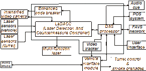
Figure 3 gives a functional block diagram of the second-generation DAS. Each element of the block diagram is described in the following text.
Laser sensors
As discussed previously, the DAS prototype features two kinds of laser sensors: cueing sensors and real-time low-latency sensors. The cueing sensors are installed on the hull and communicate using a standard serial communication protocol (RS-485). The cueing sensors provide a first indication of a threat angular localization.
The real-time low-latency sensors are installed on the turret next to the multi-function laser and are interfaced with the processing electronics using high-speed communication links (TTL). They are used to measure the laser signal characteristics and to provide accurate timing of the incoming signal.
Both sensor heads are designed on the same principle and cover the same waveband and field of view (60º). Wide waveband coverage is obtained using multiple detection channels with interferential filters.
Intensified video camera
The intensified video camera is used to improve the angular localization of a threat using active imaging. Two techniques are available and are referred to as open-loop or closed-loop active imaging. In open loop active imaging, the gate of the camera is synchronized with the signal picked-up by the low latency laser sensors and a prediction algorithm accounts for the short pulse duration and the delays in the detection system. The prediction algorithm operates in a similar fashion as a phase-lock-loop except that the input signal does not have to be periodic. Digital signal processing is used to adapt to a variety of incoming signals.
For closed-loop operation, the multi-function laser is used as an illuminator and the camera is synchronized on its frequency. However, to account for the time of flight of each laser pulse (the distance to and from the target) the prediction algorithm described above is used to trigger the camera gate.
Missile approach warning system (maws)
The MAWS is used to detect the ultraviolet radiation emitted by the plume of a burning missile. The sensor selected for the DAS application is manufactured by EADS and is commercially available under the name of MILDS for Missile Launch Detection System. Because of budget constraints, only one sensor was procured and configured to protect the front right quadrant of the vehicle. According to the specifications, the sensor resolution is ±2º in azimuth and in elevation.
The MAWS is used in a similar way as the cueing laser sensors. It gives an approximate indication of the threat angular localization. High-resolution localization is achieved using closed-loop active imaging.
Enhanced code breaker
The enhanced code breaker was recycled from a project completed at DRDC Valcartier: namely the BRILLIANT project. For the current application, the software was modified to allow open- and closed-loop active imaging as well as real-time regeneration of TD signals as required for the laser decoy. Because of the high processing speed requirement and the real-time constraint, the enhanced code breaker was designed as an independent unit.
Laser detection and countermeasure controller
The Laser Detection and Countermeasure Controller (LaDACC) is the main interface circuit. This circuit monitors the output of the laser-cueing sensors, applies real-time signal-processing algorithms to reduce false alarms and identifies the threats based on the wavelength and the pulse repetition frequency. It is also used to control the operation of the multi-function laser and the operation of the intensified video camera for optimum imaging. It communicates with the DAS processor using a standard serial communication data link (RS-422).
DAS processor
The DAS Processor is the central decision unit. It receives the alarms from the cueing sensors, executes a programmed sequence of events and controls the release of countermeasures according to user configuration. Currently, the DAS processor includes basic processing routines. More work will be required to perform better threat identification, sensor data fusion and countermeasure optimization as well as for handling simultaneous threats. A detailed description of the current DAS processing algorithm is given later on.
Video tracker
The video tracker is an image processing software package developed by Imago Machine Vision Inc. This software analyzes the images produced either by a LBR source or the signal retro-reflected by the optics of a sight and tracks it in real-time. The software is optimized to lock on high-contrast targets as produced by the open- and closed-loop active imaging processes. As previously mentioned, a dedicated processor embedded in the LaDACC circuit automatically matches the gate of the video camera to the characteristics of the laser signal detected. This operation deeply suppresses the background signal and creates high-contrast targets.
Vehicle interface module (vim)
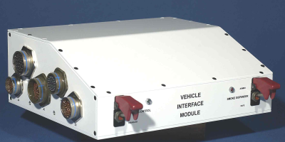
The Vehicle Interface Module connects with the vetronics to control the turret rotation, the main weapon elevation and the release of smoke grenades. Depending on the DAS configuration, the grenades can be released either manually using the LAV III standard control panel or automatically under the DAS control. For security purposes, the VIM connects with the commander and gunner joysticks and requires contact with palm switches to enable the operation. Figure 4 gives a representation of the VIM enclosure.
To make sure that the commander could keep control over the DAS at anytime, a priority was implemented in the DAS functions. The commander was given the highest priority followed by the DAS processor and then the gunner.
User interface
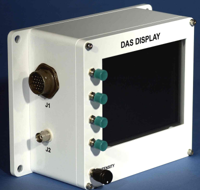
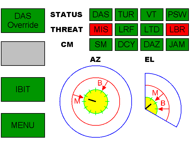
The User Interface consists in a small VGA video display and four reprogrammable switches placed on the left hand part of the enclosure. The function assigned to each switch depends on software and is indicated by labels shown on the screen. Figure 5 gives a representation of the user interface and typical display.
| Auto | Assisted (semi-auto) | Disabled | Manual | |
|---|---|---|---|---|
| Dazzling | ✓ | ✓ | ✓ | |
| Jamming / Active Imaging1 | ✓ | ✓ | ✓ | |
| Decoy | ✓ | ✓ | ✓ | |
| Smoke | ✓ | ✓ | ✓ | |
| Counter- fire | ✓ | ✓ |
Note: 1. Active imaging is used in conjunction with jamming CM.
The user interface is used to set the DAS operation mode, enable/disable the various countermeasures and read the system status. Currently, countermeasures can be programmed either in manual, semi-automatic (assisted) or automatic mode as listed in Table 2.
In manual mode, a user must necessarily press the DAS CM release button to release a countermeasure. In semi-automatic mode, the turret is automatically oriented in the direction of a threat but the DAS waits for user confirmation to release a countermeasure. In auto mode, the turret is automatically oriented in the direction of a threat and a countermeasure is released based on threat identification (see below for threat identification and countermeasure selection). A disabled countermeasure can never be activated, even manually. The commander can always override the DAS and get control over the turret and countermeasures independently of the operating mode.
Favs network
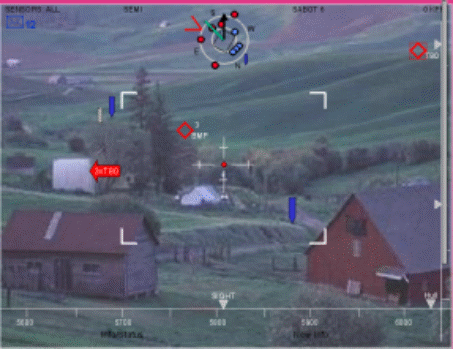
As described previously, the DAS system can be used as a stand-alone unit where the user interface is used to monitor alarms and show system status or it can be connected to the FAVS network and used in conjunction with the other FAVS components. In that manner, the DAS alarms are broadcast on the FAVS network and displayed on the FAVS immersive visualization system. The central top part of Figure 6 shows a typical view of the DAS information as represented on the immersive visualization system. Situational awareness icons are used to show the pointing directions of the hull, turret and sights as well as the location of friendly and enemy vehicles around the vehicle and DAS warnings.
Similarly, the FAVS immersive visualization system can be used to set the DAS operating mode and to control the rotation of the turret through software menus.
Pos system
The POS system consists in a GPS/inertial navigation system. It is used to reference the DAS alarms with respect to North Pole as required by other components of the FAVS project.
Audio cue
An audio cueing system was developed and implemented through the vehicle intercom to alert the crew of a potential danger.
Multi-function laser
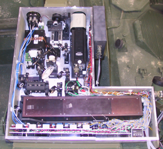
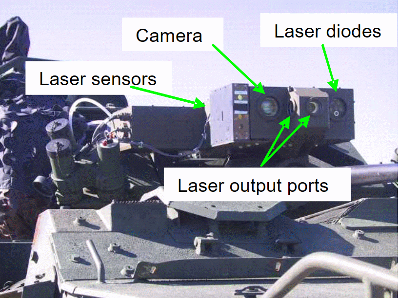
The last component of the block diagram is the multi-function laser. It was designed for laser decoy, laser dazzling and laser jamming and also for active imaging. Other functions such as range finding, target designation, and missile guidance were envisaged but are considered out of the scope of the current development. The core of the multi-function laser is based on a commercial off the shelf Nd:YAG source with appropriate optics to control the beam divergence and output port direction. According to the laser mode of operation, light can emerge either from the front output port or from the side ports located at 90º with respect to the main weapon. In that case, control is available to adjust the laser elevation angle. Figure 7 gives a view of the multi-function laser internal components and its integration on the vehicle.
The variety of wavelengths required for the DAS application is obtained by doubling the frequency of the Nd:YAG source and by merging the beam with the signal obtained from a series of laser diodes operating at selected wavelengths. Frequency doubling is achieved using a non-linear crystal of LBO (lithium triborate). Motor-controlled mirrors are used to send the beam through the crystal or let it go straight to the output. In case of frequency doubling, interferential filters are used to reject unwanted radiation and attenuate it in a light trap. Before being sent to the output, the beam divergence is adjusted by a motor controlled optical system. Any value ranging from approximately 1 mrad up to 4° can be set.
In a basic configuration, the multi-function laser is programmed to create a false target (decoy) of approximately 30 cm diameter at about 5 m from the vehicle. Of course, this ground designation can be walked away from the vehicle to be outside the damage zone of a TD weapon. For dazzling, the multi-function laser is programmed to generate an initial beam divergence of 4º. Divergence is reduced as the threat angular resolution is improved. The same is done in the case of active imaging where the initial beam divergence is set to 4º and reduced as the angular localization of a threat is improved by video tracking. The jammer optics is slightly different. It was designed to match the resolution of the MAWS sensors and is fixed to 4º to match with the resolution of the MAWS.
DAS testing
The operation of the second generation DAS demonstrator was evaluated during a series of technical trials involving threat stimulators such as laser beam rider, laser range finder, laser target designator, and ultraviolet missile plume emulator. For these experiments, the DAS processor was programmed with the basic algorithms shown on Figure 8. Default countermeasures were assigned to each threat as shown in upper case bold characters.
For an LBR threat, the cueing sensors installed on the vehicle were used to sense the signal and produce a coarse approximation of the threat angular localization (±30°). Once alerted, the DAS was programmed to rotate the turret in the direction of the threat and start the open loop active imaging process. The video stream was then used to track on the source and to provide a threat angular localization with pinpoint accuracy (better than 0.1º). Once locked on the threat, the laser dazzler was switched on to break the missile control loop. Other countermeasure could be automatically or manually launched in synchronism if programmed appropriately.
Figure 9 shows a typical image as it appears through the eye-piece of a weapon simulator during an engagement and under eye-safe dazzling.
For TD and RF threats, the DAS was programmed to rotate the turret in the direction of the threat with a resolution ±1° as dictated by the sensor resolution. The DAS assumed that the threat was a RF if a single pulse was detected within 100msec otherwise it was considered as a TD. For a RF threat, the DAS was programmed to release smoke as a primary countermeasure and for a TD threat, the multi-function laser was set to generate a decoy spot at 90º with respect the threat angle. In that configuration, the low-latency laser sensor mounted on the turret was used to pick up the threat modulation and synchronize the decoy. Figure 10 shows an example of the decoy spot projected at close distance from the vehicle.
In the case of non-laser events, the MAWS was used to trigger an alarm with a resolution of about ±2º. The DAS was programmed to rotate the turret in the direction of the threat and then to turn the laser jammer on. In parallel, the multi-function laser was used to perform closed-loop active imaging and to improve the resolution of the threat angular localization. The light retro-reflected from firing post sight optics was collected by the laser sensors and used to synchronize the video camera. The images were then used to feed the video tracker and lock on to the source to improve jammer efficiency. It is worth mentioning that the same laser was used to perform active imaging and dazzling and that both actions were performed at the same time.
Conclusion
Over the last decade, the DAS technology has evolved quite significantly. Initially made of basic detection devices coupled with some kind of audio alarm devices, integrated systems are now available and offer a variety of hard-kill and soft-kill CMs with sophisticated human machine interfaces. The DAS technology is considered mature enough for integration on military vehicles and should be considered as top priority for future acquisition.
This article described an effort made at DRDC Valcartier to develop a second-generation DAS capable of defeating laser threats such as Laser Beam Rider (LBR), TD, RF, and some non-laser Anti-tank Guided Missiles (ATGM) such as second-generation wire-guided missiles. The architecture of the DAS was described in detail and typical results were shown. The DAS succeeded in demonstrating a multi-function laser capability and its operation in realistic scenarios. Future work will include the use of the DAS platform to gather effectiveness data against various threats and to develop advanced models to study the survivability of Canadian military vehicles.
References
[1] A. Cantin, J. Fortin, J. Venter, B.G. Philip, R. Hagen, D. Krieger, and M. Greenley, “Defensive Aids Suite Prototype for Light Armoured Vehicles”, Proceedings of SPIE on Unattended Ground Sensor Technologies and Applications III, Vol. 4393, September 2001, pp. 183–192.
[2] M. Palmarini and J. Rapanotti, “Integrated Development of Light Armored Vehicle Survivability Based on War-gaming Simulators”, Proceedings of SPIE on Enabling Technologies for Simulation Science VIII, Vol. 5423, August 2004, pp. 244–251.
[3] D.H. Titterton, “A Review of the Development of Optical Countermeasures”, Proceedings of SPIE on Technologies for Optical Countermeasures, Vol. 5615, December 2004, pp. 1–15.
[4] C. Acir and M. Middione, “Active Defense Systems (ADS) Program Formerly Integrated Army Active Protection System Program (IAAPS)”, Applied Vehicle Technology (RTO-MP-AVT-108 AC/323 TP/84) Functional and Mechanical Integration of Weapons with Land and Air Vehicles, Williamsburg, VA, USA, June 2004.
[5] G. Pelletier, J. Maheux, J. Fortin, J. Cruickshank, Y. De Villers, and J. Dubois, “Integration of a Sensor Suite on a Light Armoured Vehicle”, Military Sensing Symposium, Gaitherburg, MD, USA, December 2002.
[6] J. Dubois and J. Fortin, “Beam Rider Laser Localization Imaging and Neutralisation Tracker (BRILLIANT)”, Sensors and Electronics Technology (RTO-MP-SET-094), Emerging EO Phenomenology, Berlin, Germany, September 2005.