
Volume 9, Number 2, July 2006
Fitting A High-Performance Gun On A Lighter Platform
- 1 Cranfield University, Defence College of Management and Technology , Shrivenham, Swindon, SN6 8LA, UK.
Abstract
There is great interest in the design and manufacture of lightweight weapon platforms that have capabilities near to existing heavy armour systems. This quest initially started with the requirement to transport field artillery guns via helicopter. With the change in the global situation, the threat has changed and new enemies have developed. This has given birth to rapid deployment forces capable of being effective in a short time. Naturally this force has to be highly mobile (fly light), with its direct-fire weapon platform being able to be delivered to the theatre of operations by C130 or A400 type aircraft. This has imposed serious limitations on the overall weight of a piece of equipment, limiting it to 17–25 tonnes. On the other hand, it is desired that the firepower of this platform matches existing systems. The aim of this paper is to look at some existing guns, having a bore sizes in the region of 105–140 mm, and their mounting on a light platform (17–25 tonnes). Work reported here concentrates on highlighting some of the important constraints that exist and possible ways of dealing with them.
Nomenclature
| cg | Centre of gravity |
|---|---|
| d | Turret ring diameter |
| h | Trunnion height |
| k | Krupps constant = |
| mc | Charge mass |
| mp | Projectile mass |
| MRm | Mass of recoiling components |
| R | Firing load (Trunnions pull) |
| R1, R2 | Reaction as a result of gun fire at the rear and front end support respectively |
| Rmean | Mean trunnions pull |
| ERecoil energy | Recoil energy |
| Rw1, Rw2 | Reaction due to the turret weight at the rear and front end support respectively |
| T | Horizontal distance between the turret ring centre and the trunnion |
| θ | Angle of elevation |
| va | Acoustic velocity |
| vc | Charge velocity |
| vp | Projectile velocity |
| VRm | Velocity of the recoiling parts |
| W | Gun weight |
| x | Distance between the gun cg and the trunnion |
| Z | Recoil travel |
Introduction
There is much interest in the design and manufacture of light weapon platforms having capabilities near to that of existing heavy armour. This quest originally started with the requirement to transport field artillery guns by helicopter, which led to a reduction in weight of about 50%. FH70 weighs about 9,000 kg, while M777, selected for the US Marine Corps, weighs about 4,000 kg.
The modern trend is to develop rapid deployment forces typically consisting of light armour, light guns, and light forces that are able to fly light, yet are armed and armoured heavily to engage effectively with the enemy. Consequently there is a requirement to design and manufacture armoured vehicles, which weigh in the region of 17–25 tonnes, that are C130/A400 transportable, and have the necessary firepower to destroy existing T-series armour. Hence US and UK effort is now concentrated on the Future Combat System (FCS) [1,2] and the Future Rapid Effect System (FRES) programmes respectively [1,3].
The deployment of existing and future fighting vehicles is more likely to favour wheeled platforms to improve ride, economy of fuel, and dash speed. This has a direct impact on vehicle dimensions, as more space is required to accommodate a suitable size and the number of wheels. On the other hand, the inclusion of wheels will increase platform height. Although not a UK requirement, it may also be desirable for the vehicle to have an amphibious capability—this has a direct impact on mass in order to improve its buoyancy. Rapid reaction force demands that these vehicles can be transported into theatre as soon as possible, which means they will either be transported in C130s or A400s, which puts serious and strict limitations on mass, width, and height. As a result, existing heavy armour that weighs approximately 60–70 tonnes and has 18.5 cubic metres of internal volume must be reduced to approximately 17–25 tonnes, having an internal volume of 11 cubic metres. This means that the available space has reduced by 40%. Nevertheless, the requirements of protection and firepower remain the same. Light vehicles having thin armour must rely more on active protection, or be designed so that additional armour can be added prior to participation in the action. It is also desirable to have the same firepower capability or, better still, to improve it.
The aim of this paper is to look at some of the existing guns, with a bore size in the range of 105–140 mm, and their ability to be mounted on a light platform (17–25 tonnes).
Work reported here concentrates on highlighting some of the important constraints that exist and possible ways to deal with them. Generally, the gun is mounted in a turret providing protection to the crew; this can be considered the conventional method. In the past, and also recently, some manufacturers have tried mounting guns, without a turret, externally above the platform hull. This allows the gun to have a longer recoil stroke. In addition, the crew is located inside the hull. This paper also identifies advantages and disadvantages of both approaches.
| 1950– 1960 | 1970– 1980 | 1990– 2000+ | 2005 | |
|---|---|---|---|---|
| Yield Strength MPa | 850–900 | 1,050 | 1,250 | 1,300+ |
| Design Pressure (DP) MPa | 525 | 680 | 740 | 750 |
| Fatigue DP MPa | 490 | 670 | 700 | 700 |
Anticipated protection
Most western ammunition manufacturers claim to achieve a penetration performance of approximately 650 mm in RHA at 2,000 m [4] from their primary kinetic-energy Armoured Piercing Fin Stabilised Discarding Sabot (APFSDS) round. It is thought that the penetration capability of future rounds of this type may be enhanced by 30% by the use of novel design, better materials, improved manufacturing processes, and improved (enhanced) strike velocities. As a result one can expect an opposing Main Battle Tank to have frontal armour whose line-of-sight thickness will be of the order of 900 mm Rolled Homogeneous Armour (RHA) equivalent [5]. To defeat such a target one needs to take account of currently available guns and their performance.
Lethality and performance of available guns
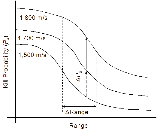
At the end of World War II, a typical armoured vehicle would be armed with an 80-mm gun. Since then the trend has clearly moved towards higher calibres, with 105-mm guns being the norm on armoured vehicles. Royal Ordnance developed and manufactured the L7, 105-mm tank gun in the 1950s and a number of its variants were produced under licence by US, Germany, India, Pakistan, Sweden, and Egypt. In the 1960s, because of better kill probability and range as shown in Figure 1, work began on a 120-mm rifled barrel in the UK and a 120-mm smooth-bore barrel in Germany. The outcome was the L11, 120-mm rifled barrel, designed and developed by Royal Ordnance and the L-44, a 120-mm smooth-bore barrel designed and developed by Rheinmetall. To further improve its performance, Royal Ordnance and Rheinmetall have upgraded both these guns to L30 and L-55 respectively. The L30 barrel is being fitted on Challenger 2 and the L-55 has been installed on Leopard 2. Apart from India, for their Arjun tank, the UK is the only country currently manufacturing a rifled barrel. On the other hand, the L-44 gun is used by NATO countries and manufactured under licence by US, Sweden, SA, and Israel [6]. It is believed that these guns can sustain a firing pressure of up to 700 MPa (see Appendix A). With the improvement in material technology, the Swiss Defence manufacturer RUAG has developed a 120-mm smooth-bore Compact Tank Gun (CTG) that was originally developed to up-gun the 105-mm Pz 68 series Main Battle Tanks (MBTs) of the Swiss Army. It is claimed that this gun can withstand pressures up to approximately 740 MPa [7]. In order to withstand the ever-increasing firing load, barrel material has developed in strength and improved fatigue life as shown in Table 1.
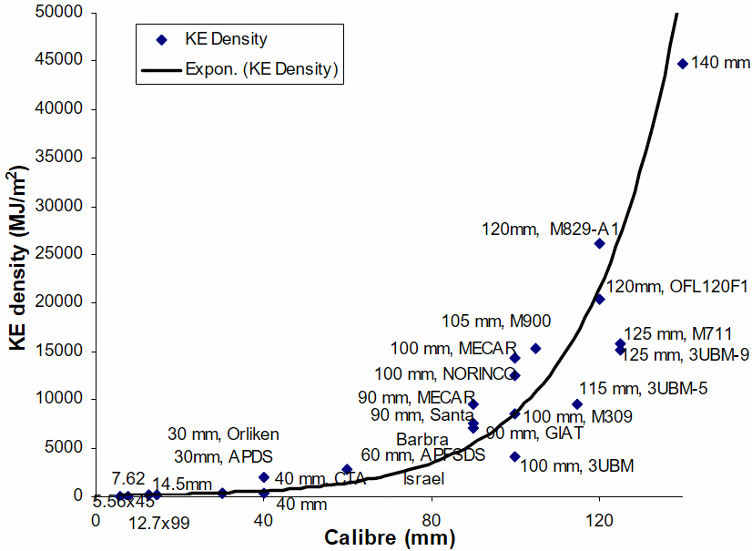
More recently CTG has been installed by the Jordanian King Abdullah II Design and Development Bureau (KADDB) in an upgraded M60 series MBT, and the Falcon turret system for their Challenger 1. The UK is considering replacing their 120-mm L30 rifled gun with a NATO standard 120-mm smooth-bore gun for which the CTG and the L-55 are contenders. It is claimed that this option has significant longer-term advantages, including interoperability with friendly countries equipped with the M1A1/M1A2 Abrams, Leopard 2, and Leclerc tanks. Moreover, UK will also be able to take advantage of the significant investments being made in 120-mm tank ammunition by such countries as France and Germany. RUAG has also demonstrated and test-fired a 140-mm smooth bore gun [9]. In addition, the ability to project a higher kinetic-energy-density round favours the use of a large-calibre gun, as shown in Figure 2.
Recently, Rheinmetall has revived its 105-mm gun technology (smooth-bore) [10] for lighter platforms, giving a performance equal to that of a 120-mm gun, using improved surface-coated double-base solid propellant, optionally supplemented by electrothermal-chemical technology. The use of suitable energetic material to give more energy per unit mass, having a suitable propellant shape to yield the desired burning rate (by providing suitable propellant to chamber volume to control the burning) and the addition of suitable additives have resulted in an efficient gun system. Appendix A highlights the performance of some of the available systems. It is evident that existing systems are capable of defeating the current armour threat.
If a plot of first-time kill probability is extrapolated for 140-mm gun as shown in Figure 1, it can be seen that 140-mm gun will out-perform a 120-mm gun as the 120-mm gun out-performs a 105-mm gun. A 120-mm round will achieve a given penetration against enemy armour at a greater range than a 105-mm round or, for a given range, 120-mm will give better penetration.
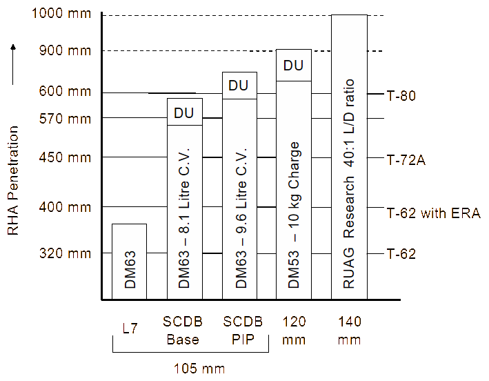
Figure 3 indicates that an L7 gun firing a DM63 type projectile is able to perforate T62 type armour [5,11]. However it fails to perforate if the T62 has Kontakt 5 ERA, or it is fired on T72-type armour. Variants of 105-mm developed by Rheinmetall have the capability to perforate existing armour. This has been achieved by increasing charge mass and chamber volume (C.V) and suitably shaping and sizing the energetic propellant yielding more energy per unit mass. This propellant has been designed by Nitro Chemie and is known as surface-coated doubled-base propellant (SCDB). It can be seen that existing 120-mm guns give a similar performance with the available ammunition. With similar improvements, a 120-mm gun performance can be further enhanced. RUAG, with their 140-mm research gun and 120-mm CTG gun have demonstrated a penetration capability of 1,000 mm and 900 mm respectively, using a special round with a slenderness ratio of 40:1 [5]. Rheinmetall, as a private venture, has developed a new 120-mm low-recoil smooth-bore tank gun (LLRSB) using high-strength steel.
All of the following can result in increased muzzle velocity:
- more propellant;
- more energetic propellant;
- longer barrel;
- larger bore; and
- lighter round (reduced parasitic mass).
A combination of these factors has resulted in an optimised performance and is discussed in detail by Bennett [12]. These factors led to the use of a longer barrel length (for example, the length of L-55 is 1.35 m longer than L-44). In addition, the propellant mass along with its energy contents were also increased, such as the L23 round (fired from L11 gun) which contains 6.6 kg of triple-base propellant in stick form as compared to the L26 (fired from L30 gun) which contains 8 kg of RDX propellant in stick form. On the other hand DM43 contains 6.9 kg of double-base propellant while DM53 contains 8.9 kg of surface-coated double-base extruded propellant. Extruding increases the loading density. To maintain low peak pressure over a longer duration, methods to control the propellant burning, such as grain impregnation using blast oil or deterring the burning surface, have been successfully used to enhance the muzzle kinetic energy (MKE) for medium-calibre guns [13] and is under investigation for large-calibre guns. An alternative method to control energy release is to use layered propellant, consisting of lower-burning-rate propellant on the outside surface, which burns up to the time when maximum pressure occurs, followed by a high-burning-rate propellant in the core. Practically, layered propellant is difficult to produce. Consolidating the propellant using salvation can also increase loading density. Figure 4 summarises the enhancement in gun performance over the years [14]. In addition, further enhancement has been achieved by reducing the parasitic mass of KE round by firing a lighter sabot as in the M829A2, KE round. Currently, propellants yielding peak pressures that are independent of initial temperature state are under development (such as DM63). This will lead to better and lighter gun barrel design. Even further enhancement can be achieved by increasing the bore size to, for example, 140 mm. However, the implication for ammunition handling and the questionable need for such a system have delayed 140-mm gun development. However, it is reported that both the Chinese and Russians are working on 140-mm guns [15].
![Gun performance improvement [13].](/journals/journal-of-battlefield-technology/volume-09/issue-02/assets/9-2-2-hameed/figures/figure04.gif)
Platform stability
One of the key issues which arises from the fitting of large-calibre gun on lightweight platforms is that of stability. We can gain an insight into the problem by considering the conservation of momentum during firing: momentum of shot and propellant gases just before the shot exit + impulse due to gas action after the shot exit = momentum of recoiling mass just after gas action.
or,
where .
Consequently:
The recoil energy is given by:
Some energy is dissipated as heat in the buffer during recoil and by overcoming friction, whilst the remainder is stored in the recuperator as elastic strain energy. Collectively the force of retardation is known as the recoil force, or trunnion pull, as shown in Figure 5. It is transmitted through the cradle and trunnions to the vehicle structure. Thus the trunnion and structure must be strong enough to withstand this recoil force. In addition, the over-turning moment caused by this force must not de-stabilise the platform. Figure 6 also demonstrates how these forces might vary with distance during recoil. Note that, initially, buffer force is deliberately kept small, so that there is minimum disturbance to the barrel before the shot exits. The initial recuperator force must be at least sufficient to hold the gun in its firing position at maximum elevation.
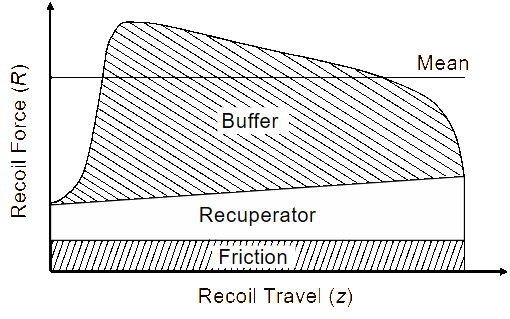
The recoil distance varies from about 300–400 mm in MBTs and from 1–2 m for towed guns. Recently, tank guns having recoil length up to 600 mm have been installed on some light vehicles such as LAV, Rooikat and Centauro. Appendix A also gives an approximate length of recoil of some of the available systems. Since the recoil energy of the recoiling mass, (ERecoil energy), is either dissipated as heat in the buffer, doing work against friction or stored in the recuperator, we can equate it to the area under the recoil force-recoil stroke graph (Figure 5). By defining mean recoil force Rmean, the area can be treated as a rectangle, giving:
Substituting Equation (3) and (4) into Equation (5), we get:
It follows that the mean trunnion pull reduces with the increase in length of recoil and barrel mass, and it increases with the increase in muzzle velocity, projectile mass and charge mass. It is self evident that the continuing requirement for improved performance will increase mean trunnion pull and an out-of-balance force which may affect vehicle stability. This is a serious problem in lighter platforms. Trunnion pull can be reduced by 30–40%, if a muzzle brake is used [16]. A muzzle brake having an efficiency higher than this will cause back blast, vision destruction, and also possible vehicle damage. At present trunnion pull has been kept below the limiting values for the lighter platforms by increasing the length of recoil to the maximum permissible length.
Fitting guns
In order to fit the gun, the following spatial considerations are important:
- mounting location and turret vehicle interaction,
- inboard barrel length and swept volume,
- breech opening and recoil consideration,
- ammunition handling and stowage, and
- crew activities.
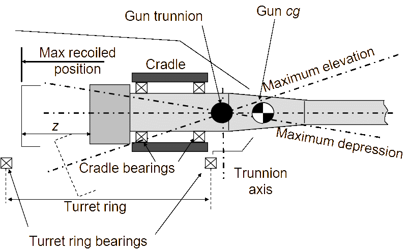
The mounting location affects the overall length of the equipment, maximum gun depression angle, the platform’s tactical height, and the position of its centre of gravity (cg). In certain cases it may affect trunnion height. Most of the existing platforms (MBTs) have the gun mounted in the middle with driver at the front and the engine in the rear. Certain AFVs have retro-fitted a tank gun in the available space, which by coincidence happens to be in the middle. Examples include Alvis, UK P90 having a 90-mm gun, Centauro, Rooikat and Cadillac gage LAV-600 having a 105-mm LRF gun, and Centauro 8×8, HITFACT120 having a 120-mm gun mounted on it. The size of the turret increases with the size of the gun and most of the available space for the crew is taken up by the gun and other ancillary components in the AFV. In addition, to support the battle, the vehicle one must have adequate ammunition stowed and accessible onboard, limiting the space available for the crew. For accuracy of fire, it is important for the tank to have a balanced and stabilised gun. Also to reduce the load on the gun-stabilising systems, generally the gun cg is slightly offset from the trunnion. This helps the system to maintain stability effectively when on the move. This configuration leads to increased inboard volume as shown in Figure 6.
Depending upon the exact location of the trunnion, it also affects the overall turret height for the gun to recoil when firing at maximum angle of depression. This also reduces the working space available behind the gun. On the other hand this configuration is favoured because of the reduced gun overhang, reduced barrel droop, and reduced vibration, which are important for accuracy and consistency of fire in the direct-fire weapon system.
Alternatively, to overcome the lack of manoeuvring space for a four-man crew, certain designs have been offered with an autoloader by replacing the third crew member who generally acts as a loader (such as Centauro 8×8 and HITFACT). This may increase space for the remaining two members but creates complexities as a result of automation and, in certain cases, may reduce rate-of-fire. This arrangement may pose extra stress on the remaining crew for the housekeeping tasks they need to perform to maintain the vehicle for a 24-hour battle day.
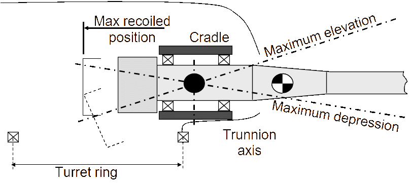
In the case of indirect-fire weapon systems, the trunnions are located near the middle of the cradle front and rear bearings, and the gun cg is ahead of the trunnion location as shown in Figure 7. This allows the gun to have a longer recoil length and enables the high angle of fire required by an indirect-fire gun. This also allows reasonable space behind the gun for the human loader to load the round manually, which is fed directly from the ammunition pallets outside the gun. Because of the rate and the number of rounds to be fired, auto-loaders are preferred in an indirect-fire weapon system.
Typically, turret ring diameter is about 2–2.5 m, as shown in Figure 8. To avoid unbalanced forces acting on the ring, the trunnion position is kept as near as possible to the turret ring. As a consequence, the ordnance and cradle occupy approximately 1.4–1.6 m inside the turret. This leaves approximately 400–700 mm for the gun to recoil.
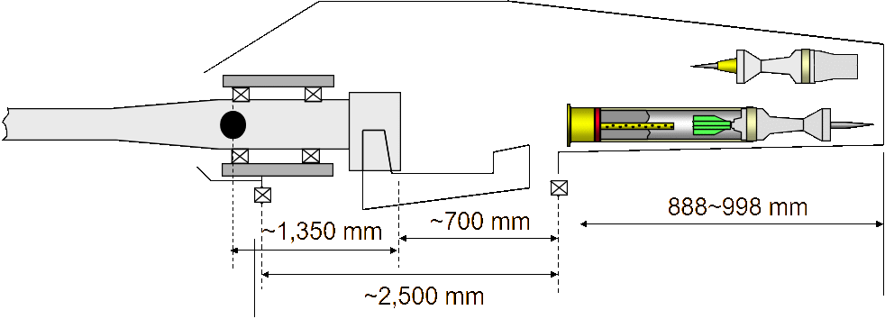
To avoid unnecessary wear of the turret ring, the turret is statically balanced about its traversing axis. Thus to balance the weight of the frontal armour and the gun, the turret rear is extended to have a bustle, which is generally used for ammunition stowage, as shown in Figure 8, or accommodating ancillary kit such as NBC or communication equipment.
The average handling weight of a 105-mm and a 120-mm complete round has been 18 kg and 21 kg respectively, while for 115-mm and 125-mm projectiles it is around 20 kg and 22 kg respectively. A 120-mm single-piece brass cartridge case ammunition would have a length of approximately 1.32 m (see D in Figure 9).
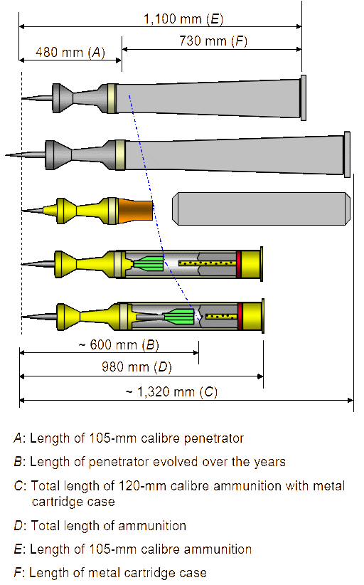
The use of combustible cartridge cases for 120-mm (Figure 9) and 125-mm guns has kept the increase in the overall weight of the round small, which helps to avoid unnecessary crew fatigue. The overall round length is limited by the available loading and stowage space in the bustle or within the hull (for example, for the current 105-mm and 120-mm round, this has been around 900 to 1,000 mm as shown in Figure 9). Current NATO rounds have a longer penetrator extending rearwards into the cartridge case (see B in Figure 9); there is a limit to this protrusion as it will reduce propellant space and will require dense packing causing ignition difficulties. The UK and the former Soviet States use separate ammunition. In the case of the UK, the inert penetrator is stowed in the bustle, while the propellant is stowed in the hull. The T-series ammunition has an incremental propelling charge with the projectile assembly in addition to the main charge and is stowed in the carousel of its autoloader.
Under normal operating conditions, the turret ring and hull roof should be able to withstand the firing load. The hull roof should be strong and stiff enough not to bend unduly and cause unnecessary jamming and/or wear of turret bearings. This may require detailed stress analysis. However, for the purpose of estimation and to highlight the way loading can affect hull structure, it is assumed that the gun is simply supported at the two ends located across the diameter of a circular ring, as shown in Figure 10. Thus the magnitude of reaction force can be evaluated as follows:
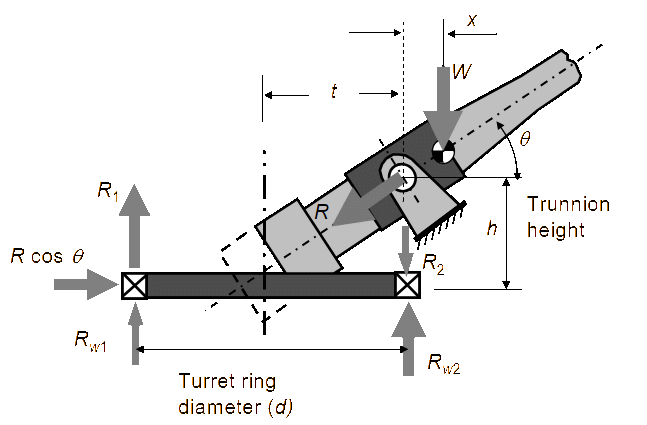
Additionally, upon firing, the two end supports will also bear the firing load (R) as:
The loads on the turret ring (as shown in Figure 10) from Equation (9) will be quite large and will not be equal. This could lead to distortion and even buckling of the roof structure.
Turret design
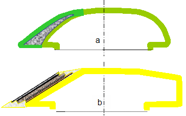
The modern day tank turret has evolved from T-34 introduced by the soviets in 1939. Germans, French, British and finally the US followed the same manufacturing style [17,18] by casting steel. To enhance armour protection, especially against HEAT rounds, it is believed that a cavity, on each side of the gun, on the front of the turret shell as shown in Figure 11a of T-64 was introduced to accommodate glass fibre and ceramic known as corundum. This seems to be the first generation of advanced armour [19]. Similarly, fused silica was used in American test turrets, T-95 program [20]. This turret design is distinguished by a high obliquity quasi-elliptical configuration, which provides maximum strength, rigidity and ballistic protection. In the later Soviet turret design, cavities were introduced while incorporating the same basic armour design, being low, sleek and having excellent ballistic obliquity. This arrangement prohibits bustle extension. Additionally, five-layered laminated armour was fitted to the glacis [21]. On the other hand, after the termination of joint German-American MBT-70 program and due to the lessons learnt from the Arab-Israeli war, Western manufacturers started all-welded-steel armour construction to which layers of composite armour can be added by either bolting, welding or mounting in slots as shown in Figure 11b. This configuration results in a flatter turret design as found in M1, Leopard 2 and Leclerc. Prior to all-welded structures, Israel had used a combination of cast armour with welded add-on armour at the front of the turret structure in their Merkava, Mk 1, MBT. During the past 20–25 years, the threat to the tank, evolving from technological development has progressed at a faster rate than the technologies related to tank armour. As a result, modular armour that can be added on to the main structure has become the preferred choice as a new system can easily replace the old as it becomes available. Also the T-90, of Chinese origin, the Arjun MBT of India, and the Type 90 MBT of Japan have all steel-welded turret configurations.
Examples
MBTs such as M1A2-Abrams, Challenger 2, Leopard 2, Merkava and Leclerc are fielded with 120-mm guns while T72, T80, T84, and T90 have 125-mm direct fire guns mounted on them. Due to the better performance of 120-mm tank ammunition, to demonstrate the compatibility and capture the market, some nations from Former Soviet States have developed 120-mm gun systems and have mounted them on their T72, T80, and T84 for export to prospective buyers.
Based on the current ammunition, and referring to Figure 10 and Equation (6), firing loads of the order of 600 kN act at the gun trunnions of the above-mentioned vehicles with the length of recoil travel of approximately 320–340 mm. The size and the weight of these vehicles are such that the stability of the platform is not of concern. However the size of the trunnion bearing affects the turret width, hence low recoil force is preferred. Medium (CV90) and light platforms (LAVs and AFVs) will be highly unstable, requiring longer recoil travel to maintain firing loads of the order of 250 kN and 180 kN respectively. Centauro 8×8 (HITFACT 120) and CV90 guns are designed to have a length of recoil travel equal to 550 mm and 500 mm respectively. Alternatively, to maintain low recoil forces, some manufacturers are, in combination, using guns with shorter barrel length. The RUAG 120-mm gun mounted on CV90 is 50 calibre long, while the HITFACT 120 is of 45 calibre. These guns have been mounted in a conventional turreted configuration as shown in Figure 12. This configuration allows comparatively low trunnion and turret height, maximum recoil travel of 600 mm and allows the commander to keep his ‘head out’ to sense and judge the battlefield. In addition to crew protection, a turret provides protection to the breech, recoil and the other gun systems and allows either manual or auto-loading of ammunition due to the direct crew access to the breech and firing system. However, the turret represents a large target. In an effort to reduce the turret height, a number of suggestions have been made:

- Reducing the head room by loading the gun from a seated position (or replacing man with an auto loader) [22].
- Restricting the maximum angle of gun depression or providing a flap hatch in the roof to accommodate gun recoil when breech moves upward past (for example, in the Leopard 1 upgrade and the French-German tank programme MBT-90) [23].
- Reducing the size of the crew operating the tank during combat.
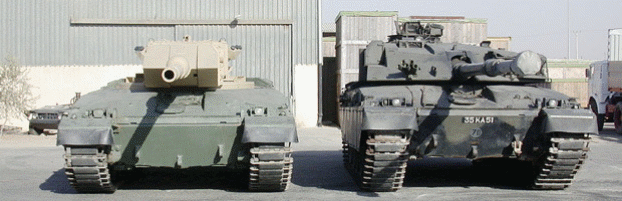
This has led to suggestions of relocating the crew in the hull thereby increasing their protection and leaving the main armament to be traversed in an unmanned turret (or sort of external gun). The former can be designed with frontal trunnions, similar to conventional system, which can allow the gun breech to descend into the hull for reloading either via an autoloader or manually should the system malfunction. This scheme provides armour protection to its gun system. Originally this design was proposed in the American test-bed vehicle in 80s, and recently the same concept was used by the Jordanian Army in the Falcon II turret while upgrading their Challenger 1 as shown in Figure 13. The ammunition magazine was located in the turret basket in the former concept, while the autoloader, including the magazine, was located in the bustle of the later concept. This concept has the advantage of increasing the crew protection and overall vehicle survivability due to reduced frontal area as shown in Figure 13 and lower silhouette. In this configuration, recoil travel is still restricted, due to the possibility of the gun recoiling against the turret ring, thus limiting the trunnion pull which acts at the gun mount. Also, the lack of commander’s direct vision from the highest point, and crew separation due to gun intrusion is not favoured [24,25] by most tank commanders.
The laws of physics dictate that even longer recoil travel is required to mount a high-pressure, high-performance gun on a light platform (15–20 tonnes). This will lead to an externally mounted gun either mounted on a post, with centred trunnions like the Swedish UDES 20, or a system like the General Dynamics LPT gun with rear trunnions mounted on a saddle mount. This configuration will allow longer recoil travel (General Motors, LPT Assault gun with 500 mm of recoil travel yields a trunnion pull of approximately 250 kN and 180 kN, with 750 mm of recoil travel) as shown in Figure 14. An external gun concept is eye-catching and psychologically attracts viewers because of the low frontal area, and a direct view of a big gun, which is taken as a sign of power. An externally mounted gun has the following advantages:

- It allows for lethality growth and, being a modular design, lends itself for mid-life upgrade without affecting the other components of the system. The gun can be mounted on a common chassis with minimum modifications.
- If the gun has rear trunnions, it can fire at high angles of elevation, though trunnion height will increase if required to fire at the desired angles of depression when compared with existing conventional configuration.
- The arrangement reduces the frontal area and the overall combat weight. Being lightweight, it can have high power-to-weight ratio and, due to its agility, will have better survivability.
- The configuration has an imposing presence.
The lack of a commander’s vision from the highest point, the exposure of the complete gun system, the complexity and sophistication of the auto-loader may affect the overall system’s effectiveness and reliability. On the other hand, advancement in video visualisation and improvement in resolution will allow the crew-in-hull configuration with a saving of up to 30% in weight.
Conclusion
The mounting of a gun of the required capability on a light- or medium-weight platform presents a significant challenge to the designer. It is probable that the solution lies in the externally mounted gun concept, if a high-performance gun is to be mounted on a light platform. The time has come to design turretless guns that are controlled and fed by well-designed ammunition-handling systems. Obviously any design that is finally selected must undergo rigorous tests and trials.
Acknowledgements
The authors would like to thank Mr Mike D. Bennett. They would also like to thank Dr Ralf-Joachim Herrmann, Dr Berthold Baumann, Dr Eckehard Bohnsack, and Dr K.A. Kratzsch of Rheinmetall W&M for presentations of their products, Mr Guy Fairweather of BAE Systems for his kind suggestions and Dr B. Vogelsanger of NitroChemie Wimmis AG for his presentation on their products.
References
[1] “Executive Overview”, Jane’s Armour and Artillery, www.janes.com, Date posted: 7 May 2003.
[2] “Analysis/Executive Overview”, Jane’s Armour and Artillery Upgrades, www.janes.com, Date posted: 8 Sep 2003.
[3] R. Pengelley, “Future Rapid Effect System Leads British Forces’ Transformation”, International Defence Review, www.janes.com, 21 Aug 2003.
[4] “Ammunition Hand Book”, Jane’s Information Group Limited, ninth edition, Sentinel House, 163 Brighton Road, Surrey, CR5 2YH, UK, 2000.
[5] W. Lanz, “140 mm Gun and Ammunition System”, AFV Symposium, Cranfield University, UK, 1998.
[6] R. Pengelley, “120mm Smoothbore Developers vie for Leadership in Light Weight and Lethality”, Jane’s International Defence Review, www.janes.com, May 2004.
[7] “RUAG Land System 120 mm Compact Tank Gun”, Jane’s Armour and Artillery Upgrades, www.janes.com.
[8] Various sources.
[9] “RUAG Land System 140 mm Compact Tank Gun”, Jane’s Armour and Artillery Upgrades, www.janes.com, 9 Apr 2003.
[10] R. Pengelley, “The Big Battalions Rule”, International Defense Review, www.janes.com, 11 Sep 2002.
[11] F.C. Foss, “105mm Smoothbore Gun Awaits Green Light”, Jane’s Defence Weekly, Vol. 39, No. 1, 8 Jan 2003.
[12] M.D. Bennett, Defence Technology Course Lecture Notes on Direct Fire Gun Performance, Defence Academy of UK, RMCS, Cranfield University, Shrivenham, Swindon, SN6 8LA, 1999.
[13] B. Vogelsanger, and K. Ryf, EI-Technology—The Key for High Performance Propulsion Design, Nitro Chemie Wimmis AG, CH-3752 WIMMIS, Switzerland, Tel: 33 22813 00.
[14] F.W. Oberle, and D.B. Goodell, “The Role of Electrothermal-Chemical (ETC) Gun Propulsion in Enhancing Direct-fire Gun Lethality”, 16th International Symposium on Ballistics, San Francisco, CA, pp. 59–69, 23–28 Sep 1996.
[15] F.F. Christopher, “Large-Calibre Super Tank being Developed in China”, Jane's Defence Weekly, www.janes.com, 16 Apr 2003.
[16] A presentation given to author by Dr Ralf-Joachim Herrmann and Dr Eckehard Bohnsack of Rheinmetall-Wm, Unterlus, Germany, 27 Apr 2004.
[17] A.D. Starry, “Tank Design: Ours and Theirs, Part II, 1940–1945”, Armor, pp. 5–7, Nov–Dec 1975.
[18] D.C. Bradley, “Future Close Combat Vehicles”, Armor, pp. 36–41, Jan–Feb 1981.
[19] M.J. Warford, “T64, IT 122 and IT 130: The Soviet Advantage”, Armor, pp. 40–43, Sep–Oct 1985.
[20] M.J. Warford, “Soviet-Russian Tank Turret Armor: The Cold War Shell-Game”, Armor, pp. 16–17, Jul–Aug 1999.
[21] M.J. Warford, “The Russian T90/T90S Tank: An Old Dog with some Dangerous New tricks”, Armor, pp. 6–9, Mar–Apr 1995.
[22] R. Fletcher, “From the External Gun to the Hybrid Tank”, Armor, pp. 22–25, Nov–Dec 1996.
[23] R.Hilmes, “Modern German Tank Development, 1995–2000”, Armor, pp. 16–21, Jan–Feb 2001.
[24] D. Loughlin, “The External Gun Turret: Often a Bridesmaid, Never a Bride”, Armor, pp. 20–22, Jan–Feb 1996.
[25] R. Fletcher, “Trunnions on the Move”, Armor, pp. 33–43, Jan–Feb 1986.