
Volume 9, Number 2, July 2006
Numerical Study Of The Heat Exchanges Occurring In A 120-mm Chromium-Coated Gun Barrel And Comparison With Experimental Results
- 1 Giat Industries, 7 route de Guerry 18023 Bourges Cedex, FRANCE.
Abstract
The MECCAD code has been developed within Giat Industries to predict the heating and the cooling of a gun barrel during a burst. When the projectile moves in the barrel we calculate the convective parietal heat flux by using the Reynolds-Colburn analogy. After the projectile exit, the discharge of the propellant gas in the barrel is modelled with enough accuracy to respect the physics of the phenomena. The main difficulty is to predict the inner flow when the muzzle conditions are subsonic. The results allowed determination of the parameters of the expansion laws, which were used as the inputs of the cooling convective and radiative heat exchange laws. Thus, it is possible to calculate the initial barrel temperature just before a new firing. 120-mm gun calculations with MECCAD code were carried out for one shot with Armour Piercing Fin Stabilized Discarding Sabot (APFS-DS). The comparison with parietal temperature measurements shows a good agreement (especially near the forcing cone).
Introduction
During the last few years, with gun barrel wear problems, much attention has been focused on the heat exchanges occurring during and after a shot in a gun barrel (heating and cooling phases) [1].
This paper deals with the calculation of the heat exchanges occurring during these two phases in a 120-mm chromium-coated gun barrel with Armour Piercing Fin Stabilized Discarding Sabot (APFS-DS).
When the projectile moves in the barrel we calculate the convective parietal heat flux by using the Reynolds-Colburn analogy. The boundary layer is estimated by an integral method.
After the projectile exit, if the flow is supersonic or sonic at the muzzle, the discharge of a propellant gas in the barrel is calculated, using a one-dimensional unsteady numerical code, based on the characteristics method, according to a pull-push piston analogy. The results allow determination of the parameters of the expansion laws, which are used as the inputs of the cooling heat exchange laws. Thus, it is possible to calculate the initial barrel temperature just before a new firing. During the cooling phase, the radiative heat exchange is as important as the convective one.
Then, a numerical parametric study is conducted with MECCAD code to determine the sensitivity of the barrel heating and cooling to the temperature profile inside the boundary layer and to the chromium thermal properties.
The results of the 120-mm gun calculations with MECCAD code are then compared with experimental measurements [2]; BRL’s (Ballistics Research Laboratory) thermocouples were located in three sections along the barrel and between 250 µm and 900 µm from the inner barrel wall. The comparison at the same cross section inside the barrel, and at the same sensor locations, shows a good agreement between calculations and measurements (especially near the forcing cone).
Pressure and temperature measurements in a 120-mm calibre chromium testing gun tube [2]
Sensors location
Five pressure sensors (piezoelectric ones) were located longitudinally respectively at 80, 470, 1,025, 2,750 and 5,000 mm from the breech.
Internal temperatures were measured using intrinsic iron/constantan thermoelectric sensors. This measurement procedure presents a very short response time and is validated for medium-calibre guns (see [1]):
Fifteen thermo-couples were located longitudinally:
- five in a cross section located at 1,300 mm from the breech,
- five at 4,200 mm from the breech, and
- five at 6,120 mm from the breech.
Due to the very steep temperature gradients present near the inner surface of the gun barrel, the measuring holes are drilled so as to set the sensors at the shortest distance from this surface. For each cross section we need five thermocouples located at three depths. The two holes of each section which are at the shortest distances from the inner surface of the gun barrel are duplicated to make sure of a thermo-couple signal at these depths. For inverse conduction calculation method only two depths are used, the third depth that is the farthest from the inner wall is used for validation tests. Upstream sensors should be as close as possible to the inner surface of the gun barrel. The closest distances that could be practically located without destruction due to internal pressure are respectively 630, 370 and 270 µm with an accuracy of ±10 µm. To assist with machining holes and to be aware of thicknesses, we used a very high frequency ultrasonic sensor inside the tube.
The thermoelectric sensors are constituted by 0.25 mm diameter constantan wires welded at the bottom of a 1.65-mm diameter flat-bottom hole. A precision Teflon guide is used to ensure that the measuring wires are located exactly in the centre of the drilled holes. The steel-constantan junction is obtained by using a capacitor-discharge technique. Once the welding is assured, the guide is retired and replaced by glue. The iron wire is welded at the outer surface of the tube. The thermoelectric sensor power is about 52 µV/°C.
Data acquisition system
The sampling frequency of the Nicolet data acquisition system used is 10 kHz, which enables the recording of the heating and the cooling phases.
Tests conditions
The tests were carried out at ETBS (Etablissement Technique de Bourges) at Bourges on February 1999, on a 120-mm calibre test gun barrel. The tube length is about 6 m; the inner surface of the tube is protected by a chromium coating. There was no wear on this tube before the tests. The shots were realized with inert APFS-DS of about 7 kg (without and with 230 g of wear-reducing additives in the propellant charge). We used double propellant charges.
During the tests, which are usually reproducible, we saw:
- breakages of some thermocouples caused by vibrations, by the muzzle break blow;
- thermocouple signals perturbed by the 50 Hz local circuit supply frequencies; and
- during the slow-cooling phase signals were perturbed by a 0.2-Hz frequency.
Figure 1 shows the gas pressure measured at 2,750 mm from the breech.
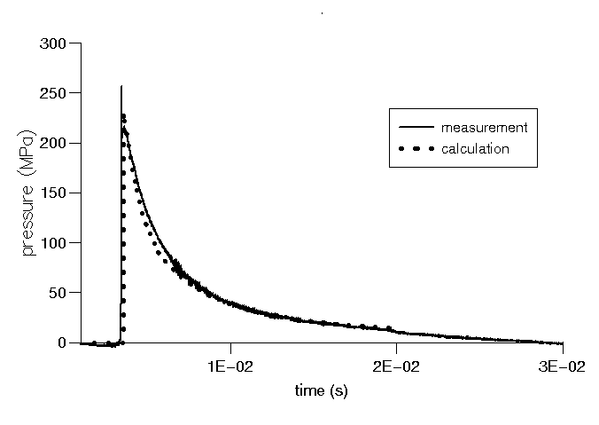
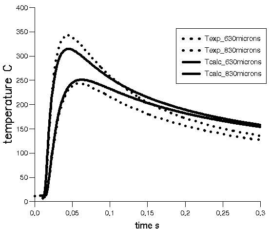
Figure 4 shows the numerically filtered (smoothing method) temperatures measured in the section near the forcing cone (1,300 mm from the breech).
Numerical study of the heat exchanges occurring in a 120mm chromium coated gun barrel
Heat exchanges occurring during the cooling phase
Here, we address the cooling heat exchanges, which are used in THETA code [3]. The gas discharge is treated in the next paragraph. This code calculates (one- or two-dimensionally) the temperature everywhere in the barrel, at any time of its heating and of its cooling, during a burst. The calculation is based on a heat fluxes balances method using one- and two-dimensional heat balances realized on each elementary mesh of the barrel. The numerical integration used the Gear schemes, and an iterative method for the two-dimensional case.
During the shot, the barrel inner wall receives the total thermal flux resulting from the combustion of the propelling charge and from the friction of the projectile. The convective flux is determined by using MIGAPPAC code [4] that computes the boundary layer at the gas/wall interface; this code is connected to the internal two-phase flow and adiabatic CAPA code, during the shot [5].
After the projectile exit, during the cooling phase, we used Hottel’s law [6] for the estimation of the radiation heat flux and Nusselt’s correlation equation for the convective one [7]. This global approach is necessary if we want reasonable calculation times. Some inputs of these laws (Tgas, Vgas and so on) are determined by calculating the gas discharge.
The gas discharge
After the projectile exit, if the flow is supersonic or sonic at the muzzle, the discharge of the propellant gas is modelled using a one-dimensional unsteady numerical code, based on the characteristics method, according to a pull-push piston analogy (KAMONO code, [8]). When the flow becomes subsonic at the muzzle (a perturbation can move downstream to upstream), we stop the calculation.
The gas behaves as a calorically perfect gas, the ratio of specific heats and the perfect gas constant R of the equation of state were obtained using thermodynamic computations.
Others inputs at the muzzle are issued from CAPA code: first, we ensured that the gas pressures calculation is in good agreement with experimental pressures measured along the 120-mm barrel: see Figure 1 for the section located at 2,750 mm from the breech.
KAMONO calculations were then carried out with 100 space steps along the tube. We can see from Figure 1 that there is good agreement between the gas pressure calculation and measurement, here for the section located at 2,750 mm from the breech and once the projectile has left the barrel.
Connection of migappac code with theta code: the meccad code
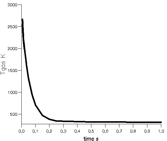
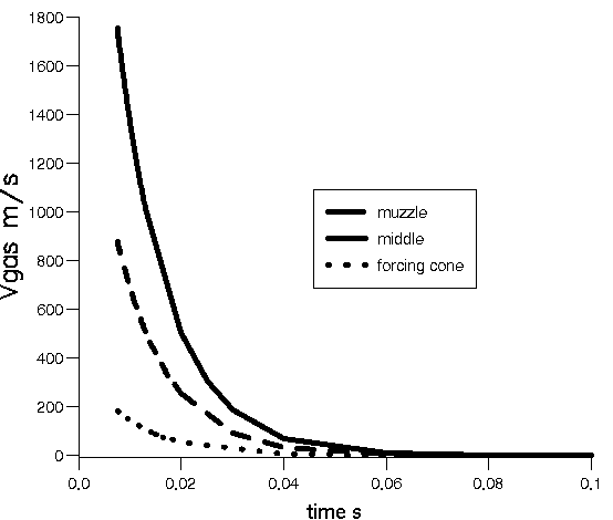
From the 120-mm results of KAMONO code (Pgas, Tgas and Vgas versus time, after the projectile exit), we determine two expansion laws, one for Tgas (exponential decreasing law as a function of the time) and the other for Vgas (exponential decreasing law as a function of the time and the axial abscissa). These laws are used as the inputs of the cooling heat exchange laws and they are easily programmed in THETA code. Figures 2 and 3 show Tgas and Vgas versus the time.
THETA code uses as boundary conditions during the 120-mm shot, the convective flux calculated by MIGAPPAC code [4]. At the end of the first shot cooling, just before the second firing, THETA code has calculated a new initial barrel temperature which enables us to calculate a second shot convective flux and so on, until the end of a burst.
Comparison with experimental results
The comparison was realized for the three sections. Figure 4 shows, for the section located at 1,300 mm from the breech, the results obtained with the MECCAD code and with the sensor measurements. The thermocouples are located at 630 µm and 830 µm from the inner wall.
We can note that the heating calculations are equal to the measurements with a difference lower than 10% (without readjusting calculation). This comparison conclusion is confirmed at the chromium/steel interface location: experimental chromium/steel interface temperature was determined by using an inverse conduction calculation method: see [2].
In this type of approach, there always are uncertainties inherent to the measurement (thermocouple layout and response) combined with a rarely accurate knowledge of thermal characteristics of chromium with the tube age. Moreover, during a shot, experimental temperatures consider the total heat transfers while MECCAD code calculates the heating of the barrel only with the convective heat exchanges, see MIGAPPAC code [4].
During the cooling phase, after 0.1 s, the calculation always over-estimates the temperatures anywhere along the tube: two-dimensional conduction effect. Figure 5 shows that this two-dimensional effect is no longer negligible 50 ms after the shot. Ten seconds after the shot the difference is about 14°C between the one-dimensional and the two-dimensional calculations. However, two-dimensional conduction calculations are quite difficult to realize because we should have a square mesh if we want a good accuracy, which would require a high-powered calculation machine.
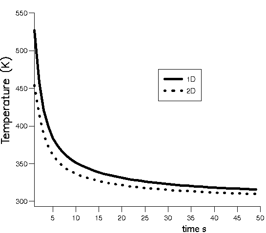
Considering all of this, the comparison compels us to conclude favourably concerning the validation of MECCAD near the forcing cone of the 120-mm calibre gun.
The other sections
The comparison results of the heating phase in the two other sections lead to the same conclusion as the section near the forcing cone. But the difference between calculations (which under-estimate) and experiments increases when we move further away from the forcing cone. We can explain it by the fact that MECCAD code doesn't take into account the heat flux due to the projectile band friction on the inner wall and with the hypothesis that this inner wall heat due to friction (high speed friction) increases with the square root of the projectile velocity.
The sensitivity of the barrel heating and cooling to the temperature profile inside the boundary layer was carried out. First law is Kutateladze and Leontiev’s one [1], the other is Crocco’s law [1]. We observe a difference of 100°C on the inner wall temperature, along the first two thirds of the tube length, between the two laws. We used Kutateladze and Leontiev’s law for the temperature calculation: with this law which gave higher temperatures the calculated barrel temperatures are nearest the measured ones.
The chromium thermal properties at the ambient temperature are characterised by a non-destructive method (the flash method): diffusivity, effusivity and thermal contact between the coating and the substrate [9]. These new values modify a little the chromium temperature during the shot.
Conclusion
The MECCAD code enables us to compute the heating and the cooling of 120-mm chromium-coated gun barrel with APFS-DS during a shot.
The heating phase results, for the section near the forcing cone, are compared successfully with experimental temperature measurements; thermocouples were located in three sections along the barrel and between 250 µm and 900 µm from the inner barrel wall. The difference between calculations and experiments (for the other sections) increases when we remove from the forcing cone. We should take into account the heat flux due to the projectile band friction on the inner wall to reduce this difference. Moreover, in this type of approach, there always are uncertainties inherent to the measurement combined with the fact that there we rarely have an accurate knowledge of thermal characteristics of chromium with the tube age.
Concerning the cooling phase, we should make two-dimensional conduction calculations if we want more accuracy.
The same work was realised with a practice ammunition called "BSCC" (Boulet Simili Charge Creuse).
It is now possible to predict with MECCAD code the heating and the cooling of large calibre guns.
The next steps of our work will concern:
- 120-mm thermo-mechanical calculations with the boundary conditions calculated here, with MECCAD code.
- Comparison between calculation and parietal temperature measurements in a 120-mm chromium-coated gun barrel with APFS-DS with wear-reducing additives.
Acknowledgements
This work is partially sponsored by the French State (DGA/SPART).
This paper was first presented at Gun Tubes 2005, Oxford, England, April 2005.
References
[1] D. Boisson, R. Cayzac, and G. Légeret, “Study of the Gas Discharge and the Heat Exchanges Occurring in a Gun Tube after the Projectile Leaves the Barrel: Validation for the 30mm Gun”, 18th International Symposium on Ballistics, San Antonio, USA, 15–19 Nov 1999.
[2] D. Boisson, G. Légeret, and F. Barthélémy, “Experimental Investigation of Heat Transfer in a 120-mm Testing Gun Barrel Based on an Inverse Heat Conduction Method”, 19th International Symposium on Ballistics, Interlaken, Switzerland, 7–11 May 2001.
[3] D. Boisson, C. Grignon, M. Roux, and P. Gillard, “1D and 2D Thermal Modelling of the Heating and the Cooling of a Gun Barrel During a Burst”, 14th International Symposium on Ballistics, Québec, Canada, 26–29 Sep 1993.
[4] D. Boisson, H. Sadat, F. Rigollet, G. Arnaud, and C. Grignon, “Computation of Boundary Layers and Calculation of Parietal Heat Flux During a Shot in a Gun Barrel”, 15th International Symposium on Ballistics, Jerusalem, Israel, 21–24 May 1995.
[5] H. Guenoche, C. Sedes, and B. Porterie, Internal Ballistic CAPA1D Code, IUSTI Marseille Rpt, 1990.
[6] H.C. Hottel and A.F. Sarofim, Radiative Transfer, McGraw Hill, 1967.
[7] M.N. Ozisik, Heat Transfer—A Basic Approach, McGraw Hill, 1985.
[8] R. Cayzac and E. Carette, “Intermediate Ballistic Computations and Validations”, 17th International Symposium on Ballistics, Midrand, South Africa, 23–27 Mar 1998.
[9] O. Faugeroux, B. Claudet, S. Bénet, J.J. Serra, and D. Boisson. “Caractérisation thermophysique de revêtements par méthode photothermique impulsionnelle en face avant”, International Journal of Thermal Sciences, Vol. 43, pp. 383–401, April 2004.